Mount bracket HONDA CIVIC 2002 7.G Owner's Guide
[x] Cancel search | Manufacturer: HONDA, Model Year: 2002, Model line: CIVIC, Model: HONDA CIVIC 2002 7.GPages: 1139, PDF Size: 28.19 MB
Page 615 of 1139
Conventional Brake Components
Rear Brake Pads Inspection and Replacement
Frequent inhalation of brake pad dust, regardless ofmaterial composition, could be hazardous to your
hea hh.. Avoid breathing dust particles.. Never use an air hose or brush to clean brake
assemblies, Use an OSHA-approved vacuum
cleaner.
Inspection
'1. Raise the rear of the vehicle, and support jt with
safety stands in the proper location (see page 1-8).Remove the rear wheels,
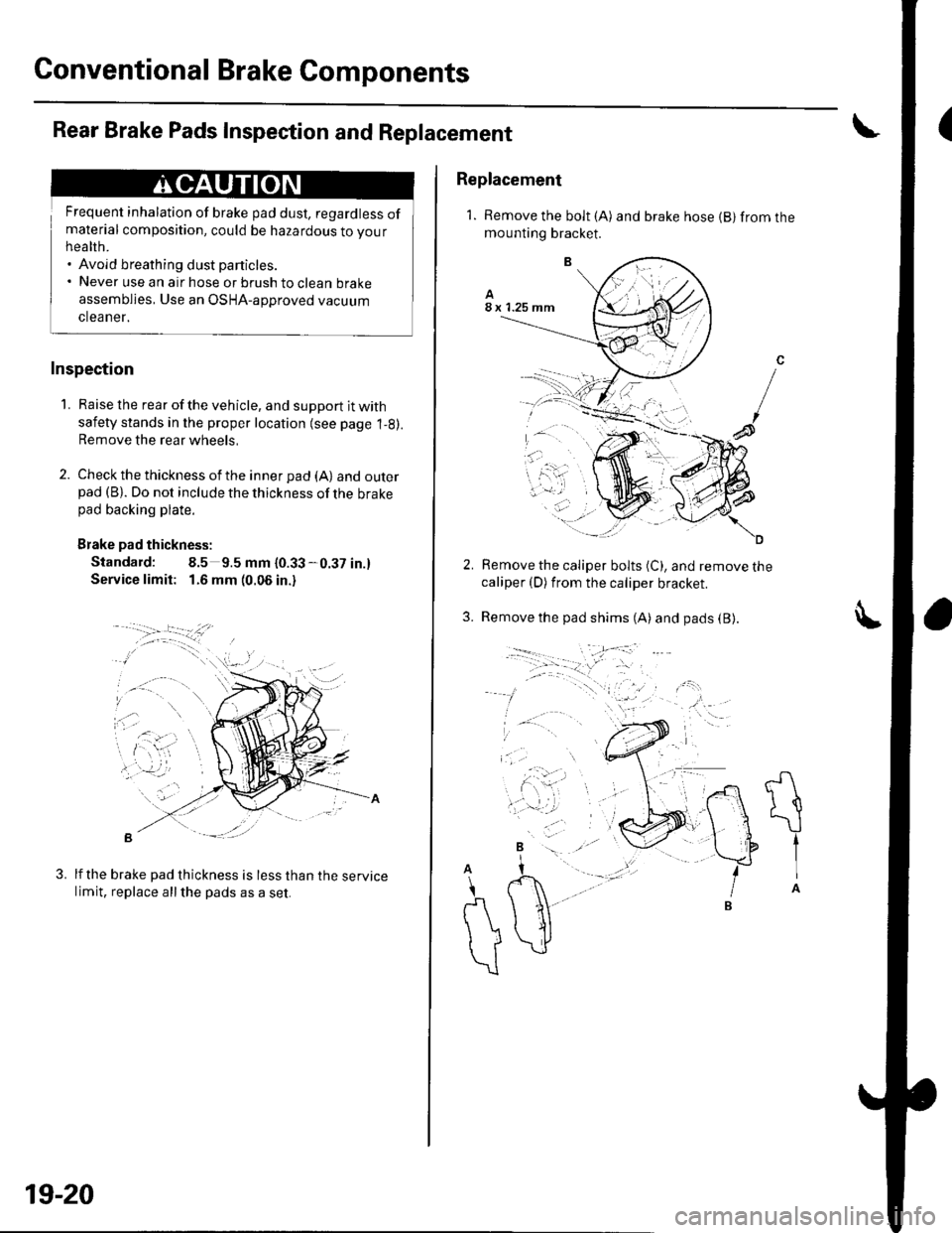
2. Check the thickness of the inner pad (A) andouterpad (B). Do not include the thickness of the brakepad backing plate.
Brake pad thickness:
Standard: 8.5 9.5 mm {0.33-0.37 in.}
Service limit: 1.6 mm (0.06 in.)
B -::--
lf the brake pad thickness is less than the servicelimit, replace allthe pads as a set.
3.
19-20
Replacement
1. Remove the bolt (A) and brake hose {B} from themounting bracket.
Remove the caliper bolts (C), and remove thecaliper (D) from the caliper bracket.
Remove the pad shims (A) and pads (B).3.
A
t{
\
tIA
A
\
r\
))
\
Page 698 of 1139
Moonroof
Drain Channel Slider and Cable Assembly Replacement
1. Remove the frame (see page 20-42).
2. Remove these parts from the frame:
. Sunshade (see page 20-40). Moonroof motor (see page 20-41)
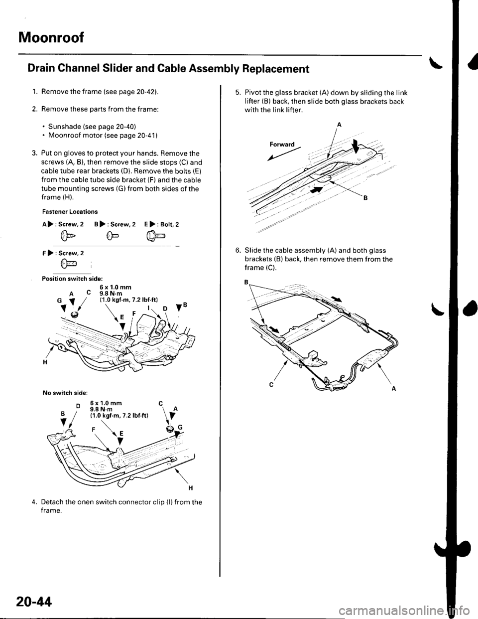
3. Put on gloves to protect your hands, Remove the
screws (A, B), then remove the slide stops (C) and
cable tube rear brackets (D). Remove the bolts (E)
from the cable tube side bracket (F) and the cable
tube mounting screws (G) from both sides of the
frame (H).
Fastener Locations
A> r Screw.2 B): Screw,2
@@
r):
Position switch side:
6x1.0mmA c g,a N.m
No switch sidel
o
E>:Bolt,2
Screw
6\-'1
6x1.0mm C9.8 N.m11.0 kgf.m, 7.2 lbf.ft)
Detach the onen switch connector clip {l)from the
frame.
B
V
20-44
5. Pivotthe glass bracket (A) down by sliding the link
lifter (B) back, then slide both glass brackets back
with the link lifter.
Slide the cable assembly (A) and both glass
brackets (B) back, then remove them from the
frame (C).
Page 700 of 1139
Moonroof
Limit Switch Adjustment
1. Remove the headliner (see page 20-54).
Fully closed position adiustment
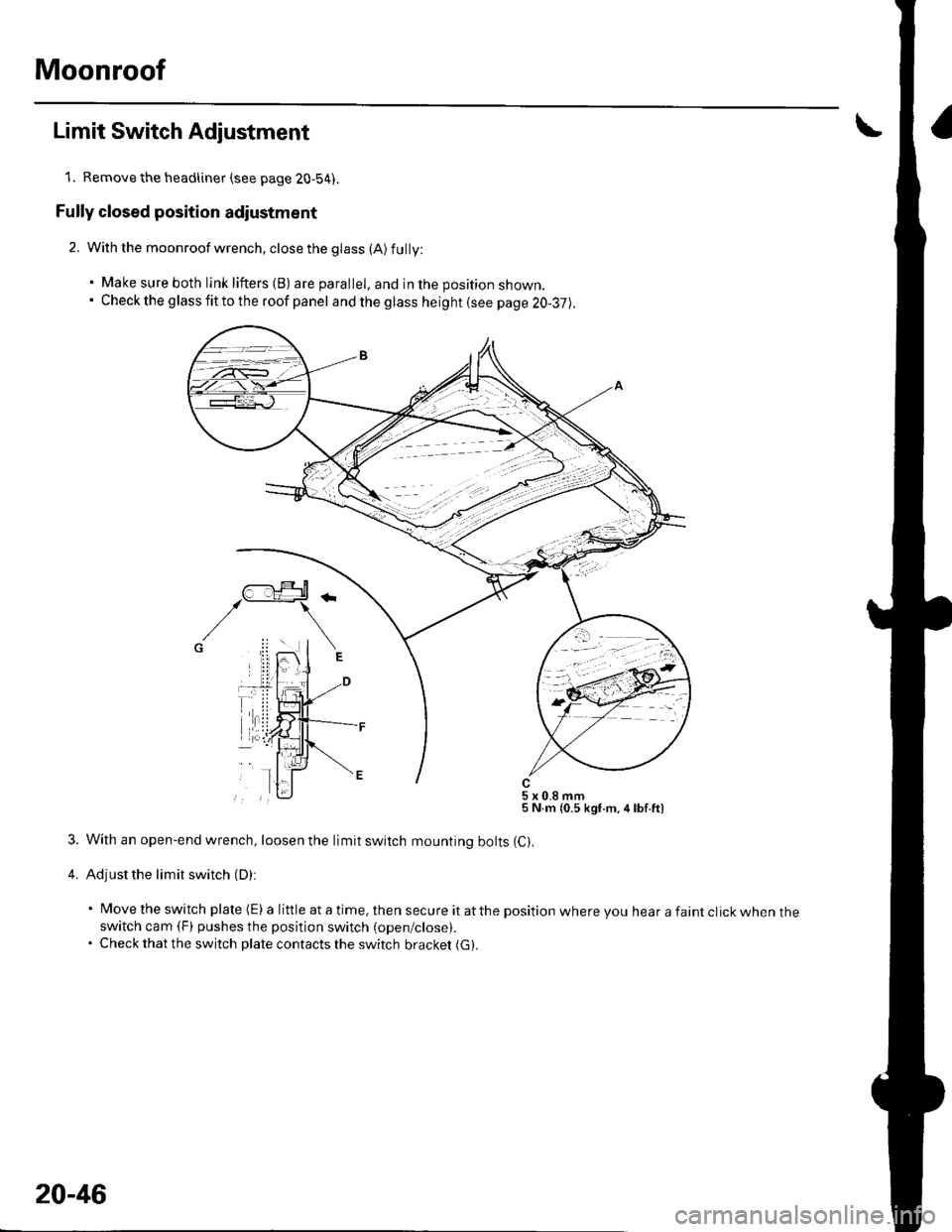
2. With the moonroof wrench, close the glass (A) fully:
. Make sure both link lifters (B) are parallel, and in the position shown.. Check the g lass fit to the roof panel and the glass height (see page 20-37).
5x0.8mm5 N.m {0.5 kgf.m,4lbf.ft)
3. With an open-end wrench, loosen the limit switch mounting bolts (C).
4. Adjust the limit switch (D):
' Move the switch plate (E) a little at a time, then secure it atthe position where you hear a faint click when theswitch cam (F) pushes the position switch (open/close).. Check that the switch plate contacts the switch bracket (G).
20-46
Page 701 of 1139
Auto-stop position adiustment
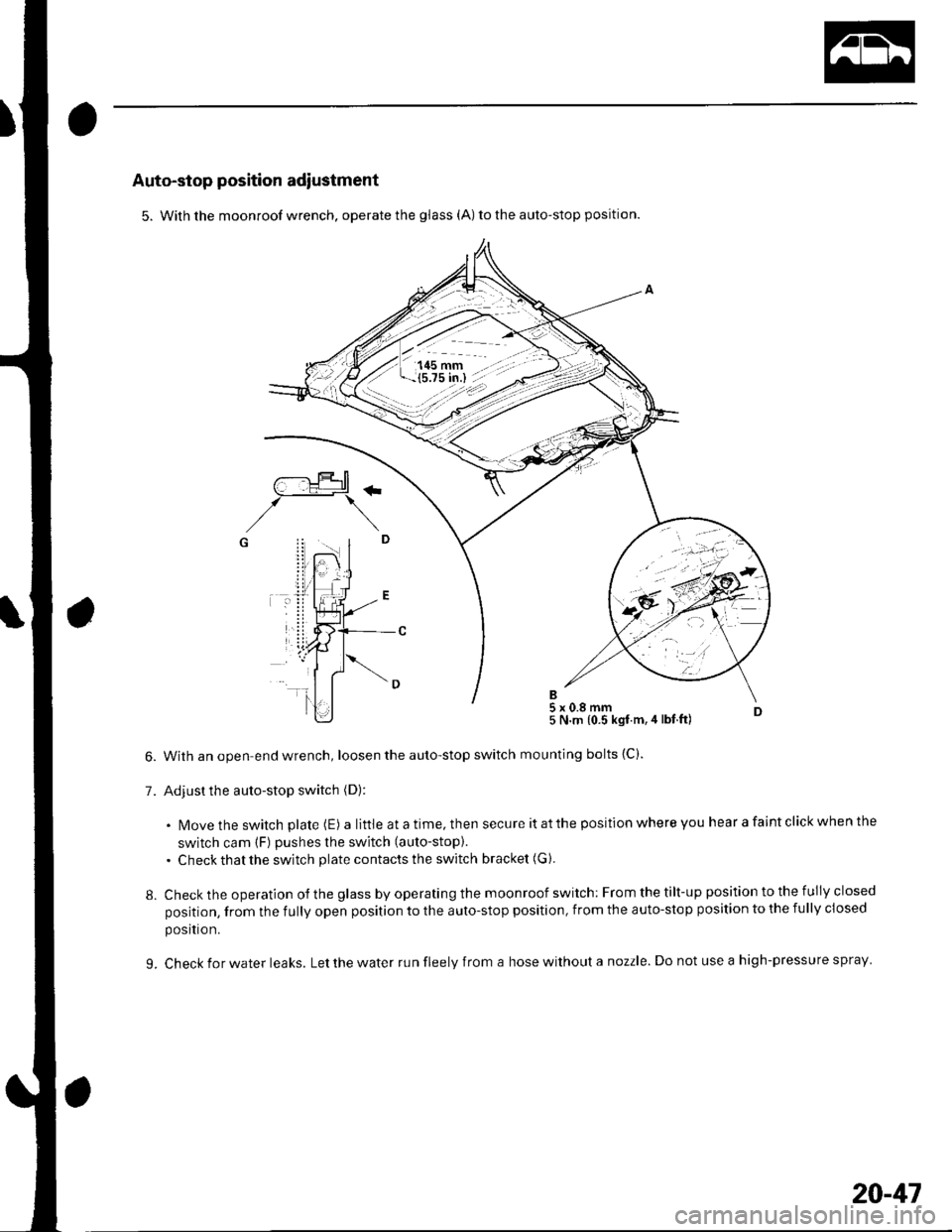
5. With the moonroof wrench. operate the glass (A) to the auto-stop position.
With an open-end wrench, loosen the auto-stop switch
Adjust the auto-stop switch (D):
5 N.m {0.5 kgt.m,4 lbt ft)
mounting bolts (C).
. N4ovethe switch plate (E) alittleatatime,thensecureitatthepositionwhereyouhearafaintclickwhenthe
switch cam (F) pushes the switch (auto-stop).
. Check that the switch plate contacts the switch bracket (G ).
Check the operation of the glass by operating the moonroof switch: From the tilt-up position to the fully closed
position, from the fully open position to the auto-stop position, from the auto-stop position to the fully closed
posltron.
Check for water leaks. Let the water run fleely from a hose without a nozzle. Do not use a high-pressure spray
/--:.!Jtr+rtl\_-_:_t+#1
,/\G i! .. I
7.
8.
L
20-41
Page 806 of 1139
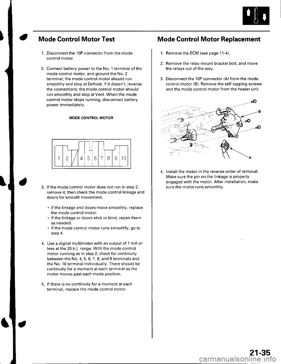
Mode Control Motor Test
Disconnect the 10P connector from the mode
control motor.
Connect battery power to the No. 1 terminal of the
mode control motor, and ground the No. 2
terminal; the mode control motor should run
smoothly and stop at Defrost. lf it doesn't, reverse
the connections; the mode control motor should
run smoothly and stop at Vent. When the mode
control motor stops running, disconnect battery
power immediately.
'1.
4.
MODE CONTROL MOTOR
3. lfthe mode control motor does not run in step 2,
remove it, then check the mode control linkage and
doors for smooth movement.
. lf the linkage and doors move smoothly. replace
the mode control motor.. lf the linkage ordoorsstick or bind, repairthem
as neeoeo.. lfthe mode control motor runs smoothly, go to
step 4.
Use a digital multimeter with an output of 1 mA or
less at the 20 k Q range. With the mode control
motor running as in step 2, check for continuity
between the No. 4,5,6,7,8, and 9 terminals and
the No. 10 terminal individually. There should be
continuity for a moment at each terminal as the
motor moves past each mode position.
lf there is no continuity for a moment at each
terminal. replace the mode control motor.
Mode Control Motor Replacement
2.
3.
1.Remove the ECM (see page 11-4).
Remove the relay mount bracket bolt, and move
the relays out of the way.
Disconnect the 10P connector {A) from the mode
control motor (B). Remove the self-tapping screws
and the mode control motor from the heater unit.
lnstallthe motor in the reverse order of removal.
lvlake sure the pin on the linkage is properly
engaged with the motor. After installation. make
sure the motor runs smoothly.
4.
21-35
Page 807 of 1139
Heating and Air Conditioning
Recirculation Control Motor Test
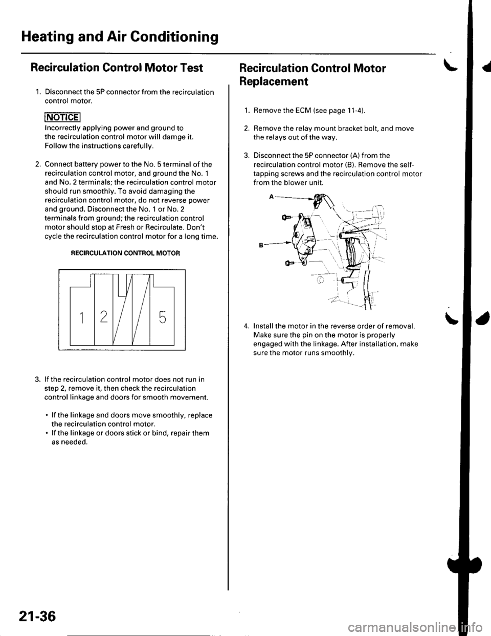
1. Disconnect the 5P connector from the recirculation
control motor.
Incorrectly applying power and ground to
the recirculation control motor will damge it.
Follow the instructions carefullv.
2. Connect batterv oower to the No. 5 terminal ofthe
recirculation control motor, and ground the No. 1
and No. 2 terminals; the recirculation control motor
should run smoothly. To avoid damaging the
recirculation control motor, do not reverse power
and ground. Disconnect the No. 1 or No. 2
terminals from ground; the recirculation control
motor should stop at Fresh or Recirculate. Don't
cycle the recirculation control motor {or a long time.
RECIRCULATION CONTROL MOTOR
lf the recirculation control motor does not run in
step 2, remove it, then check the recirculation
control linkage and doors for smooth movement.
. lfthe linkage and doors move smoothly, replace
the recirculation control motor.. lf the linkageordoorsstickor bind, repairthem
as neeoeo.
21-36
Recirculation Control MotorI
Replacement
1.Remove the ECM (see page 11-4).
Remove the relay mount bracket bolt. and move
the relays out of the way,
Disconnect the 5P connector (A) from the
recirculation control motor (B), Remove the self-
tapping screws and the recirculation control motor
from the blower unit.
Installthe motor in the reverse order of removal.
Make sure the pin on the motor is properly
engaged with the linkage. After installation. make
sure the motor runs smoothly.
\
Page 811 of 1139
Heating and Air Gonditioning
Blower Unit Removal and Installation {cont'd}
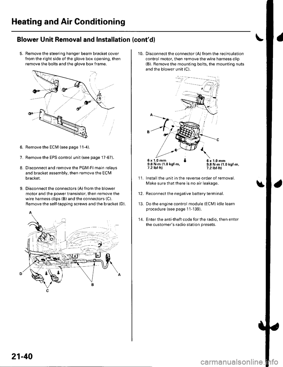
Remove the steering hanger beam bracket cover
from the right side of the glove box opening, then
remove the bolts and the olove box frame.
1.
8.
9.
Remove the ECM (see page 11-4).
Remove the EPS control unit (see page 17-67).
Disconnect and remove the PGM-Fl main relays
and bracket assembly, then remove the ECM
bracket.
Disconnect the connectors {A) from the blower
motor and the power transistor, then remove the
wire harness clips (B) and the connectors (C).
Remove the self-tapping screws and the bracket (D).
A
21-40
10. Disconnectthe connector {A) from the recirculation
control motor, then remove the wire harness clip
{B). Remove the mounting bolts, the mounting nuts
and the blower unit (C).
6x 1.0 mm I9.8 N.m (1.0 kgt.m,7.2 tbt.ftl
6x1.0mm9.8 N.m (1.0 kgf.m,?.2 tbf.ft)
11.
14.
Installlhe unit in the reverse order of removal.
Make sure that there is no air leakage.
Reconnect the negative battery terminal.
Do the engine control module (ECM) idle learn
procedure {see page 11-139).
Enter the anti-theft code for the radio, then enter
the customer's radio station presets.
\
'13.
Page 815 of 1139
Heating and Air Conditioning
Heater Unit/Core Replacement (cont'd)
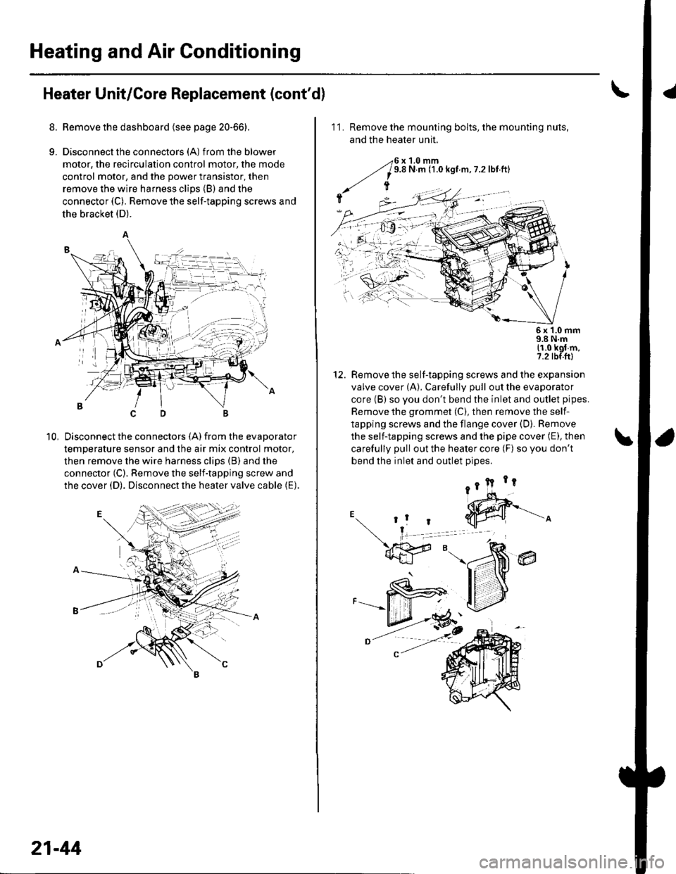
8. Remove the dashboard {see page 20-66).
9. Disconnectthe connectors (A) from the blower
motor, the recirculation control motor, the mode
control motor, and the power transistor, then
remove the wire harness clips (B) and the
connector (C). Remove the self-tapping screws and
the bracket (D).
Disconnect the connectors (A) from the evaporator
temperature sensor and the air mix control motor,
then remove the wire harness clips (B) and the
connector (C). Remove the self-tapping screw and
the cover (D). Disconnect the heater valve cable (E).
10,
7t,
21-44
11. Remove the mounting bolts, the mounting nuts,
and the heater unit.
Remove the self-tapping screws and the expansion
valve cover (A). Carefully pull out the evaporator
core (B) so you don't bend the inlet and outlet pipes.
Remove the grommet (C), then remove the self-
tapping screws and the flange cover (D). Bemove
the self-tapping screws and the pipe cover (E), then
carefully pull out the heater core (F) so you don't
bend the inlet and outlet oioes.
@
5x 1.0 mm9.8 N.m11.0 kgl m,7.2 tbf.ftl
12.
Page 834 of 1139
General Troubleshooting Information
Tips and Precautions
Bef ore Troubleshooting
1. Check applicable fuses in the appropriate fuse/relay
oox.
2. Check the battery for damage. state of charge, and
clean and tight connections.
. Do not quick-charge a battery unless the battery
ground cable has been disconnected, otherwise
you will damage the alternator diodes.. Do not attempt to crank the engine with the
battery ground cable loosely connected or you
will severely damage the wiring.
Handling Connectors. Make sure the connectors are clean and have no
loose wire terminals.. Make sure multiple cavity connectors are packed with
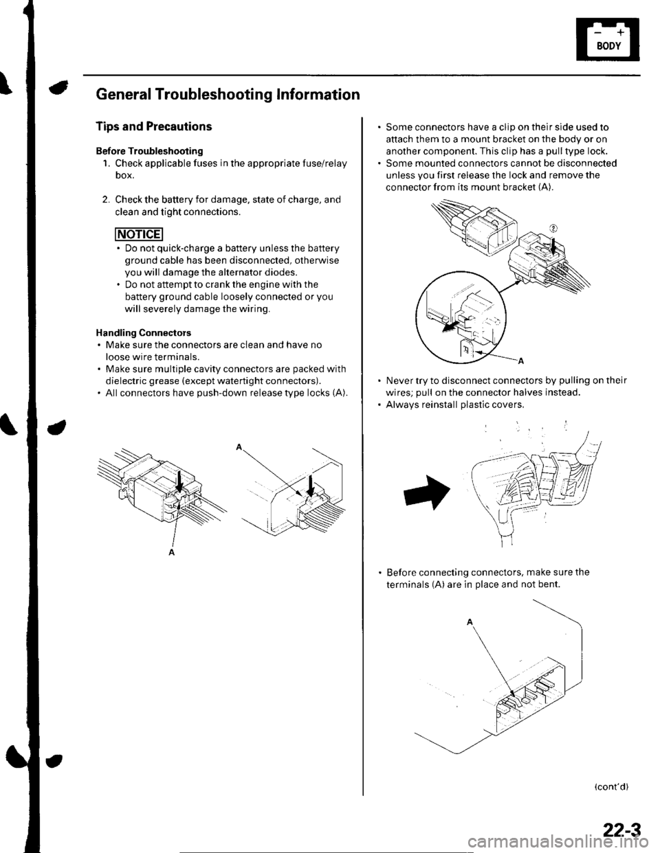
dielectric grease (except waterti ght connectors).. All connectors have push-down release type locks (A).
Some connectors have a clip on their side used to
attach them to a mount bracket on the body or on
another component. This clip has a pull type lock.
Some mounted connectors cannot be disconnected
unless you first release the lock and remove the
connector from its mount bracket (A).
Never try to disconnect connectors by pulling on their
wires; pull on the connector halves instead.
Alwavs reinstall Dlastic covers,
Before connecting connectors, make sure the
terminals (A) are in place and not bent.
(cont'd)
22-3
Page 880 of 1139
Under-dash Fuse/Relay Box
Removal and Installation
SRS components are located in this area. Review the
SRS component locations {see page 23-13) andprecautions and procedures (see page 23-14) in the SRS
section before performing repairs or service.
Removal
1. Make sure you have the anti-theft code for the radio,
then write down the frequencies for the radio's
preset buttons.
2. Disconnectthe battery negative cable, then
disconnect the positive cable, and wait at least
three minutes.
3. Remove the driver's dashboard lower cover (see
page 20-59).
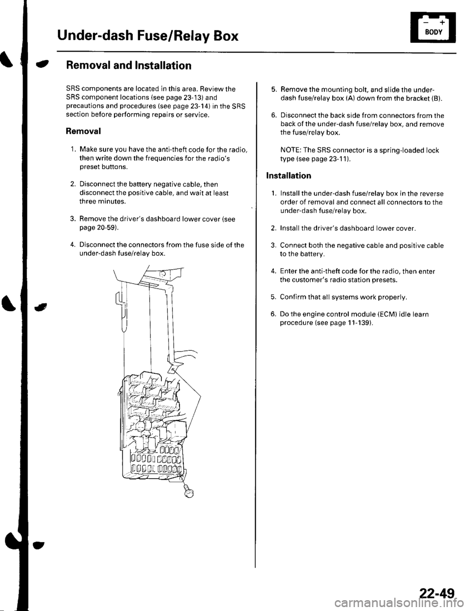
4. Disconnect the connectors from the fuse side of the
under-dash fuse/relay box.
5. Remove the mounting bolt, and slide the under-
dash fuse/relay box (A) down from the bracket {B).
6. Disconnect the back side from connectors from the
back of the under-dash fuse/relay box, and remove
the fuse/relay box.
NOTE:The SRS connector is a spring-loaded lock
type (see page 23-1 1).
lnstallation
1. Installthe under-dash fuse/relay box in the reverse
order of removal and connect all connectors to the
under-dash fuse/relay box.
2. Installthe driver's dashboard lower cover.
3. Connect both the negative cable and positive cable
to the battery.
4. Enter the anti-theft code for the radio, then enter
the customer's radio station presets.
5. Confirm that all systems work properly,
6. Do the engine control module (ECM) idle learn
procedure (see page 11-139).
22-49