Mount bracket HONDA CIVIC 2002 7.G Owner's Manual
[x] Cancel search | Manufacturer: HONDA, Model Year: 2002, Model line: CIVIC, Model: HONDA CIVIC 2002 7.GPages: 1139, PDF Size: 28.19 MB
Page 421 of 1139
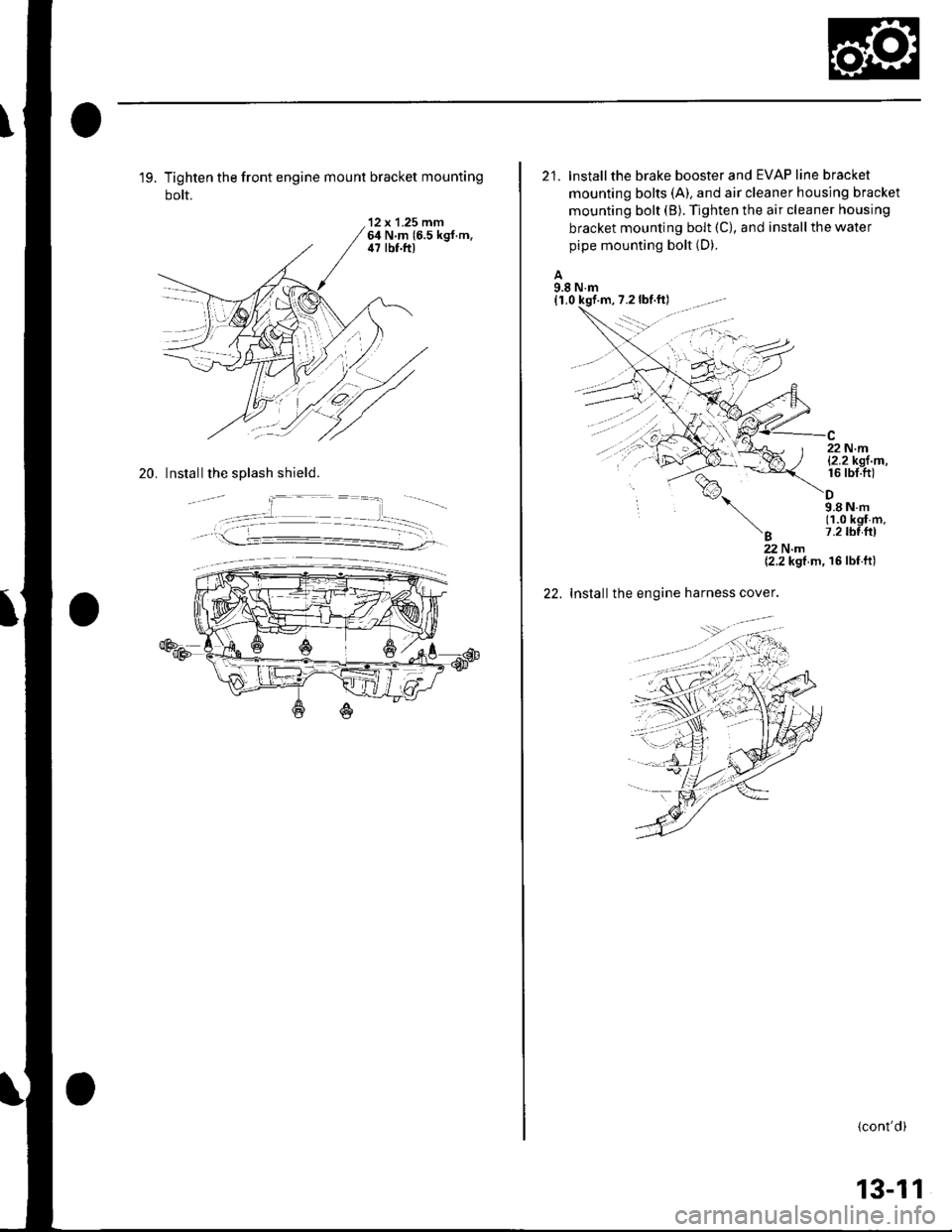
19. Tighten the front engine mount bracket mounting
bolt.
'12 x 1.25 mm64 N.m 16.5 kgf.m,il7 lbf.ft)
20. Install the splash shield.
21. lnstallthe brake booster and EVAP line bracket
mounting bolts (A). and air cleaner housing bracket
mounting bolt (B). Tighten the air cleaner housing
bracket mounting bolt (C), and install the water
pipe mounting bolt (D).
A9.8 N.m(1,0 kqf
%,
'B
22 N.ml2.2kgl m,16 rbt.ft)
9.8Nm(1.0 kgf m.7.2 tbl{rl
22.
22Nm{2.2 kgf m, 16 lbf ft)
Installthe engine harness cover.
(cont'd)
13-11
Page 505 of 1139
Rack Guide Adjustment
Special Tool Required
Locknut wrench, 43 mm 07MAA-S100200
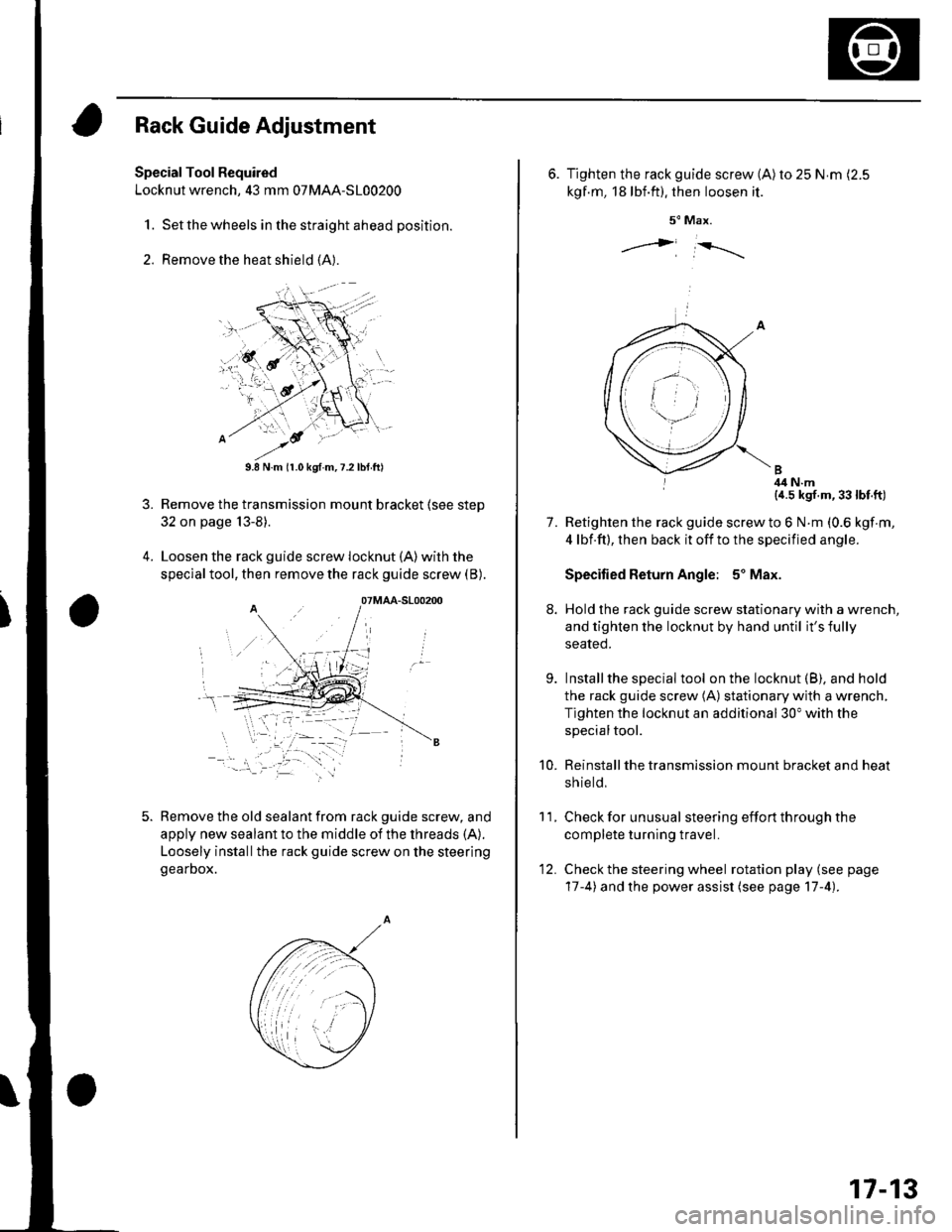
1. Set the wheels in the straight ahead position.
2. Remove the heat shield (A).
3.
9.8 N.m (r.0 kgf.m,7.2lbtft)
Remove the transmission mount bracket (see step
32 on page 13-8).
Loosen the rack guide screw locknut (A)with the
special tool, then remove the rack guide screw (B).
Remove the old sealant from rack guide screw, and
apply new sealant to the middle of the threads (A).
Loosely installthe rack guide screw on the steering
gearDox.
'-.i. '' '
07MAA-S100200
6. Tighten the rack guide screw (A)ro 25 N.m (2.5
kgf.m, 18lbf.ft). then loosen it.
5" Max.
j i-rrrr-,
I 4il N.m{a.5 kgf.m,33lbt.ft)
Retighten the rack guide screw to 6 N.m (0.6 kgf m,
4 lbf.ft), then back it off to the specified angle.
Specified Return Angle: 5' Max.
Hold the rack guide screw stationary with a wrench,
and tighten the locknut by hand until it's fully
seated.
Installthe special tool on the locknut (B), and hold
the rack guide screw (A) stationary with a wrench,
Tighten the locknut an additional 30" with the
specialtool.
Reinstall the transmission mount bracket and heat
sh ie ld,
Check for unusual steering effort through the
complete turning travel.
Check the steering wheel rotation play (see page
17-4) and the power assist (see page 17-4).
11.
7.
9.
10.
12.
17-13
Page 543 of 1139
EPS Components
Steering Gearbox Removal (cont'd)
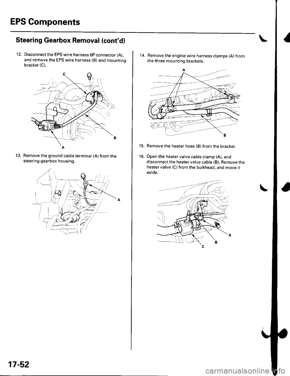
Disconnect the EPS wire harness 6P connector (A),
and remove the EPS wire harness (B) and mountino
bracket (C).
12.
Remove the ground cable terminal (A) from the
steering gearbox housing.
..(
.,/ a
b-H\
ry T,-.lt'^ \
'" \--
13.
_-1..1.-'
-a--zii F--_1
17-52
14. Remove the engine wire harness clamps {A)fromthe three mounting brackets.
Remove the heater hose {B) from the bracket.
Open the heater valve cable clamp (A), and
disconnect the heater valve cable (B). Remove theheater valve (C) from the bulkhead, and move jt
aside.
t5.
16.
I
Page 554 of 1139
Steering Gearbox Installation
2.
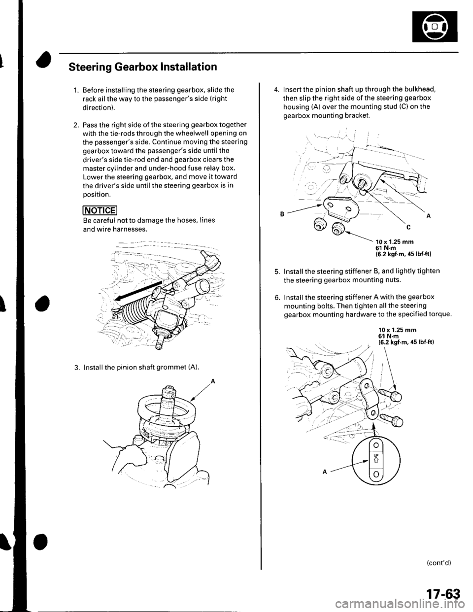
'1.Before installing the steering gearbox, slide the
rack all the way to the passenger's side (right
direction).
Pass the right side of the steering gearbox together
with the tie-rods through the wheelwell opening on
the passenger's side. Continue moving the steering
gearbox toward the passenger's side untilthe
driver's side tie-rod end and gearbox clears the
master cylinder and under-hood fuse Ielay box.
Lower the steering gearbox. and move it toward
the driver's side untilthe steering gearbox is ln
Dosition.
Be careful not to damage the hoses, lines
and wire harnesses.
3. Installthe pinion shaft grommet (A).
4. Insert the pinion shaft up through the bulkhead,
then slip the right side of the steering gearbox
housing (A) over the mounting stud (C) on the
gearbox mounting bracket.
\- --' '.'', i
10 x '1.25 mm61 N.m{6 2 kgl m, 45 lb{ ftl
Install the steering stiffener B, and lightly tighten
the steering gearbox mounting nuts.
Install the steering stiffener A with the gearbox
mounting bolts. Then tighten allthe steering
gearbox mounting hardware to the specified torque.
10 x 1.25 mm6l N.m(6.2 kgt.m, 45 lbt.ft)
: --.-{..
(cont'd )
:-1....
17-63
Page 555 of 1139
EPS Components
Steering Gearbox Installation (cont'd)
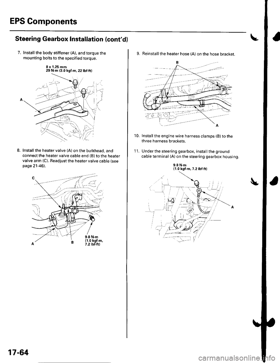
7. Installthe body stiffener (A), and torque the
mounting bolts to the specified torque.
8 x 1.25 mm29 N.m {3.0 kgf.m,22lbf.ftl
LInstall the heater valve (A) on the bulkhead, and
connect the heater valve cable end (B) to the heater
valve arm (C). Readjust the heater valve cable {seepage 21-46).
9.8 N.m(1.0 kgf m,7.2 tbf.ftl
L-t ,:.i.t'
17-64
9. Reinstall the heater hose (A) on the hose bracket.
Install the engine wire harness clamps (B) to the
three harness brackets.
Under the steering gearbox, install the ground
cable terminal (A) on the steering gearbox housing.
10.
'I t.
9.8 N.m{1.0 kgf.m, 7.2lbf.ft)
Page 570 of 1139
Front Suspension
Knuckle/Hub/Wheel Bearing Replacement {cont'dl
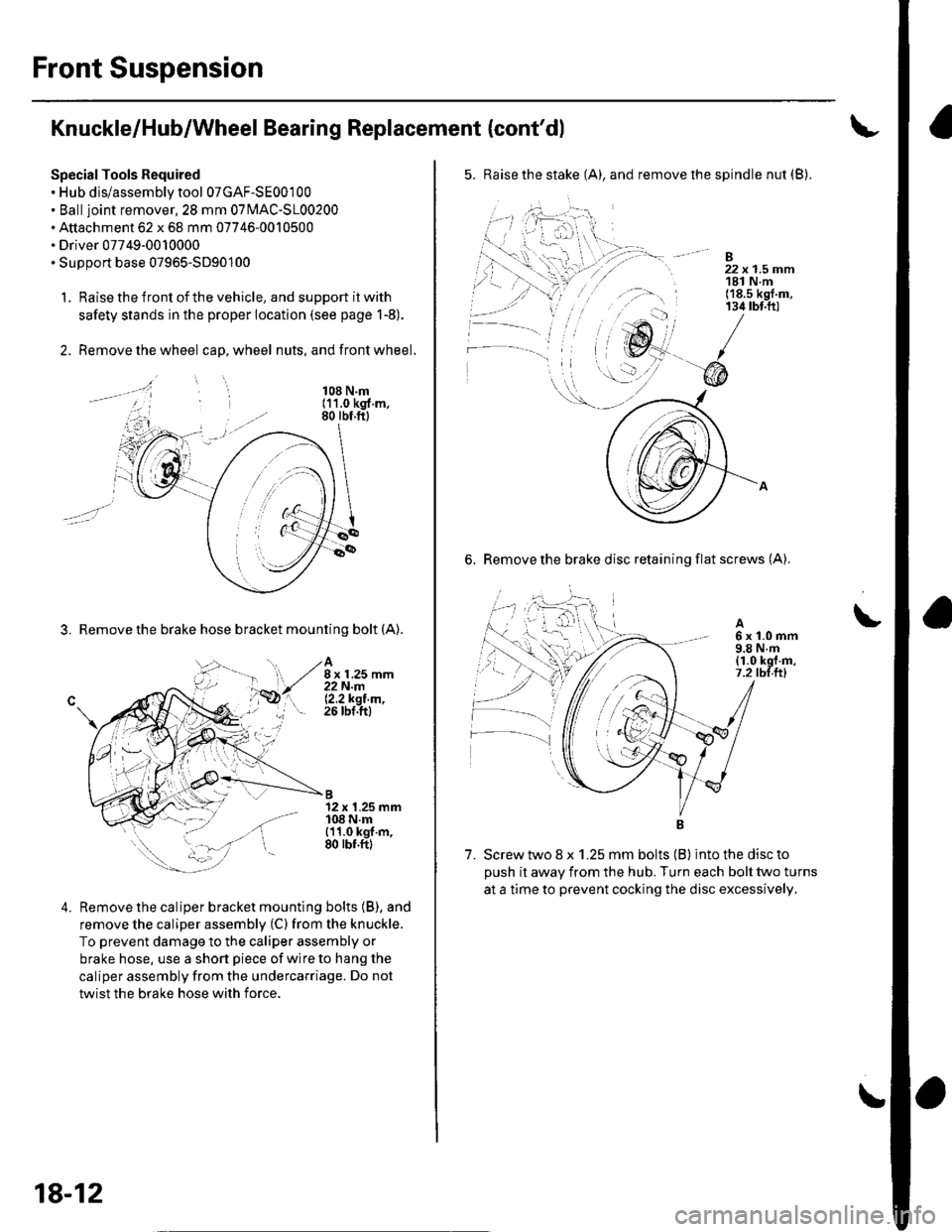
Special Tools Required. Hub dis/assembly tool 07GAF-SE00100. Balljoint remover,2S mm 0TlvlAC-S100200. Attachment 62 x 68 mm 07746-0010500. Driver 07749-0010000. SuDDort base 07965-5D90'100
1. Raise the front of the vehicle, and support it with
safety stands in the proper location (see page 1-8).
2. Remove the wheel cap, wheel nuts, and front wheel.
3. Remove the brake hose bracket mounting bolt (A).
108 N.m(11.0 kgf m,80 rbf.ftl
A8 x 1.25 mm22N.m12.2ksl.m,26 tbf.ftl
B12 x 1.25 mm108 N.m{11.0 kgf.m,80 rbf.ftl
4.Remove the caliper bracket mounting bolts (B), and
remove the caliper assembly (C) from the knuckle.
To prevent damage to the caliper assembly or
brake hose, use a short piece of wire to hang the
caliper assembly from the undercarriage. Do not
twist the brake hose with force.
18-12
5. Raise the stake (A), and remove the spindle nut (B).
-B
' 22x1.5mm, 181 N.m('18.s kgf.m,134 tbt.ft)
6. Remove the brake disc retaining flat screws (A).
A6x1.0mm9.8 N.m{1.0 kgt.m,7.2 tbl.ttl
7. Screw two 8 x 1.25 mm bolts (B) into the disc to
oush it awav from the hub. Turn each bolt two turns
at a time to prevent cocking the disc excessively,
\
\
Page 585 of 1139
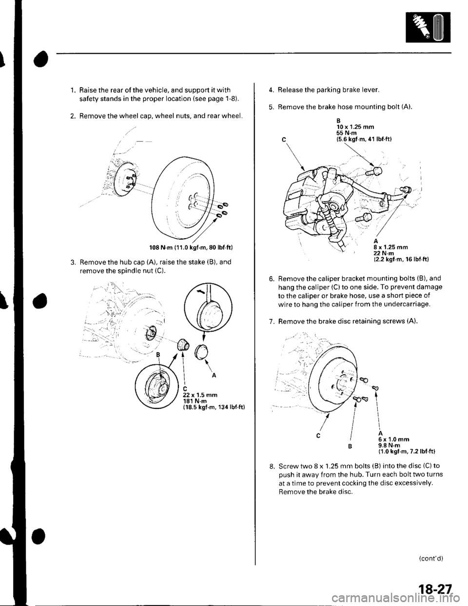
1.Raise the rear of the vehicle, and support it with
safety stands in the proper location (see page 'l-8).
Remove the wheel cap. wheel nuts, and rear wheel.
108 N.m (11.0 kgf.m,80 lbf ftl
Remove the hub cap (A), raise the stake (B), and
remove the spindle nut (C).
O
\A
22 x 1,5 mm181 N.m(18.5 kgf.m, 134lbf.ftl
5.
7.
Release the parking brake lever.
Remove the brake hose mounting bolt (A).
B10 x 1.25 mm55NmC {5.6 kgf m.41 lbf.ft}
(2.2 kgt m, 16lbt.ftl
Remove the caliper bracket mounting bolts (B), and
hang the caliper (C) to one side. To prevent damage
to the caliper or brake hose, use a short piece of
wire to hang the caliper from the undercarriage.
Remove the brake disc retaining screws (A).
Screw two 8 x 1.25 mm bolts (B) into the disc {C) to
oush it awav from the hub. Turn each bolt two turns
at a time to prevent cocking the disc excessively.
Remove the brake disc.
(cont'd)
ap
t
\
IA6x1.0mm9.8 N.m(1.0 kgf.m, ?.2lbf.ftl
18-27
Page 586 of 1139
Rear Suspension
Hub Bearing Unit Replacement
(cont'd)
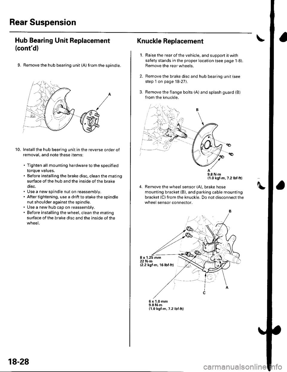
9. Remove the hub bearing unit (A) from the spindle.
Install the hub bearing unit in the reverse order of
removal, and note these items:
. Tighten all mounting hardware to the specified
torque values,. Before installing the brake disc, clean the mating
surface ot the hub and the inside of the brake
disc.. Use a new spindle nut on reassembly.. After tightening, use a drift to stake the spindle
nut shoulder against the spindle.. Use a new hub cap on reassembly.. Before installing the wheel, clean the mating
surface of the brake disc and the inside of the
wneel.
10.
,=,,,
18-28
Raise the rear of the vehicle, and suppon it with
safety stands in the proper location (see page 1-8).
Remove the rear wheels.
Remove the brake disc and hub bearing unit (see
step 1 on page 18-27).
Remove the flange bolts (A) and splash guard (B)
from the knuckle.
11.0 kgf.m, 7.2 lbf ft)
4. Remove the wheel sensor(A), braKe nose
mounting bracket (B), and parking cable mounting
bracket (C) from the knuckle. Do not disconnect the
wheel sensor connector.
8 x 1.25 mm22 N.m{2.2 kgf m, 16 lbf ftl
Knuckle Replacement
1.
6x1.0mm9.8 N,m{I.0 kgt.m,7.2 lbf ft)
tt
Page 590 of 1139
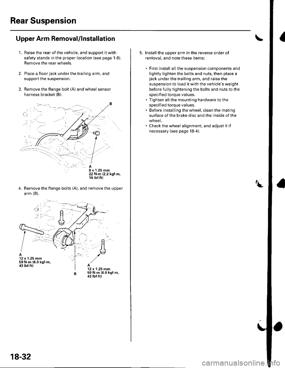
Rear Suspension
Upper Arm Removal/lnstallation
1.Raise the rear of the vehicle, and support lt with
safety stands in the proper location (see page 1-8).
Remove the rear wheels.
Place a floor jack under the trailing arm, and
support the suspensron.
Remove the flange bolt (A) and wheel sensor
harness bracket (B).
8 x 1.25 mm22 N.m (2.2 kgf.m,16 rbf.ft)
Remove the flange bolts (A), and remove the upper
arm {B).
12 x 1.25 mm59 N.m {6.0 kgf.m,ir3 lbf.ft)12 x 1.25 mm59 N.m 16.0 kgf m,43 tbf.ft)
18-32
5. Installthe upper arm in the reverse order of
renloval, and note these items:
. First install allthe suspension components and
lightly tighten the bolts and nuts, then place ajack under the trailing arm, and raise the
suspension to load it with the vehicle's weight
before fully tightening the bolts and nuts to the
specified torque values.. Tighten allthe mounting hardware to the
specified torque values.' Before installing the wheel, clean the mating
surface of the brake disc and the inside of the
wheel.. Check the wheel alignment, and adjust it if
necessary (see page 18-4).
Page 614 of 1139
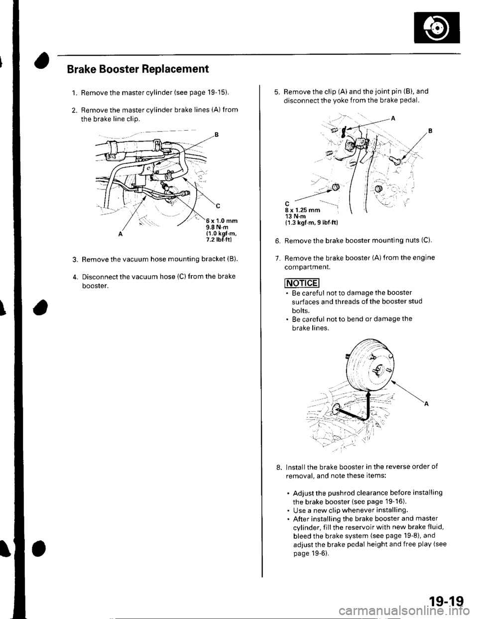
Brake Booster Replacement
1.Remove the master cylinder (see page 19-15).
Remove the master cylinder brake lines {A) from
the brake line clip.
c
6x1.0mm9.8 N.m(1.0 kgf.m,7.2 tbf.ft)
Remove the vacuum hose mounting bracket (B).
Disconnect the vacuum hose {C) from the brake
booster.
'-/
.,.,....
alu
i '..
5. Remove the clip (A) and the joint pin (B). and
disconnectthe yoke from the brake pedal.
7.
{'l.3 kgf.m,9 lbf.ftl
Remove the brake booster mounting nuts (C).
Remove the brake booster (A)from the engine
comparlmenr.
INdAdEI. Be careful not to damage the booster
surfaces and threads of the booster stud
bolts.. Be careful not to bend or damage the
brake lines.
lnstallthe brake booster in the reverse order of
removal, and note these items:
. Adjust the pushrod clearance before installing
the brake booster (see page 19-16).. Use a new clip whenever installing.. After installing the brake booster and master
cylinder, fill the reservoir with new brake fluid,
bleed the brake system (see page 19-8), and
adjust the brake pedal height and free play (see
page 19-6),
19-19