fuse box HONDA CIVIC 2002 7.G Service Manual
[x] Cancel search | Manufacturer: HONDA, Model Year: 2002, Model line: CIVIC, Model: HONDA CIVIC 2002 7.GPages: 1139, PDF Size: 28.19 MB
Page 545 of 1139
EPS Components
Steering Gearbox Removal {cont'd)
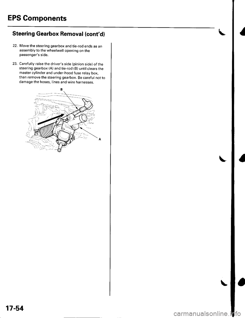
22. Move the steering gearbox and tie-rod ends as anassembly to the wheelwell opening on thepassenger's side.
23. Carefully raise the driver's side (pinion side) ofthesteering gearbox (A) and tie-rod (B) until clears themaster cylinder and under-hood fuse relay box,
then remove the steering gearbox. Be careful not to
damage the hoses, lines and wtre narnesses.
17-51
Page 554 of 1139
Steering Gearbox Installation
2.
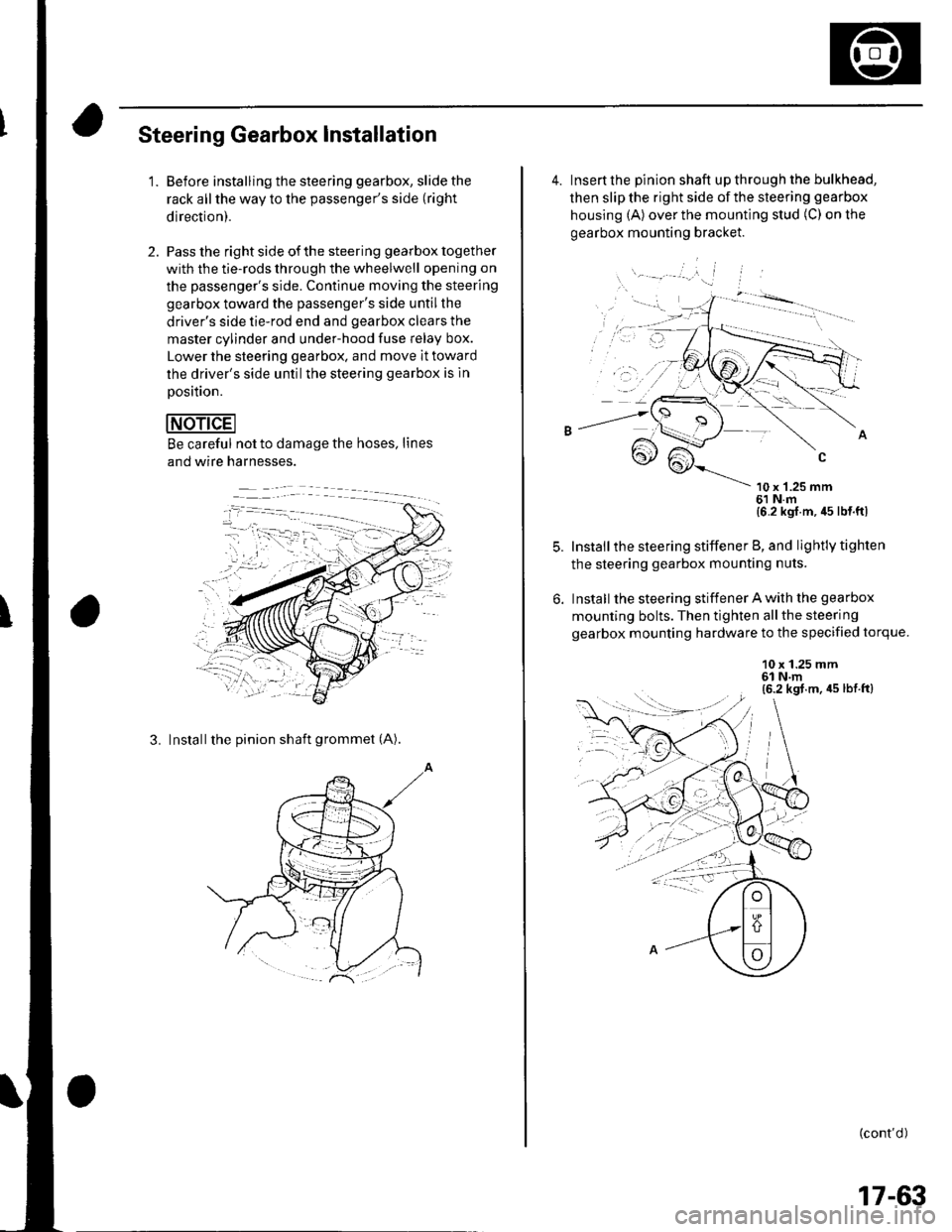
'1.Before installing the steering gearbox, slide the
rack all the way to the passenger's side (right
direction).
Pass the right side of the steering gearbox together
with the tie-rods through the wheelwell opening on
the passenger's side. Continue moving the steering
gearbox toward the passenger's side untilthe
driver's side tie-rod end and gearbox clears the
master cylinder and under-hood fuse Ielay box.
Lower the steering gearbox. and move it toward
the driver's side untilthe steering gearbox is ln
Dosition.
Be careful not to damage the hoses, lines
and wire harnesses.
3. Installthe pinion shaft grommet (A).
4. Insert the pinion shaft up through the bulkhead,
then slip the right side of the steering gearbox
housing (A) over the mounting stud (C) on the
gearbox mounting bracket.
\- --' '.'', i
10 x '1.25 mm61 N.m{6 2 kgl m, 45 lb{ ftl
Install the steering stiffener B, and lightly tighten
the steering gearbox mounting nuts.
Install the steering stiffener A with the gearbox
mounting bolts. Then tighten allthe steering
gearbox mounting hardware to the specified torque.
10 x 1.25 mm6l N.m(6.2 kgt.m, 45 lbt.ft)
: --.-{..
(cont'd )
:-1....
17-63
Page 604 of 1139
GRN/ORN
,tk ,o"","o ""o*.(b, 3s1E8,.""",,"
I oPEN,Leve,down
I-=:
I
A
YBtK
+csor
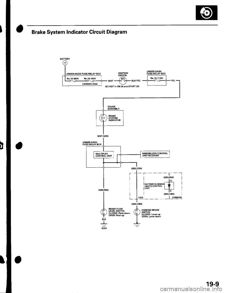
Brake System Indicator Circuit Diagram
UNDER.OASHFUSE/FELAYBOX
EBAK€FLUIDIEVELSwlICH
19-9
Page 624 of 1139
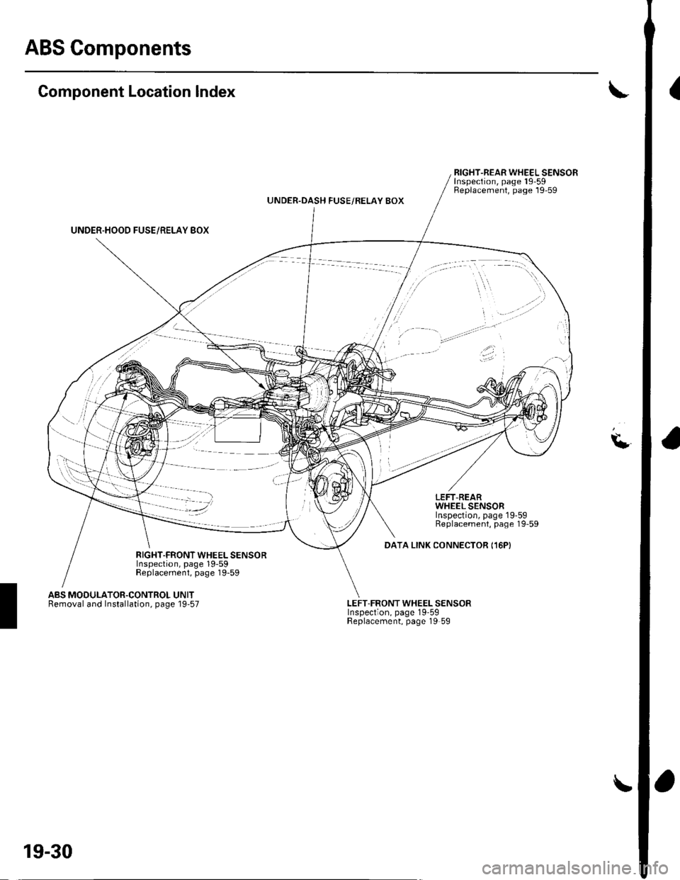
ABS Gomponents
(Component Location Index
UNDER.HOOD FUSE/RELAY BOX
RIGHT-REAR WHEEL SENSORInspection, page 19-59Replacement, page 19-59UNDER.OASH FUSE/RELAY BOX
\L
LEFT.REARWHEEL SENSORInspection, page 19-59Replacement, page 19-59
DATA LINK CONNECTOR I16PIRIGHT.FRONT WHEEL SENSORInspection, page 19-59Replacement, page 19-59
ABS MODULATOR.CONTROL UNITRemoval and Installation, page 19'57LEFT-FRONT WHEEL SENSORInspection, page 19-59Replacement, page 19 59
19-30
Page 638 of 1139
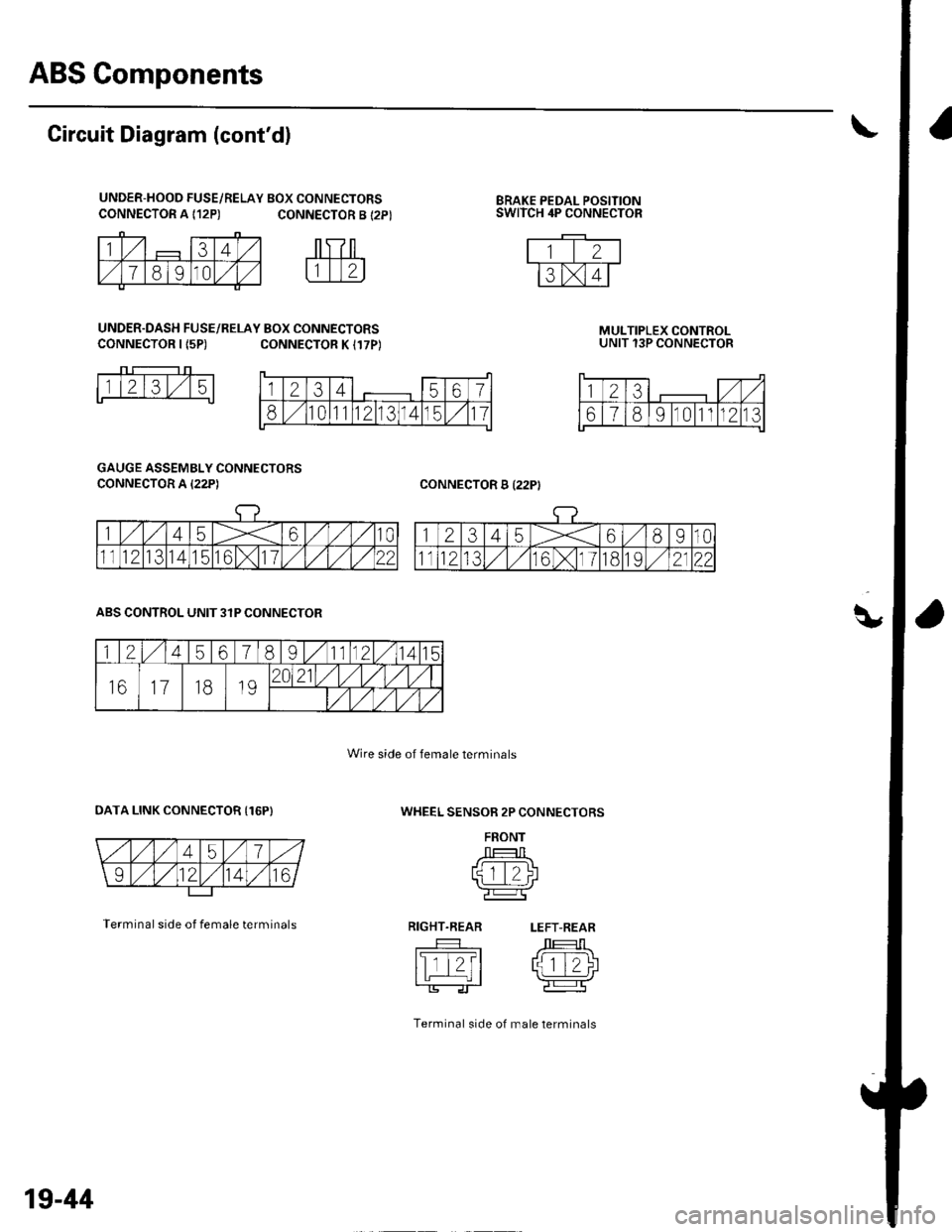
ABS Components
q,
CONNECTOR A {12P)BRAKE PEDAL POSITIONSWITCH 4P CONNECTOR
Circuit Diagram (cont'd)
UNDER-HOOD FUSE/RELAY BOX CONNECTORSCONNECTOR A {12P) CONNECTOR B {2P}
UNDER.DASH FUSE/RELAY BOX CONNECTORSCONNECTOR I {5P)CONNECTOR K I17P)MULTIPLEX CONTROLUNIT 13P CONNECTOR
CONNECTOR B I22PI
1l2l3l,/15
GAUGE ASSEMBLY CONNECTORS
CONNECTOR A I22P)
WHEEL SENSOR 2P CONNECTORS
FRONT
J --T:-l Ltqtt/)l'l L_.:-:J r\-r-----Tr'e:l
RIGHT.REAR LEFT-REAR
tslTt?t /J 1T-1\I tL | rlziJ
Terminal side of male lerminals
ABS CONTROL UNIT 3IP CONNECTOR
OATA LINK CONNECTOR {16P)
Terminal side of female terminals
Wire side of female terminals
1234567
810111213141511
123,/ ,/
67891011n213
1245678I11121415
161118192021/1,/1,/vl,/l
/t,/t/t,/t/
19-44
Page 643 of 1139
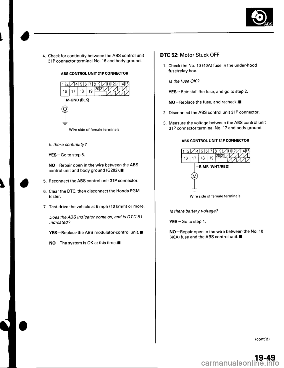
4. Check for continuity between the ABS control unit
31 P connector terminal No. 16 and body grou nd.
ABS CONTROL UNIT 31P CONNECTOR
Wire side of female terminals
ls there continuity?
YES-Go to step 5.
NO Repair open in the wire between the ABS
control unit and body ground (G202).1
Reconnect the ABS control unit 31P connector.
Clear the DTC, then disconnect the Honda PGM
tester.
Test-drive the vehicle at 6 mph (10 km/h) or more.
Doesthe ABS indicator come on, and is DTC 51
indicated?
YES Replace the ABS modulator-control unit.l
NO The system is OK at this time.l
6.
7.
DTG 52: Motor Stuck OFF
1. Check the No. 10(40A) fuse in the under-hood
fuse/relay box.
ls the f use OK?
YES-Reinstall the fuse, and go to step 2.
NO-Replace the fuse, and recheck.l|
Disconnect the ABS control unit 31P connector.
Measure the voltage between the ABS control unit
31P connector terminal No. 17 and body ground
ABS CONTROL UNIT 31P CONNECTOR
2.
3.
ls there battery voltage?
YES-Go to step 4.
NO Repair open in the wire between the
(40A) fuse and the ABS control unit.l
No. 10
(cont'di
Wire side of female terminals
19-49
Page 645 of 1139
DTC 54: Main Relay Stuck OFF
1. Checkthe No.8 (20A) fuse in the under-hood fuse/
relay box, and reinstallthe fuse if it is OK.
ls the f use OK?
YES-Go to step 2.
NO Replace the fuse, and recheck.l
2. Disconnect the ABS control unit 31P connector.
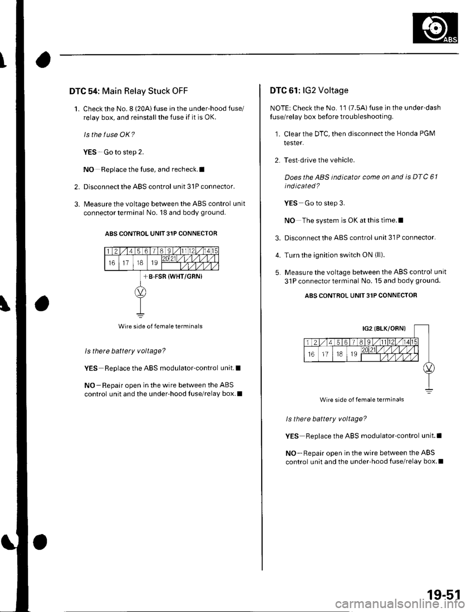
3. l\4easure the voltage between the ABS control unit
connector terminal No. 18 and body ground.
ABS CONTROL UNIT 31P CONNECIOR
Wire side of female terminals
Is there battety voltage?
YES Replace the ABS modulator-control unit.l
NO-Repair open in the wire between the ABS
control unit and the under-hood fuse/relay box.I
DTC 61: lG2 Voltage
NOTE: Check the No. 11 (7.5A) fuse in the under-dash
fuse/relay box before troubleshooting.
1. Clear the DTC, then disconnect the Honda PGM
tesler.
2. Test drive the vehicle.
Doesthe ABS indicator come on and is DTC 61
ind icated ?
YES Go to step 3.
NO The system is OK at this time.l
3. Disconnect the ABS control unit3lPconnector.
4. Turn the ignition switch ON (ll).
5. Measure the voltage between the ABS control unit
31P connectorterminal No. 15 and body ground.
ABS CONTROL UNIT 31P CONNECTOR
ls there battery voltage?
YES Replace the ABS modulator-control unit.l
NO - Repair open in the wire between the ABS
control unit and the under-hood {use/relay box.l
Wire side of female terminals
19-51
Page 646 of 1139
ABS Components
DTC Troubleshooting (cont'd)
DTC 81: CPU (Central Processing Unit)
1. Clear the DTC, then disconnect the Honda PGM
Tester.
2. Test-drive the vehicle.
Does the ABS indicator come on and is DTC 81
indicated ?
YES Replace the ABS modulator-control unit.l
NO-The system is OK at this time. t
19-52
ABS Indicator Gircuit
Troubleshooting
ABS indicator does not come on
1. Turn the ignition switch ON (ll), and watch the ABS
indicator.
Does the ABS indicator come on?
YES The system is OK at this time.I
NO Go to step 2,
Pull up the parking brake lever.
Does the btake system indicator come on?
YES Go to step 3.
NO Repair open in the indicator power source
circuit. lf necassary, substitute a known-good ABS
modulator-control unit, and recheck. I. Blown No, 10 (7.5A) fuse.. Open in the wire between the No. 10 (7.5A)fuse
and lhe gauge assembly,. Open circuit inside the fuse box.
Turn the ignition switch OFF.
Disconnect the ABS control unit 31P connector.
Turn the ignition switch ON (ll).
Does the ABS indicator come on?
YES-Check for loose terminals in the ABS control
unit 31P connector. lf necessary, substitute a
known-good ABS modulator-control unit, and
recheck.l
NO Go to step 6.
Turn the ignition switch OFF.
Remove the gauge assembly (see page 22-64).
3.
5.
6.
7.
Page 647 of 1139
8.
9.
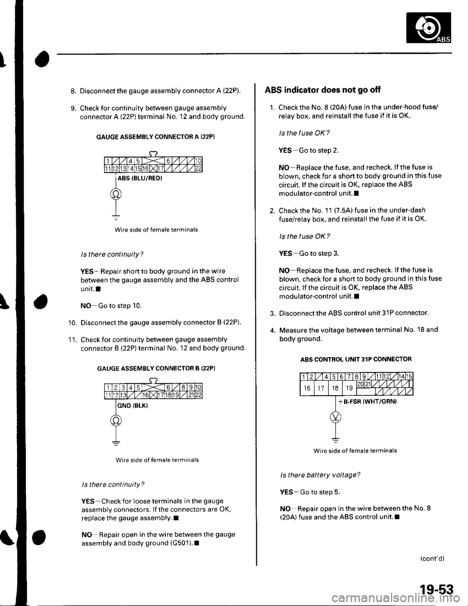
Disconnect the gauge assembly connector A (22P).
Check for continuity between gauge assembly
connector A {22P) terminal No, 12 and body ground.
GAUGE ASSEMBLY CONNECTOR A (22P)
Wire side of female terminals
ls there continuity?
YES- Repair shon to body ground in the wire
between the gauge assembly and the ABS control
unit.l
NO Go to step 10.
Disconnect the gauge assembly connector B (22P).
Check for continuity between gauge assembly
connector B (22P) terminal No. 12 and body ground.
GAUGE ASSEMBLY CONNECTOR B (22PI
Wire side ol Iemale terminals
ls there continuity?
YES Check for loose terminals in the gauge
assembly connectors. lf the connectors are OK,
replace the gauge assembly.l
NO Repair open in the wire between the gauge
assembly and body ground (G501).1
'10.
11.
3.
ABS indicator does not go off
1. Checkthe No. 8 (20Alfuse in the under-hood fuse/
relay box, and reinstall the fuse if it is OK.
ls the fuse OK?
YES Go to step 2.
NO-Replace the fuse, and recheck. lf the fuse is
blown, check for a shon to body ground in this fuse
circuit. ll the circuit is OK, replace the ABS
modulator-control unit. I
Check the No. 11 (7.5A) fuse in the under-dash
fuse/relay box, and reinstall the fuse if it is OK.
ls the f use OK?
YES Go to step 3.
NO Replace the fuse, and recheck. If the fuse is
blown, check for a short to body ground in this fuse
circuit. lf the circuit is OK, replace the ABS
modulator-control unit. I
Disconnect the ABS control unit 31P connector.
Measure the voltage between terminal No. l8 and
body ground.
A8S CONTROL UNIT3lP CONNECTOR
ls there battery voltage?
YES-Go to step 5.
NO Repair open in the wire between the No. 8
(20A) fuse and the ABS control unit.l
(cont'd)
Wire side of female terminals
19-53
Page 721 of 1139
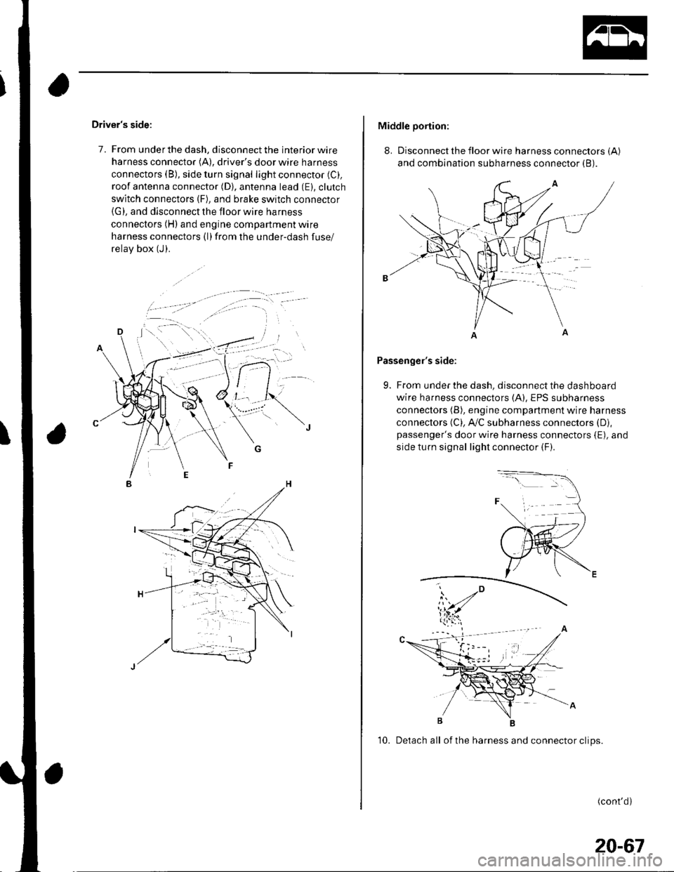
Driver's side:
7. From under the dash, disconnect the interior wire
harness connector (A), driver's door wire harness
connectors (B), side turn signal light connector (C).
roof antenna connector (D), antenna lead (E). clutch
switch connectors (F), and brake switch connector(G), and disconnect the floor wire harness
connectors (H) and engine compartment wire
harness connectors (l)from the under-dash fuse/
relav box (J).
Middle portion:
8. Disconnect the floor wire harness connectors (A)
and combination subharness connector (B).
Passenger's side:
9. From under the dash, disconnect the dashboard
wire harness connectors (A), EPS subharness
connectors (B), engine compartment wire harness
connectors (C), A,/C subharness connectors (D),
passenger's door wire harness connectors {E), and
side turn signal light connector (F).
10. Detach all of the harness and connector clips.
(cont'd)
20-67