fuse box HONDA CIVIC 2002 7.G Manual Online
[x] Cancel search | Manufacturer: HONDA, Model Year: 2002, Model line: CIVIC, Model: HONDA CIVIC 2002 7.GPages: 1139, PDF Size: 28.19 MB
Page 880 of 1139
Under-dash Fuse/Relay Box
Removal and Installation
SRS components are located in this area. Review the
SRS component locations {see page 23-13) andprecautions and procedures (see page 23-14) in the SRS
section before performing repairs or service.
Removal
1. Make sure you have the anti-theft code for the radio,
then write down the frequencies for the radio's
preset buttons.
2. Disconnectthe battery negative cable, then
disconnect the positive cable, and wait at least
three minutes.
3. Remove the driver's dashboard lower cover (see
page 20-59).
4. Disconnect the connectors from the fuse side of the
under-dash fuse/relay box.
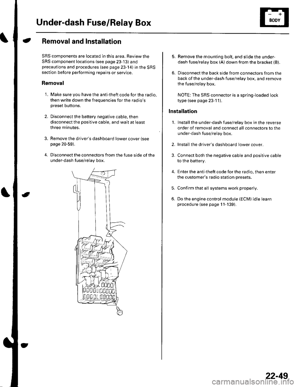
5. Remove the mounting bolt, and slide the under-
dash fuse/relay box (A) down from the bracket {B).
6. Disconnect the back side from connectors from the
back of the under-dash fuse/relay box, and remove
the fuse/relay box.
NOTE:The SRS connector is a spring-loaded lock
type (see page 23-1 1).
lnstallation
1. Installthe under-dash fuse/relay box in the reverse
order of removal and connect all connectors to the
under-dash fuse/relay box.
2. Installthe driver's dashboard lower cover.
3. Connect both the negative cable and positive cable
to the battery.
4. Enter the anti-theft code for the radio, then enter
the customer's radio station presets.
5. Confirm that all systems work properly,
6. Do the engine control module (ECM) idle learn
procedure (see page 11-139).
22-49
Page 884 of 1139
lgnition Switch
Test
SRS components are located in this area. Review the
SRS component locations (see page 23-13) andprecautions and procedures {see page 23-'l4) in the SRS
section before performing repairs or service.
1, Remove the driver's dashboard lower cover {seepage 20-59).
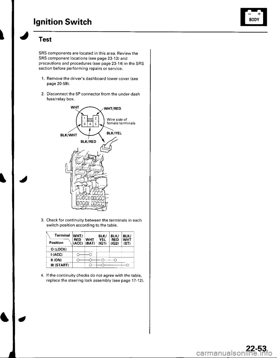
2. Disconnect the 5P connector from the under-dash
fuse/relay box.
WHT/RED
Wire side offemale terminals
BLK/WHTBLK/YEL
BLK/RED
Check for continuity between the terminals in each
switch position according to the table.
Terminal
p.J,i""-\
WHT/RED(ACC)
BLK/WHT YEL(BAT) flGl)
BLK/REDtrc2t
BLK/WHT(sr)
o (LocK)
| (ACC)o---o
[ (oN)
III (START)
c)-_H
o_H
lf the continuity checks do not agree with the table,
replace the steering lock assembly (see page'17-121.
22-53
Page 887 of 1139
Gauges
Self-diagnostic Procedure
The gauge assembly has a self-diagnosis function.. The Beeper Drive Circuit Check. The Indicator Drive Circuit ChecL. The LCD Segments Check. The Gauges Drive Circuit Check (Speedometer, Tachometer, Fuel gauge, Coolant temperature gauge). The Communication Line Check (the coolanttemperature signal line between the gauge and ECM)
NOTE: Indicators are also controlled via the communication line.
Entering the self-diagnosis f unction:
Before doing the self-diagnosis function, check the No. 9 (10A) fuse in the under-hood fuse/relay box and No. 10 {7.5A)fuse in the under'dash fuse/relay box.
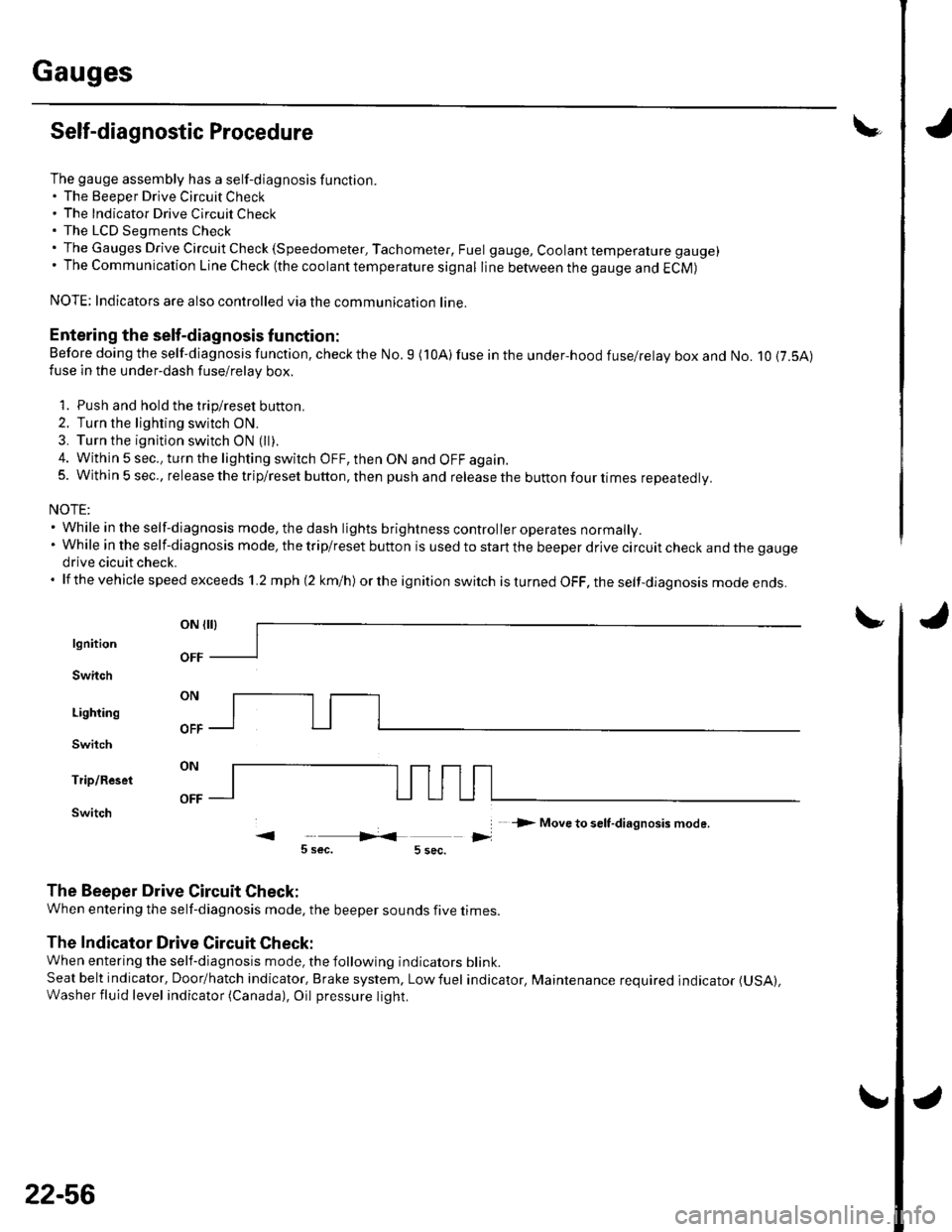
1. Push and hold the trip/reset button.
2. Turn the lighting switch ON.
3. Turn the ignition switch ON (ll).
4. Within 5 sec., turn the lighting switch OFF, then ON and OFF again.5. Within 5 sec., release the trip/reset button, then push and release the button four times reDeatedlv.
NOTE:. While in the self-diagnosis mode, the dash lights brightness controller operates normally.'Whileintheself-diagnosismode,thetrip/resetbuttonisusedtostartthebeeperdrivecircuitcheckandthegauge
drive cicuit check.. lf the vehicle speed exceeds 1.2 mph 12 km/h) orthe ignition switch is tu rned OFF, the self,diag nosis mode ends.
oN flrl
lgnition
Switch
Lighting
Switch
Trip/Reset
Switch-> Move to selt-diagnosis mode.
5 sec.5 sec.
The Beeper Drive Circuit Check:
When entering the self-diagnosis mode, the beeper sounds five times
The Indicator Drive Circuit Check:
When entering the self-diagnosis mode, the following indicators blink.
Seat belt indicator, Door/hatch indicator, Brake system, Lowfuel indicator, Maintenance required indicator (USA),
Washer fluid level indicator (Canada), Oil pressure light.
v
OFF
22-56
Page 891 of 1139
J
a
Gauges
I
No2il5AlFUSEilnlh.undi hooq DASHllu!./rcl.ybox r LGHTS
YY
tltl
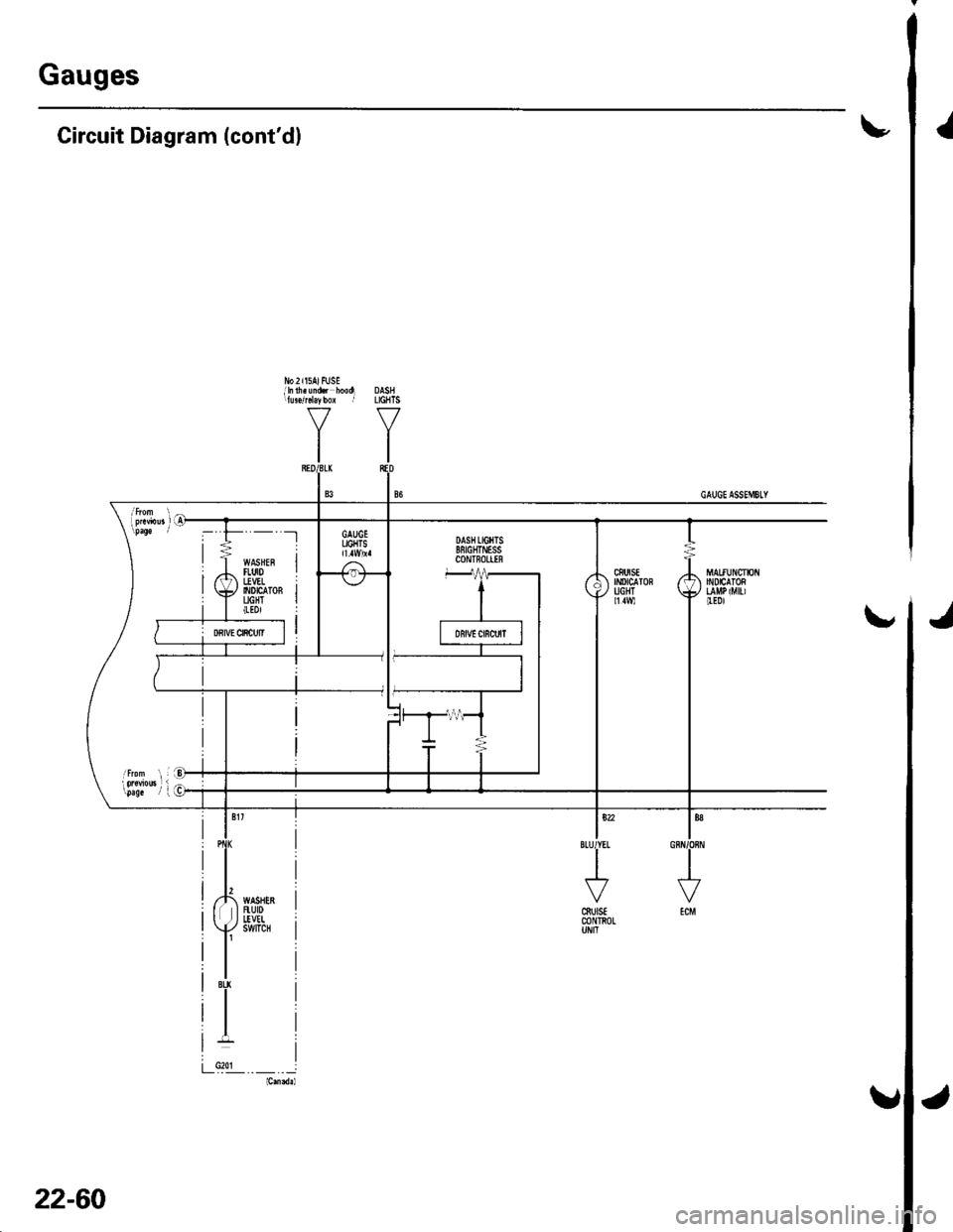
Circuit Diagram (cont'dl
ls?2IBLUIYEL
I
J
cSutsEm n0L
'- -t
WASHEFItut0I!VEL6t0tc ToRUGHT(tDl
22-60
Page 895 of 1139
Gauges
2.
3.
Gauge Assembly Replacement
1.Remove the instrument panel (see page 20-59),
then remove the upper column cover {see page 17-
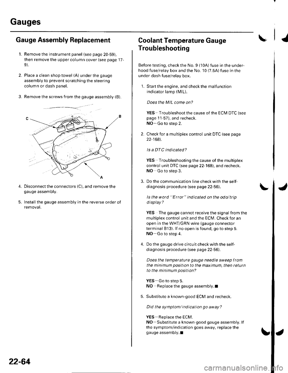
Place a clean shop towel (A) under the gauge
assembly to prevent scratching the steering
colum n or dash panel.
Remove the screws from the gauge assembly (B).
Disconnect the connectors (C), and remove thegauge assemDry.
Installthe gauge assembly in the reverse order of
removal.
Coolant Temperature Gauge
Troubleshooting
Before testing, check the No. I { 10A) fuse in the under-
hood fuse/relay box and the No. '10 (7.5A) fuse in the
under dash fuse/relay box.
1. Start the engine, and check the malfunction
indicator lamp (MlL).
Does the MIL come on?
YES- Troubleshoot the cause of the ECM DTC (see
page 1 1-57), and recheck.
NO-Go to step 2.
2. Check for a multiplex control unit DTC (see page
22,168).
ls a DTC ind icated?
YES Troubleshooting the cause of the multiplex
control unit DTC {see page 22-168), and recheck.
NO Go to step 3.
3. Do the communication line check with the self-
diagnosis procedure (see page 22-56).
ls the word "Error" indicated on the odo/ttip
d isplay ?
YES The gauge cannot receive the signal from the
multiplex control unit and the ECI\,4. Check for an
open in the WHT/GRN wire (gauge connector
terminal B 13). lf no open is found, go to step 5.
NO Go to step 4.
4. Do the gauge drive circuit check with the self-
diagnosis procedure (see page 22-56).
Does the temperature gauge needle sweep lrom
the minimum position to the maximum, then tetutn
to the minimum position?
YES Go to step 5.
NO Replace the gauge assembly.l
5. Substitute a known-good ECM and recheck.
Did the symptom/ ind ication go away?
YES Replace the ECM.
NO Substitute a known good gauge assembly. lf
the symptom/indication goes away, replace thegauge assembly.l
4.
22-64
Page 896 of 1139
IVehicle Speed Signal Circuit Troubleshooting
Special Tools Required:
Test Harness 07LAJ-PT3020A
Before testing, inspect the No. 4 (10A) and No. 10 (7.5A)
fuses in the under-dash fuse/relay box.
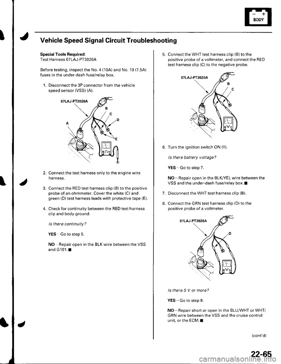
1. Disconnect the 3P connector from the vehicle
speed sensor (VSS) {A).
Connect the test harness only to the engine wire
harness.
Connect the RED test harness clip (B) to the positive
probe of an ohmmeter. Cover the white (C) and
green {D) test harness leads with protective tape (E).
Check for continuity between the RED test harness
clip and body ground,
ls there continuity?
YES Go to step 5.
NO Repair open in the BLK wire between the VSS
and G 101.I
3.
4.
5. Connect the WHT test harness cliD (B) to the
positive probe of a voltmeter, and connect the RED
test harness clip (C) to the negative probe.
Turn the ignition switch ON (ll).
le thara h2ltarv v^ltada?
YES-Go to step 7.
NO Repair open in the BLK,/YEL wire between the
VSS and the under-dash fuse/relay box.l
Disconnect the WHT test harness clip (B).
Connect the GRN test harness clip {D) to the
positive probe of a voltmeter.
Is there 5 V or more?
YES- Go to step 9.
NO Repair short or open in the BLUMHT or WHT/
GRN wire between the VSS and the cruise control
unit, or the ECM.I
(cont'd)
7.
8.
22-65
Page 899 of 1139
Exterior Lights
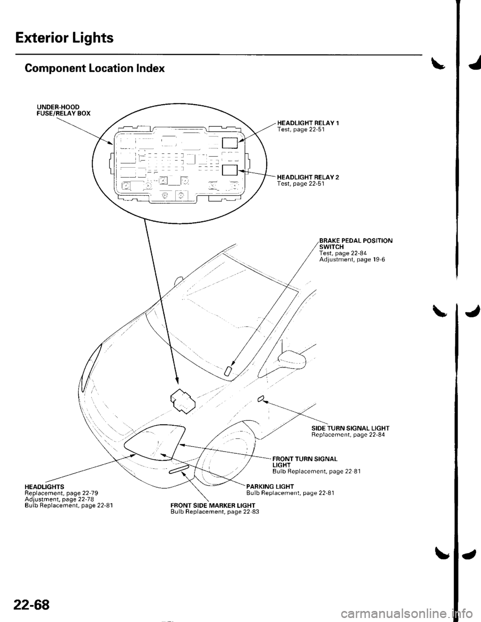
Gomponent Location Index
UNDER.HOODFUSE/RELAY BOX
\/
HEADLIGHTSReplacement, page 22 79Adjustment. page 22-78Eulb Replacement, page 22-81
HEADLIGHT RELAY 1Test, page 22-51
HEADLIGHT RELAY 2Test, page 22-5'l
0/
FRONT SIDE MARKER LIGHTBulb Replacement, page 22 83
BRAKE PEDAL POSITIONswtTcHTest, page 22-84Adjustment, page l9'6
SIDE TURN SIGNAL LIGHTReplacement, page 22-84
FRONT TURN SIGNALLIGHTBulb Beplacement, page 22 81
PARKING LIGHTBulb Replacement, page 22-81
22-68
Page 901 of 1139
Exterior Lights
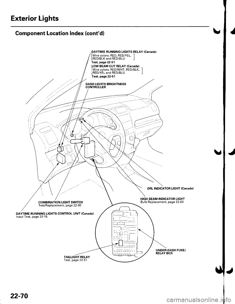
Component Location Index (cont'dl!
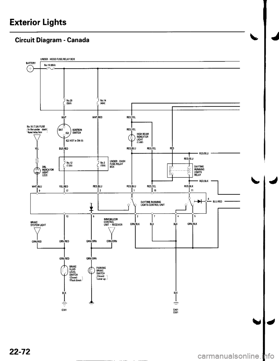
DAYTIME RUNNING LIGHTS RELAY {Canadal[Wire colors: RED, REDryEL, ILRED/BLK and RED/BLU ITest, page 22-51
_LOW BEAM CUTRELAY {Canadal _Wire colorsr REDMHT, RED/BLK, ILREDryEL and RED/BLU ITest, page 22-51
DASH LIGHTS BRIGHTNESSCONTROLLER
/
COMBINATION LIGHT SWITCHTesVReplacement, page 22-80
oAYTIME RUNNING LIGHTS CONTROL UNIT lcanada)Input Test, page 22-76
DRL INDICATOR LIGHT {Canadal
HIGH BEAM INDICATOR LIGHTBulb Replacement, page 22-63
UNDER.DASH FUSE/RELAY BOX
:' --,': - '
' i,-'-'l
..i \
I t- -
22-70
Page 903 of 1139
J
J
Exterior Lights
tCircuit Diagram - Canada
t
cl.1G501G301
UNOEN HOOO FUSE/8ELAY BOX
No l9l80Al
J
) to.o- i50AlNo.1'lloa)
No.!0(7 SAlr
V
I'l'
I
usE /',d.3hl I EAr
\
BU1
IT WHT
t-\
rc|'/moN. rcz/ swfrcH
v
I G2 Hor in 0N {ll)
IBED
ED RED,I
I'2
I*01
I
fifi li{*1l,.H'� I
I
ItU RED/,l
-_l
-- ,'orrro". ) INDICAIOF-/ l'lcli;
BLUl
RE=.|
A DNL) No12i l7.5AlDAYTIMEBUNNINCLIGHTSEfLAY\y
IIHT/BIIn
TIGHTluDl
12REt0t1
--t
lT
,{ oorr,",rr.,ro { r-
I I
uctrrscournoLu,'r"
J l
SLU/BID8
SYSIIM UGHI
VYIGNfl/FEO GRI\
(
!3
/NED
II
I
f'r 88A(EI FiUrD2 , LTVEL[./ SWITCH
I
'nddoM
I
i
||MoS|UZEnCONTNOLUNIT RECEIVEB
17
YI
3
BI( BIBIG8N
F PANKNG; } BNAXE+./ swrTcH
i
J\,
22-72
Page 905 of 1139
Exterior Lights
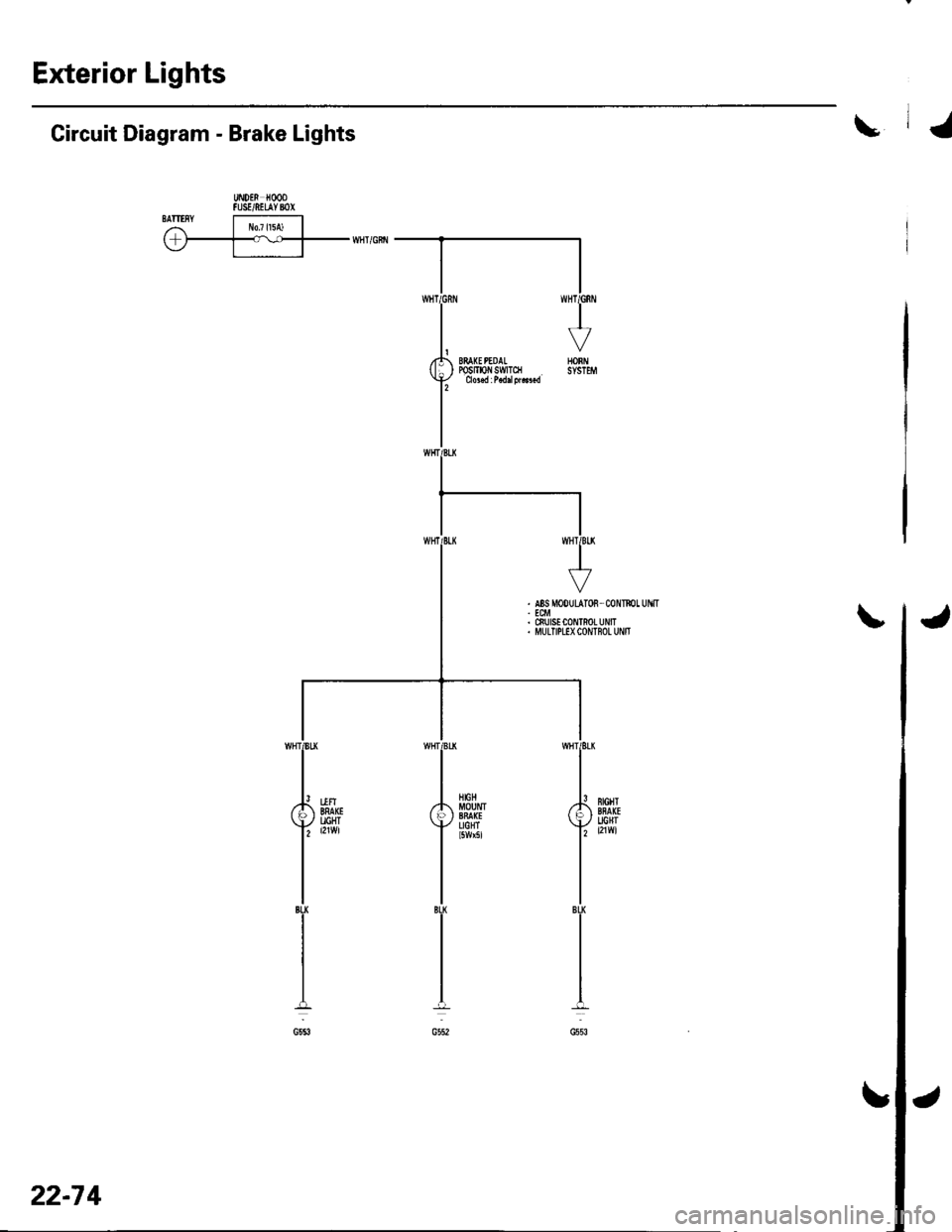
\Circuit Diagram - Brake Lights
UiDEN HOODFUSE/NEUYBOXSATIISYI r!o7l15A) | ,r-T-v--rrni'citr
22-7 4