turn signal HONDA CIVIC 2002 7.G Repair Manual
[x] Cancel search | Manufacturer: HONDA, Model Year: 2002, Model line: CIVIC, Model: HONDA CIVIC 2002 7.GPages: 1139, PDF Size: 28.19 MB
Page 916 of 1139
Turn Signal/Hazard Flasher
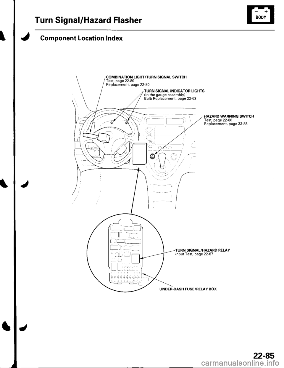
Component Location Index
COMBINATION LIGHT/TURN SIGNAL SWITCHTest, page 22-80Beplacement, page 22-80
TURN SIGNAL INDICATOR LIGHTS(ln the gauge assembly)Bulb Replacement, page 22'63
HAZARD WARNING SWITCHTest, page 22-88Replacement, page 22-88
TURN SIGNAL/HAZARD RELAYInput Test, page 22-87
UNDER.DASH FUSE/RELAY BOX
22-85
Page 917 of 1139
Turn Signal/Hazard Flasher
UNDff HOOD FUSUftIIY 8OX
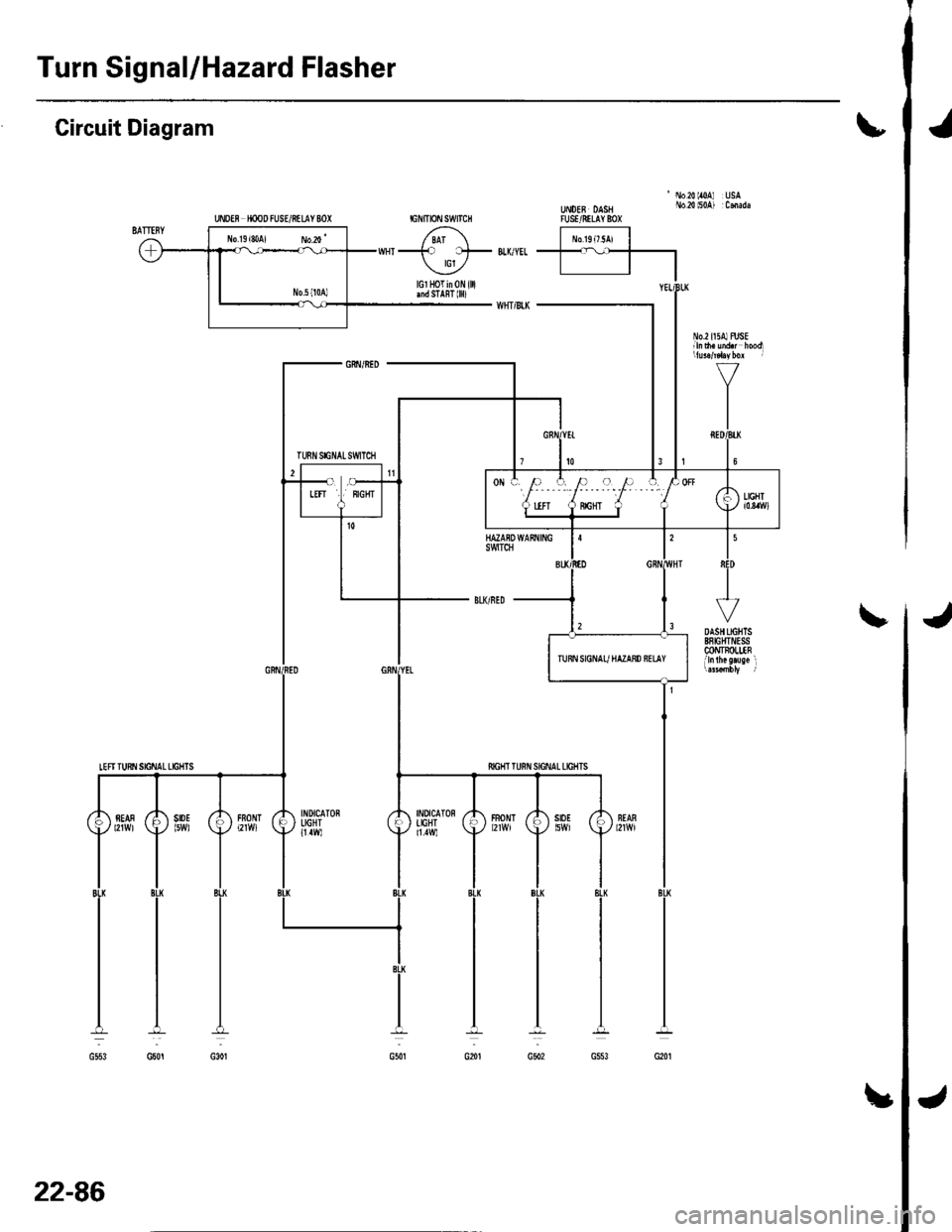
Circuit Diagram\
'No20lr0A USAUt oEB DASH No.2{ l50A) :CmadaTUSVRILAY 8OX
J
INDICATONIIGHT11.1W)
fiIGHT T
FBONT
22-86
!
Page 918 of 1139
Turn Signal/Hazard Relay Input Test
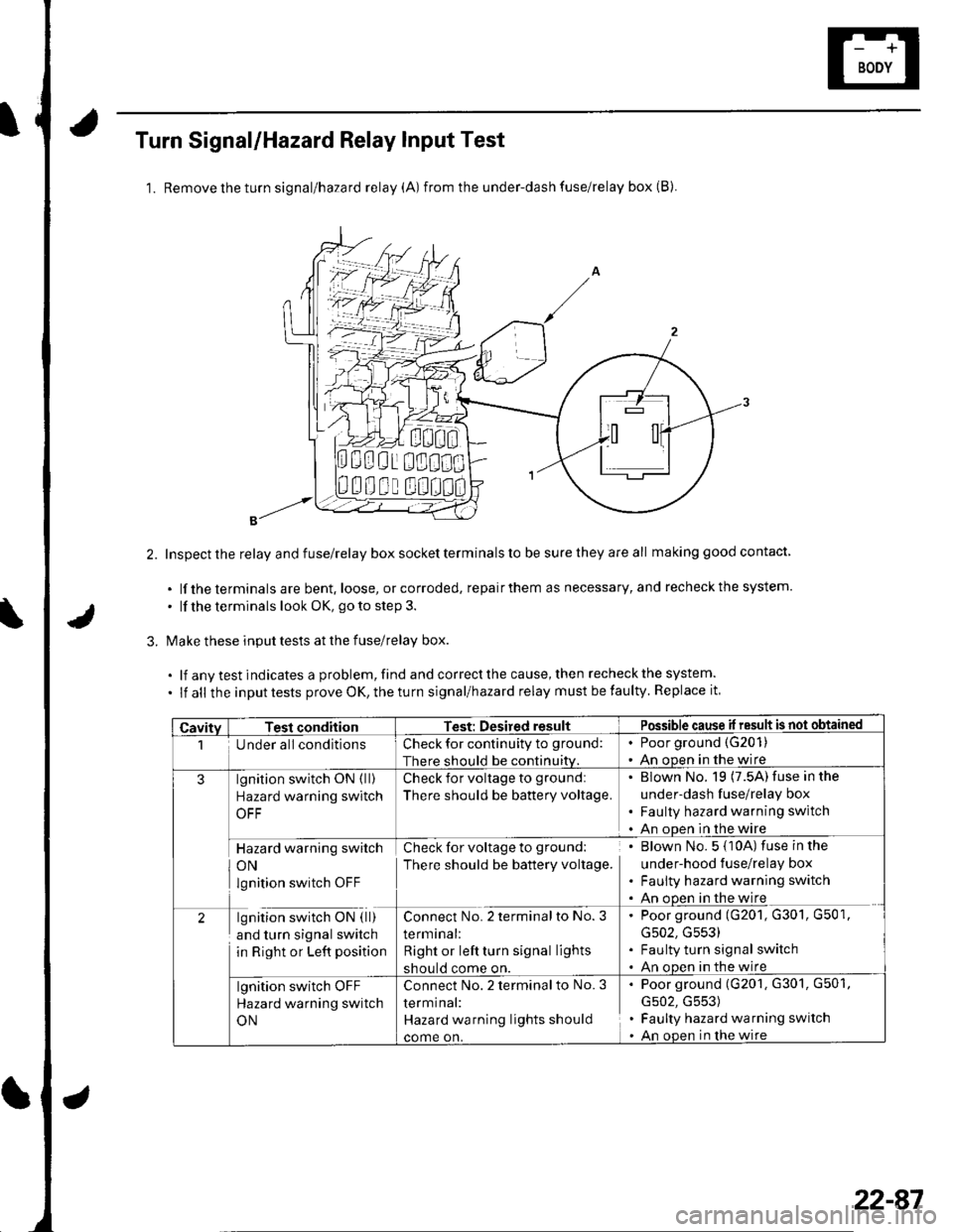
1. Removetheturn signal/hazard relay (A) from the under-dash fuse/relay box (B).
Inspect the relay and fuse/relay box socket terminals to be sure they are all making good contact
. lf the terminals are bent. loose, or corroded, repairthem as necessary, and recheckthe system.
. lf the terminals look OK, go to step 3.
Make these input tests at the fuse/relay box.
.lfanvtestindicatesaproblem,findandcorrectthecause,thenrecheckthesystem.
. lf all the inputtests prove OK,theturn signal/hazard relay must befaulty. Replace it
000i 0!1000
00u! u0
CavitvTesl conditionTest: Desired resultPossible cause il result is not obtained
1Under all conditionsCheck for continuity to ground:
There should be continuiw.
. Poor ground (G201)
. An ooen in the wire
3lgnition switch ON ( ll)
Hazard warning switch
OFF
Check for voltage to ground:
There should be battery voltage.
' Blown No. 19 (7.5A) fuse in the
under-dash fuse/relay box. Faulty hazard warning switch. An ooen in the wire
Hazard warning switch
ON
lgnition switch OFF
Check for voltage to ground:
There should be battery voltage.
. Blown No. 5 {10A) fuse in the
under-hood fuse/relay box. Faulty hazard warning switch. An ooen in the wire
2lgnition switch ON ( ll)
and turn signal switch
in Right or Left position
Connect No. 2 terminalto No. 3
terminal:
Right or left turn signal lights
should come on.
. Poor ground (G201, G301, G501,
G502, G553). Faulty turn signal switch. An oDen in the wire
lgnition switch OFF
Hazard warning switch
ON
Connect No.2 terminal to No. 3
termrnal:
Hazard wa rning lights should
come on.
. Poor ground (G201, G301, G501,
G502, G553). Faulty hazard warning switch. An open in lhe wire
22-87
Page 919 of 1139
Turn Signal/Hazard Flasher
1.
2.
Hazard Warning Switch Test
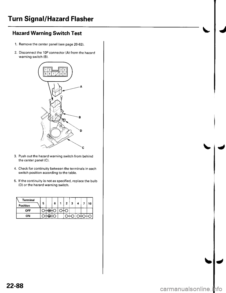
Remove the center panel (see page 20-62).
Disconnect the 10P connector (A) from the hazard
warning switch (B).
4.
Push out the hazard warning switch from behind
the center panel (C).
Check for continuity between the terminals in each
switch position according to the table.
lf the continuity is not as specified, replace the bulb(D) orthe hazard warning switch.
Termin6l
;;;-_-\124710
OFF
ON@
3.
22-88
Page 994 of 1139
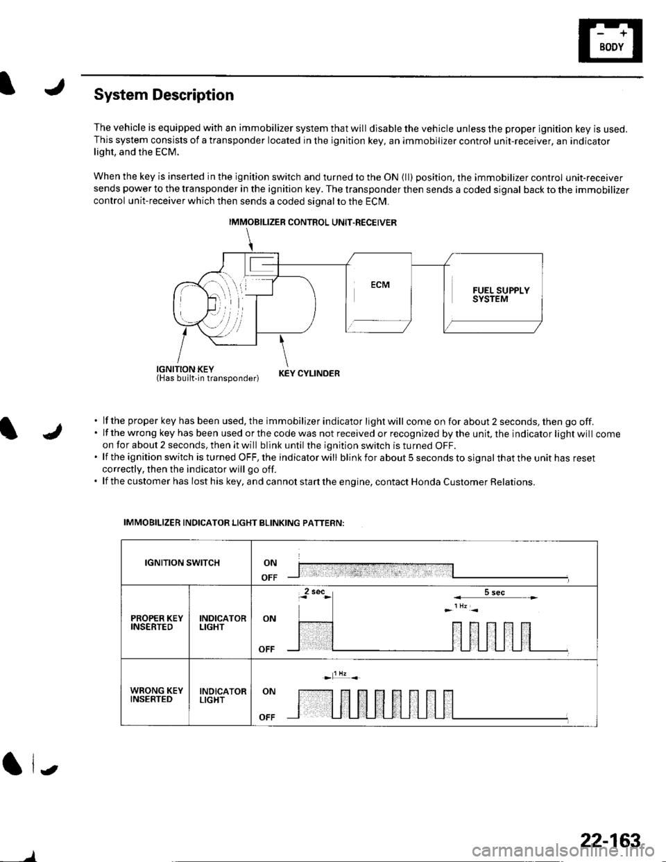
System Description
The vehicle is equipped with an immobilizer system that will disable the vehicle unless the proper ignition key is used.This system consists of a transponder located in the ignition key, an immobilizer control unit-receiver, an indicatorlight, and the ECM.
When the key is inserted in the ignition switch and turned to the ON {ll) position, the immobilizer control unit-receiversends power to the transponder in the ignition key. The transponder then sends a coded signal back to the immobilizer
control unit-receiver which then sends a coded signal to the ECI\4.
iEl'JUiliii'tlun"oona"|.r KEYCYLTNDER
lf the proper key has been used, the immobilizer indicator light will come on for about 2 seconds, then go off.lf the wrong key has been used or the code was not received or recognized by the unit, the indicator light will comeon for about 2 seconds, then it will blink until the ignition switch is turned OFF.lf the ignition switch is turned OFF, the indicator will blink for about 5 seconds to signal that the unit has reset
correctly, then the indicator will go off.
lf the customer has lost his key, and cannot start the engine, contact Honda Customer Relations.
IMMOBILIZER INDICATOR LIGHT BLINKING PATTERN:
IGNITION SWITCHON
OFF
PROPER KEYINSERTEDINDICATORLIGHTON
WRONG KEYINSERTEDINDICATORLIGHTON
OFF
(| i.,
IMMOBILIZER CONTROL UNIT.RECEIVER
)
22-163
Page 1002 of 1139
ISystem Descriptions
The Multiplex Control System has four internal
functions:. Multiplexing (send multiple signals over sharedwtres). Wake up/sleep (runs at full power only on demand toreduce battery draw). Fail-safe (fixes or ignores faulty signals). Self-diagnosis (Mode 1 for the system, Mode 2 for
input lines)
The system controls the function of these circuits:. Entry lightcontrol (ignition key lightandceiting light). Wiper/washer intermittent wipe and park functions. Keyless/power door lock. Meter assembly, temperature gauge, and indicator
lights. HVAC (compressor and fan control). Key-in reminder. Headlight reminder. Seatbelt reminder
JI
/ar
22-171
Multiplex Communication
To reduce the number of wire harnesses, digital signals
are sent via shared multiplex communication linesrather than sending normal electrical signals throughindividual wires.. The input signals from each switch are converted todigital signals at the central processing unit (CpU).. The digital signalsaresentfromthetransmitting unitto the receiving unit as serial signals.. The transmitted signal is converted to a switch signalat the receiving unit, and it operates the related
component or monitors a swltch.. There are exclusive communicalion lines between
the ECM, the gauge assembly, and the under,dash
fuse/relay box.
Wake-up and Sleep
The multiplex control system has "wake-up" and"sleep" functions to decrease parasitic draw on the
battery when the ignition switch is OFF.. ln the sleep mode, the multiplex control unit stops
functioning (communication and CPU control) when it
is not necessary for the system to operate.. As soon as any operation is requested (for example, adoor is unlocked), the related control unit in the sleep
mode immediately wakes up and begins to function.. When the ignition switch is turned OFF, and the
driver's or front passenger's door is opened, then
closed, there is about a 10 second delay before the
control unit goes from the wake-up mode to the sleepmode.. lf any door is open, the sleep mode will not function.. lf a key is in the ignition switch, the sleep mode will
not function.. When in sleep mode, the draw is reduced from
70 80 mA to less than 10 mA.
Fail-safe
To prevent improper operation, the multiplex controlsystem has a fail-safe function. In the fail-safe mode,
the output signal js fixed when any part of the systemmalfunctions (for example a faulty control unit orcommunication line).
Each control unit has a hardware fail-safe function thatfixes the output signal when there is any CPUmalfunction, and a software fail-safe function thatignores the signal from the malfunctioning control unitand allows the system to operate normally.
Page 1098 of 1139
)
)
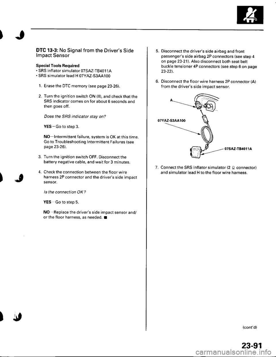
DTC 13-3: No Signal from the Driver's Side
lmpact Sensor
Special Tools Required. sRs inflator simularor 07SAZ-TB4011A. SRS simulator lead H 07YM-S3AA100
1. Erasethe DTC memory (see p age 23-261.
2. Turn the ignition switch ON (ll), and check that the
SRS indicator comes on for about 6 seconds and
then goes off.
Does the SRS indicator stay on?
YES - Go to step 3.
NO Intermittent failure, system is OK at this time.
Go to Troubleshooting lntermittent Failures (see
page 23-261.
3. Turn the ignition switch OFF. Disconnect the
battery negative cable, and wait for 3 minutes.
4. Check the connection between the floor wire
harness 2P connector and the driver's side impact
sensor.
ls the connection OK?
YES Go to step 5.
NO-Replace the driver's side impact sensor and/
or the floor harness, as needed. I
)
5. Disconnectthe driver's side airbag and frontpassenger's side airbag 2P connectors (see step 4
on page 23-21). Also disconnect both seat belt
buckle tensioner 4P connectors (see step 6 on page
23-22).
6. Disconnect the floor wire harness 2P connector {A}from the driver's side impact sensor.
07sAz-TB4011A
7. Connect the SRS inflator simulator (2 Q connector)
and simulator lead H to the floor wire harness.
(cont'd)
23-91
Page 1101 of 1139
sRs
DTC Troubleshooting (cont'dl
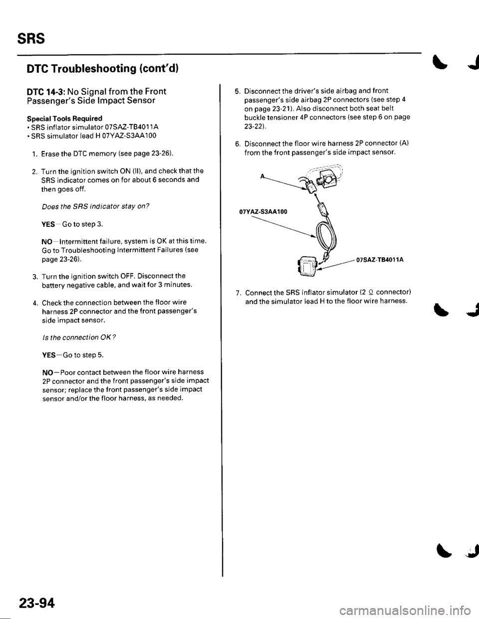
DTC 14-3: No Signal from the Front
Passenger's Side lmpact Sensor
SpecialTools Required. SRS inflator simulator 07SAZ-TB401'lA. SRS simulator lead H 07YAZ'S3AA100
1. Erasethe DTC memory (see page 23-26).
2. Tu rn the ignition switch ON (ll), and check that the
SRS indicator comes on for about 6 seconds and
then goes off.
Does the SBS indicator stay on?
YES Go to step 3.
NO Intermittent failure, system is OK at this time.
Go to Troubleshooting Intermittent Failures (see
page 23-26).
3. Turn the ignition switch OFF. Disconnectthe
battery negative cable, and wait for 3 minutes.
4. Check the connection between the floor wire
harness 2P connector and the front passenger's
side lmpact sensor.
Is the connection OK?
YES-Go to step 5.
NO- Poor contact between the floor wire harness
2P connector and the front passenger's side impact
sensor; replace the front passenger's side impact
sensor and/or the floor harness, as needed.
23-94
5.Disconnectthe driver's side airbag and front
passenger's side airbag 2P connectors (see step 4
on page 23-21). Also disconnect both seat belt
buckle tensioner 4P connectors (see step 6 on page
23-22t.
Disconnect the floor wire harness 2P connector {A)
from the front passenger's side impact sensor.
07sAz-TB4o11A
7. Connect the SRS inflator simulator (2 0 connector)
and the simulator lead H to the floor wire harness.
Page 1139 of 1139
SuspensionAdjustment................-............................184 VComponent Location Index................. 20-17
Windshield GlessReplacement............-..............-............. 20 19
Synchro Ring, Triple-coneInspection...............-..........................1339 ValveGuides
Synchro SleeveInspectaon/Reassemb1y ....................... 13 39
Inspection ............-.-................................ 6 32Beplacement ..........-................................ 6 33 Wiper Intermittent Control Unit,Rear WindowInput Test
T
Valve SeatsRepair ...................................................... 6 35.....22-134
WiDer Motor, Rear WindowRep1acement....................................... 22-1 46Adjustment .-.-.......Removal ...-...-......................................-... 6-31 WiDer Motor, windshield6-9
.....6-32 Test.......-..........-.....-.............................22-143Taillight
ThermostaiTest ........................
Inspec!on
Vehicle Speed Signal Circuit
VTC System
Wiper/WasheI
Wi.ing System
10 4 Troubleshooting .....-... ..........................22-65 Component Location In dex ..............22-134Replacement.....-...-....... ...................... 10 IvssThrottle BodyTest ..................Removal/lnstallation .. . . . . . .. ... 11-'165 VTC ActuatorDisassembly/Feassemb|y................-11-166 Inspection
Circuit Diagram .......................... 22-136, 131
Replacement -.............. ............ .............22 61 Wiper/Washor SwitchTesVReplacement .............................. 22-1 40
.................68 WireHarnesses
11-160
Replacement ........................................... 6 24 (Seefirstpageofthislndex)Throttle CableAdjustment ...... ...-.................... 11163 VTC Oil ConlrolSolenoid ValveRemoval/1nsta11ation..........................11164 Removal....-...-... |1-127 HowtoIn{ormation ...............................223Belay and Control UnitLocations .-....-.............. -.-.-....- 22-7, 4, 1 1, 12Beplacement.........-............................... 1767 ComponentLocationlndex.............. 11-117Tie-rod Ball Joint Boots
lnstallation
Replacement
Turn Signal/Hazard Relay
tsTiming/Cam ChainVTEC Solenoid Valve...612 Femoval/lnspection....-......................11-128................ 6 15
Timing/Cam Chain Auto-tensionelRemoval/1nsta11ation..............................6-19 W
Troubleshooting{See first page ot this Index)
Turn Signal Light
Timing/Cam Chain CaseOil SealInstallation......................-......................6,21 Washer Fluid Level SwitchTesVReplacement .............................. 22 1 44Trailing ArmsRemoval/lnstallation .............. . . . . ..... 18 33 Washer Fluid ReservoirReplacement ....................................... 22-1 46tnmComponent Location lndex ................- 20 49 Washer Motor, WindshieldRemoval/lnstallation ..-.......20 50,51,52,53 Test -..............-.............. ........................22 144
Washer Tube, WindshieldReplacement......-...-............................ 22 1 47
W.ter Outlet.........22 A4 Installation ..................-........................... '10-9
InputTest........22-87 lnstallation................ 10IWeter Passage
Wheels andTires
Turn Signal/Hazard Warning Lights Water PumpComponent Location In dex .................22 85 Inspection ........................... .. . . . ....... 10 5Circu it Diagram ................-................... 22-86 Replacement .-......................................... 10 5
U
WheelBearingsInspec|ion ....................................... ....... 18 8
Wheel Speed SensorsInspection ..-..,.,.,,.,,,,,.,.,,,...................... 19-59Replac€ment ........-....... . . . . . . .. -.... 19-59UndeFdash Fuse/R€lay BoxRemoval/lnstaf lation ............................ 22-49
Upper ArmsRemoval/|nsta11ation................. ... 18-32
],sInspect|on