dtc HONDA CIVIC 2002 7.G Manual PDF
[x] Cancel search | Manufacturer: HONDA, Model Year: 2002, Model line: CIVIC, Model: HONDA CIVIC 2002 7.GPages: 1139, PDF Size: 28.19 MB
Page 338 of 1139
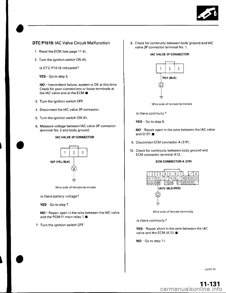
DTC Pl519: IAC Valve Circuit Malf unction
1. Resetthe ECM (see page 11-4).
2. Turn the ignition switch ON (ll)
ls DTC P 1519 indicated?
YES Go to step 3.
NO-lntermittent failure, system is OK at this time.
Check for poor connections or loose terminals at
the IAC valve and at the ECM.I
3. Turn the ignition switch OFF.
4. Disconnect the IAC valve 3P connector.
5. Turn the ignition switch ON (ll).
6. Measure voltage betlveen IAC valve 3P connector
terminal No. 2 and body ground.
IAC VALVE 3P CONNECTOR
IGP {YEL/BLK)
Wire side of female terminals
ls there battery voltage?
YES Go to step 7.
NO-Repair open in the wire between the IAC valve
and the PGM-Fl main relay 1.1
Turn the ignition switch OFF.
123
7.
8, Check for continuity between body ground and IAC
valve 3P connector terminal No. 1.
IAC VALVE 3P CONNECTOR
123
PG1 {BLK}
a.
Wire side of lemale terminals
Is there continuity?
YES-Go to step 9.
NO Repair open in the wire between the IAC valve
and G'101.1
Disconnect ECM connector A (31P)
Check for continuity between body ground and
ECM connector terminal A12.
ECM CONNECTOR A 131P)
r l2l3l4 5617s
r01l12 .// 1156 ./118192C21
da25126l27ln2930
IACV {BLK/RED}
1,)
Wire side oJ Jemale terminals
ls there continuity?
YES-Repair short in the wire between the IAC
valve and the ECM (A12).1
NO Go to step 1 1.
9.
10.
LCOnI Ol
11-131
Page 339 of 1139
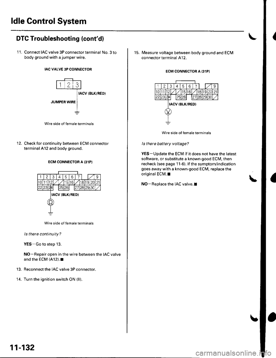
ldle Control System
(DTC Troubleshooting (cont'd)
11. Connect IAC valve 3P connector terminal No.3 to
body ground with a jumper wire.
IAC VALVE 3P CONN€CTOR
IACV IBLK/REO}
JUMPER WIRE
Wire side of female terminals
Check for continuity between ECM connector
terminalAl2 and body ground.
ECM CONNECTOR A 131P)
Wire side of female terminals
ls there continuity?
YES Go to step 13.
NO-Repair open in the wire between the IAC valve
and rhe EcM (A12).r
Reconnect the IAC valve 3P connector.
Turn the ignition switch ON (ll).
13.
14.
11-132
15. Measure voltage between body ground and ECM
connector terminal A12.
ECM CONNECTOR A 131P}
rl2l31456179
t01tl12l,/l/tc6,/ 1182C2122231?4l| 12.zil2830
IACV IBLK/RED)
Wire side ol female terminals
I s there battery voltage?
YES-Update the ECI\4 if it does not have the latest
software, or substitute a known-good ECM, then
recheck (see page 11-6). lf the symptom/indication
goes away with a known-good ECM, replace the
original ECI\4.1
NO-Replace the IAC valve.I!
Page 346 of 1139
ECM ldle Learn Procedure
The idle learn procedure must be done so the ECM can
learn the engine idle characteristics.
Do the idle learn procedure whenever you do any of
these actions:. Disconnect the battery.
Replace the ECM or disconnect its connector.
Reset the ECM.
NOTE: Erasing DTCS with the Honda PGM Tester
does not require you to do the idle learn procedure.
Remove the No.6 ECU {ECM) ( 15A) fuse from the
under-hood fuse/relay box.
Remove the No.19 baftery (80A) fuse from the under-
hood fuse/relay box.
Remove PGM-FI main relay 1.
Remove any of the wires from the under-hood fuse/
retay Dox.
Disconnect any of the connectors from the under
hood fuse/relay box.
Disconnect the connector between the engine
compartment wire harness and ECM wire harness.
Disconnect the G2 terminal from the transmission
ho u srng.
Disconnectthe G'l terminal from the body.
Disconnectthe G101 terminal from the cylinder head
cover.
Procedure:
To complete the idle learn procedure, do this:
1. Make sure all electrical items (Ay'C, audio, rear
defogger, l:ghts, etc.,) are off.
2. Start the engine, and hold it at 3,000 rpm with no
load {in neutral) until the radiator fan comes on, or
until the engine coolanttemperature reaches 194"F(90'c).
3. Let the engine idle for about 5 minutes with the
throttle fully closed.
NOTE: lf the radiator fan comes on, do not include its
running time in the 5 minutes.
11-139
Page 351 of 1139
FuelSupply System
Fuel Pressure Relieving
Before disconnecting fuel lines or hoses, relieve
pressure from the system by disconnecting the fuel
tube/quick connect fitting in the engine compartment.
1. Turn the ignition switch OFF,
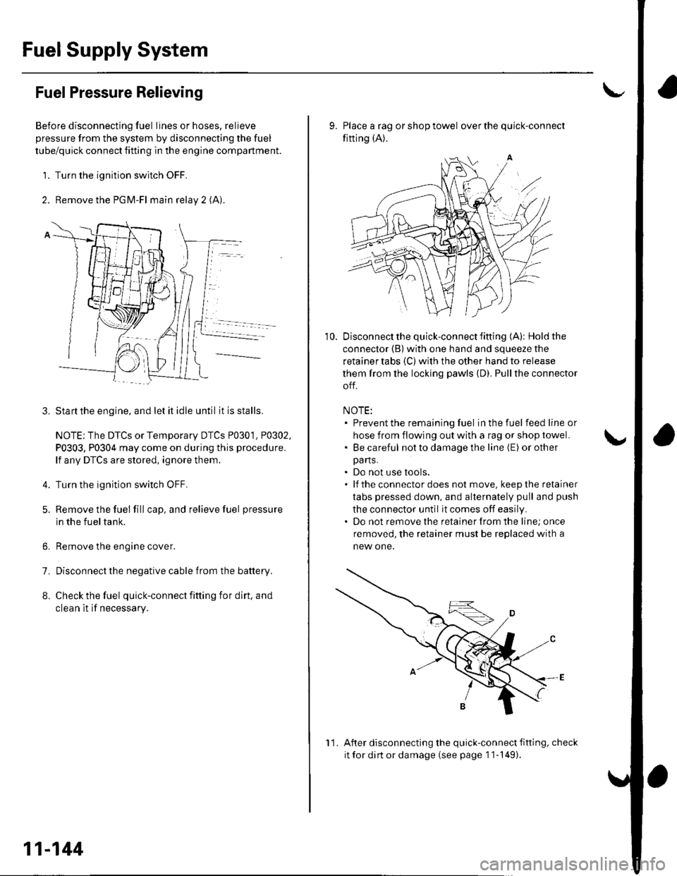
2. Remove the PGM-Fl main relay 2 (A).
Startthe engine, and let it idle until it is stalls.
NOTE: The DTCS or Temporary DTCS P0301. P0302,
P0303, P0304 may come on during this procedure.
lf any DTCS are stored, ignore them.
Turn the ignition switch OFF.
Remove the fuel fill cap, and relieve fuel pressure
in the fueltank.
Remove the engine cover.
Disconnect the negative cable from the battery.
Check the fuel quick-connect fitting for dirt, and
clean it if necessary.
3.
4.
6.
7.
8.
11-144
11
10.
9. Place a rag or shop towel over the quick-connect
fitting (A).
Disconnect the quick-connect fifting (A): Hold the
connector (B) with one hand and squeeze the
retainer tabs (C) with the other hand to release
them from the locking pawls {D). Pullthe connector
off.
NOTE:. Prevent the remaining fuel in the fuel feedlineor
hose from flowing out with a rag or shop towel.. Be careful notto damage the line (E) or other
pa rts.. Do not use tools.. lf theconnectordoes not move, keepthe retainer
tabs pressed down, and alternately pull and push
the connector until it comes off easily.. Do not remove the retainer from the line; once
removed, the retainer must be replaced with a
new one.
After disconnecting the quick-connect fifting, check
it for dirt or damage (see page 1 1-149).
Page 374 of 1139
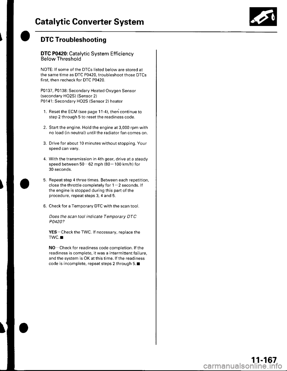
Catalytic Converter System
DTC Troubleshooting
DTC P0420: Catalytic System Efficiency
Below Threshold
NOTE: lf some of the DTCS listed below are stored at
the same time as DTC P0420, troubleshoot those DTCS
first, then recheck for DTC P0420.
P0137, P0138: Secondary Heated Oxygen Sensor(secondary HO2S) (Sensor 2)
P0141: Secondary HO2S (Sensor 2) heater
1. Reset the ECM {see page 1'l-4}, then continue to
step 2 through 5 to reset the readiness code.
2. Start the engine. Hold the engine at 3,000 rpm with
no load (in neutral) untilthe radiator fan comes on.
Drive for about l0 minutes without stopping. Your
speeo can vary.
With the transmission in 4th gear, drive at a steady
speed between 50 62 mph (80-'100 km/h) for
30 seconds.
Repeat step 4 three times. Between each repetition,
close the throttle completely for 1 2 seconds. lf
the engine is stopped during this part of the
procedure, repeat steps 3, 4 and 5.
Check for a Temporary DTC with the scan tool.
Does the scan tool indicate Temporaty DTC
P0420?
YES Check the TWC. lf necessary, replace the
TWC.I
NO Check for readiness code completion. lfthe
readiness is complete, it was a interminent failure,
and the system is OK at this time. lf the readiness
code is incomplete, repeat steps 2 through 5.1
4.
11-167
Page 375 of 1139
PCV System
DTC Troubleshooting
DTC P1505: PCV Air Leakage
1. Reset the ECM (see page 11-4).
2. Start the engine. Hold the engine at 3,000 rpm with
no load (in neutral) until the radiator fan comes on
3. Let the engine idle tor al least 40 seconds with the
throttle fully closed.
4. Check for a DTC P1505 with the scan tool
ls DTC P1505 indicated?
YES-Check these parts for vacuum leaks l
. PCV valve. PCV hose. EVAP canister purge valve
. Throttle body. Brake booster hose
NO - Intermittent failure, system is OK at this
time.l
11-168
Page 378 of 1139
DTC Troubleshooting
DTC P0451: FTP Sensor Range/Performa nce
Problem
Special Tools Required
Vacuum Pump/Gauge, 0-30 in. Hg A973X-041-XXXXX
1. Remove the fuel fill cap.
2. Turn the ignition switch ON (ll)
3. l\4onitor fuel tank pressure (FTP) sensorvoltage
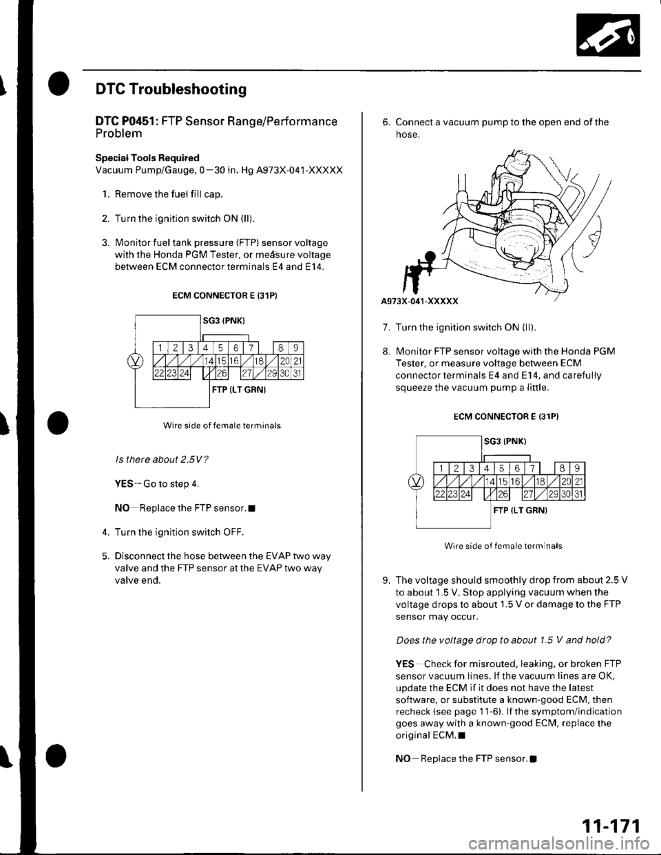
with the Honda PGM Tester, or medsure voltage
between ECM connectorterminals E4 and E14.
ECM CONNECTOR E 131P)
Wire side of female terminals
ls there about 2.5V?
YES-Go to step 4.
NO Replace the FTP sensor.I
Turn the ignition switch OFF.
Disconnect the hose between the EVAP two way
valve and the FTP sensor at the EVAP two way
valve end.
4.
5.
7.
8.
6. Connect a vacuum pump to the open end of the
hose.
Turn the ignition switch ON {ll).
l\4onitor FTP sensor voltage with the Honds PGM
Tester, or measure voltage between ECM
connector terminals E4 and E14, and carefully
squeeze the vacuum pump a little.
ECM CONNECTOR E 13lPI
Wire side of lemale terminals
The voltage should smoothly drop from about 2.5 V
to about 1.5 V. Stop applying vacuum when the
voltage drops to about 1.5 V or damage to the FTP
sensor may occur.
Does the voltage drop to about 1.5 V and hold?
YES Check for misrouted, leaking, or broken FTP
sensor vacuum lines. lf the vacuum lines are OK,
update the ECM if it does not have the latest
software. or substitute a known-good ECM, then
recheck (see page 1 1-6). lf the symptom/indication
goes away with a known-good ECM, replace the
original ECM.I
NO Replace the FTP sensor. !
9.
11-171
Page 379 of 1139
EVAP System
DTC Troubleshooting (cont'd)
DTC P0452: FTP Sensor Circuit Low Voltage
1. Check the vacuum lines at the FTP sensor for
misrouting, leakage. breakage, or clogging.
Are the vacuum lines OK?
YES Go to step 2.
NO Repair or replace vacuum lines as
necessary. I
2. Reset the ECM (see page 11-4).
3. Remove the fuelfill cap.
4. Turn the ignition switch ON (ll)
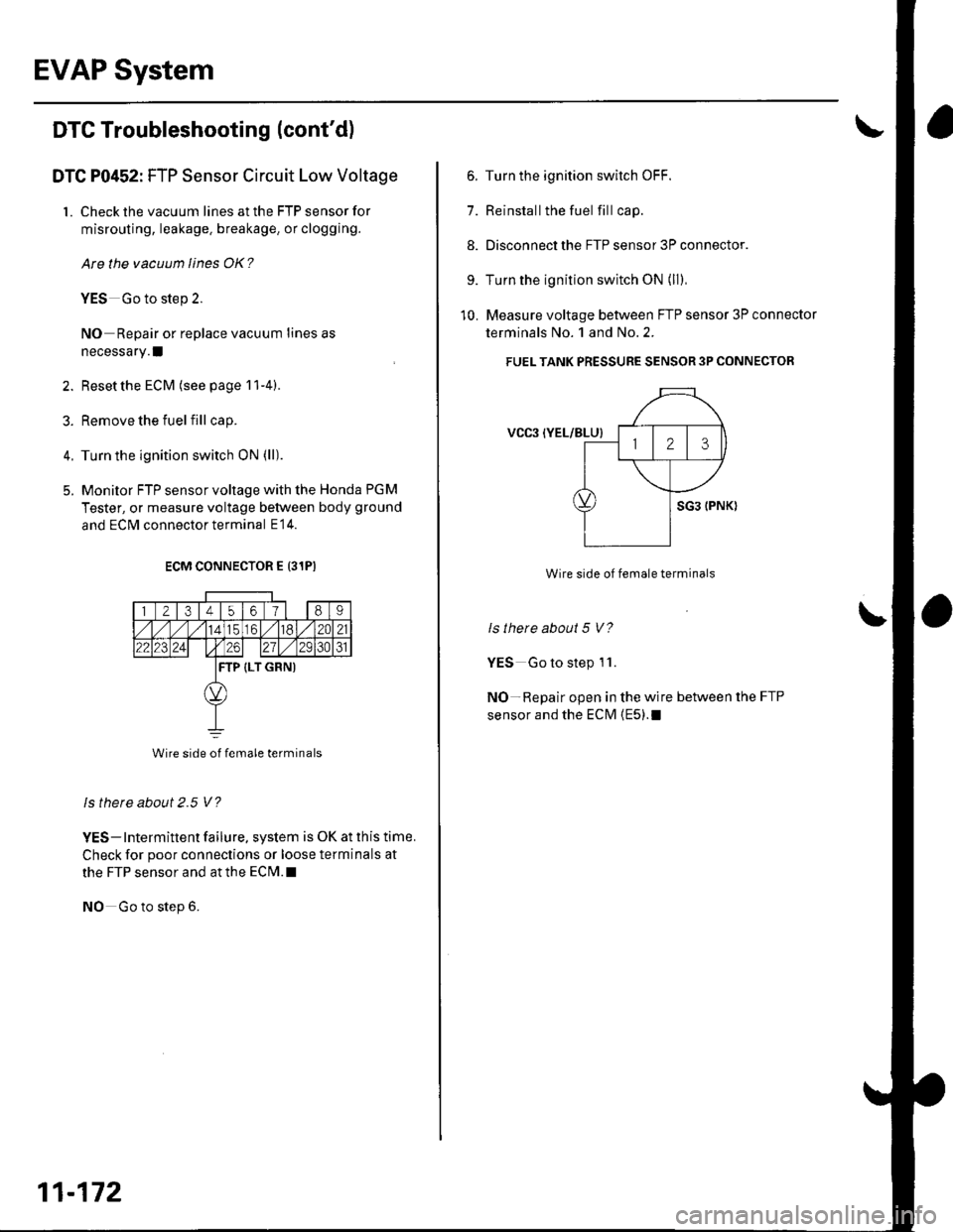
5. Monitor FTP sensor voltage with the Honda PGM
Tester, or measure voltage between body ground
and ECM connector terminal E14.
ECM CONNECTOR E 131PI
1 2t3t45o/89
././114tc61./182C21
22123241 t26271/ 2931
TP (LT GRN)
Wire side of female terminals
ls thete about 2.5 V?
YES- Intermittent failure, system is OK at this time.
Check for poor connections or loose terminals at
the FTP sensor and at the ECrM.l
NO Go to step 6.
11-172
6. Turn the ignition switch OFF.
7. Reinstallthe fuel fill cap.
8. Disconnect the FTP sensor 3P connector.
9. Turn the ignition switch ON (ll)
10. Measure voltage between FTP sensor 3P connector
terminals No. 1 and No.2.
FUEL TANK PRESSURE SENSOR 3P CONNECTOR
VCgl {YEL/BLU}
Wire side of female terminals
ls there about 5 V?
YES Go to step 1 '1.
NO-Repair open in the wire between the FTP
sensor and the ECM {E5).1
Page 380 of 1139
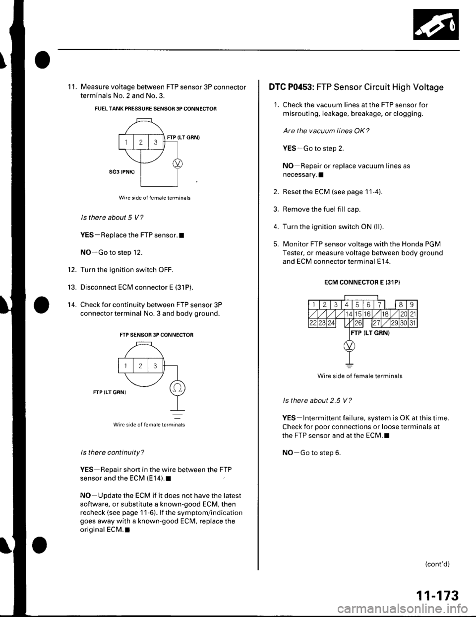
't2.
13.
14.
11. Measure voltage between FTP sensor 3P connector
terminals No. 2 and No.3.
FUELTANK PRESSUBE SENSOR 3P CONNECTOR
FTP (LT GBN)
Wire side of femaleterminals
ls there about 5 V?
YES - Replace the FTP sensor. t
NO-Go to step 12.
Turn the ignition switch OFF.
Disconnect ECM connector E (31P),
Check for continuity between FTP sensor 3P
connector terminal No. 3 and body ground.
FTP SENSOR 3P CONNECTOB
FTP (LT GRNI
Wire side of femalelerminats
ls there continuity?
YES Repair short in the wire between the FTP
sensor and the ECI\4 {E14).I
NO-Update the ECM if it does not have the latest
software, or substitute a known-good ECM, then
recheck (see page 1 1-6). lf the symptom/indicationgoes away with a known-good EClvl, replace the
original ECM.I
DTC P0453: FTP Sensor Circuit High Voltage
1. Check the vacuum lines at the FTP sensor for
misrouting, leakage, breakage, or clogging.
Are the vacuum lines OK?
YES-Go to step 2.
NO Repair or replace vacuum lines as
necessary.I
2. Reset the ECM {see page 11'4).
3. Remove the fuel fill cap.
4. Turn the ignition switch ON (ll).
5. lvlonitor FTP sensor voltage with the Honda PGM
Tester, or measure voltage between body ground
and ECM connector terminal E'14.
ECM CONNECTOR E 131PI
112134567I9
56/ t182C21
242il./29 3031
TP {LT GRN}
Wire side of female terminals
Is there about 2.5 V?
YES Intermittent failure, system is OK at this time.
Check for poor connections or loose terminals at
the FTP sensor and at the ECM.I
NO Go to step 6.
{cont'd)
11-173
Page 381 of 1139
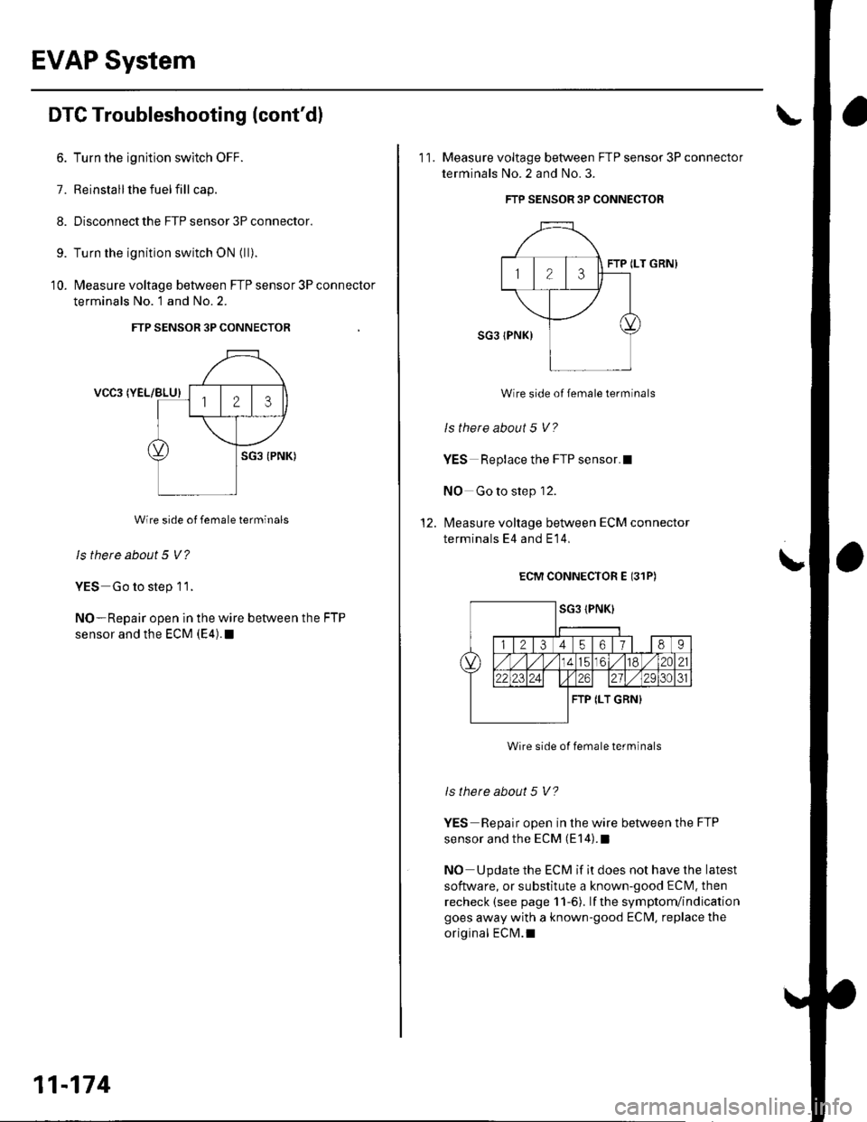
EVAP System
DTC Troubleshooting (cont'dl
6. Turn the ignition switch OFF.
7. Reinstall lhe fuel fill cap.
8. Disconnect the FTP sensor 3P connector.
9. Turn the ignition switch ON (ll).
'10. l\4easure voltage between FTP sensor 3P connector
terminals No. 1 and No.2.
FTP SENSOR 3P CONNECTOR
VCC3 (YEL/BLU)
Wire side of female terminals
ls there about 5 V?
YES Go to step 11.
NO-Repair open in the wire between the FTP
sensor and the ECM (E4). !
11-174
11, Measure voltage between FTP sensor 3P connector
terminals No.2 and No.3.
FTP SENSOR 3P CONNECTOR
FTP ILT GRN}
Wire side of female terminals
ls there about 5 V?
YES Replace the FTP sensor.l
NO Go to step 12.
l\4easure voltage between ECM connector
terminals E4 and E 14,
ECM CONNECTOR E (31P)
Wire side of female terminals
ls there about 5 V?
YES Repair open in the wire between the FTP
sensor and the ECM (E14).I
NO Update the ECM if it does not have the latest
software, or substitute a known-good ECN4. then
recheck (see page 11-6). lf the symptom/indication
goes away with a known-good ECM, replace the
original ECM.I
\