12p HONDA CIVIC 2002 7.G Workshop Manual
[x] Cancel search | Manufacturer: HONDA, Model Year: 2002, Model line: CIVIC, Model: HONDA CIVIC 2002 7.GPages: 1139, PDF Size: 28.19 MB
Page 530 of 1139
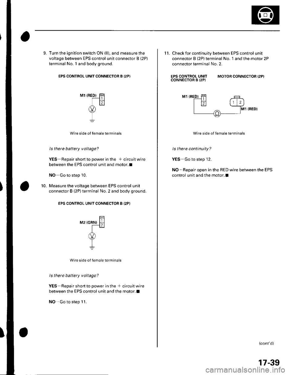
9. Turn the ignition switch ON (ll), and measure the
voltage between EPS control unit connector B (2P)
terminal No. I and body ground.
EPS CONTROL UNIT CONNECTOR B (2PI
M1 {RED} HT-----l | |lil
(v)
I
I
Wire side o{ Iemale terminals
ls there battety voltage?
YES-Repair short to power in the + circuit wire
between the EPS control unit and motor.l
NO Go to step 10.
Measure the voltage between EPS control unit
connector B {2P}terminal No. 2 and body ground.
EPS CONTROL UNIT CONNECTOR B (2P}
mz rcnrur ll-l
A(v)
YI
Wire side of female terminals
ls there battery voltage?
YES Repair short to power in the + circuitwire
between the EPS control unit and the motor.a
NO- Go to step 1 1.
10.
11. Check for continuity between EPS control unit
connector B (2P) terminal No. 1 and the motor 2P
connector terminal No. 2.
EPS CONTROL UNITCONNECTOR B 12P)MOTOR CONNECTOR {2PI
M1 IRED)
M1 (RED}
Wire side of female terminals
ls there continuity?
YES-Go to step '12.
NO-Repair open in the RED wire between the EPS
control unit and the motor.l
(cont'd)
17-39
Page 638 of 1139
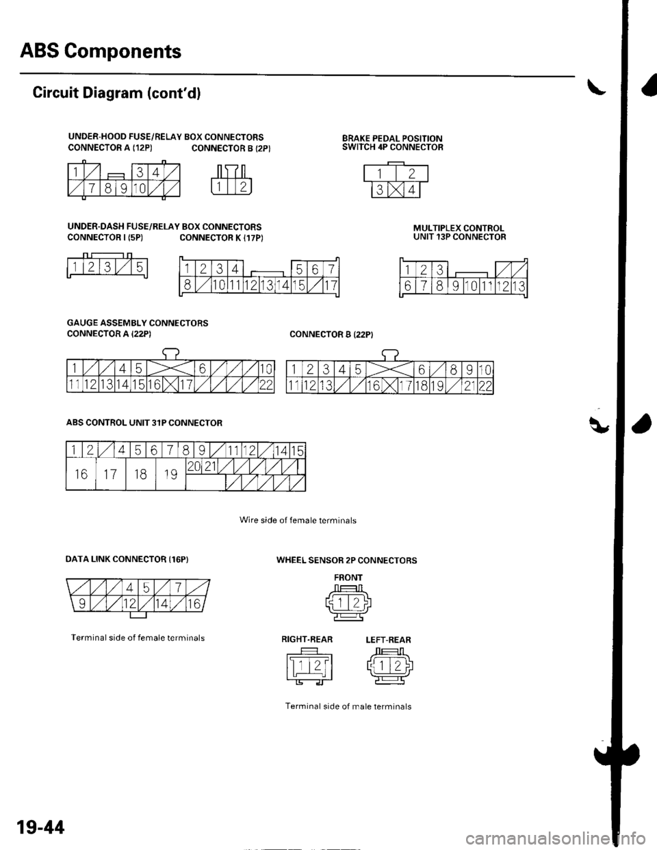
ABS Components
q,
CONNECTOR A {12P)BRAKE PEDAL POSITIONSWITCH 4P CONNECTOR
Circuit Diagram (cont'd)
UNDER-HOOD FUSE/RELAY BOX CONNECTORSCONNECTOR A {12P) CONNECTOR B {2P}
UNDER.DASH FUSE/RELAY BOX CONNECTORSCONNECTOR I {5P)CONNECTOR K I17P)MULTIPLEX CONTROLUNIT 13P CONNECTOR
CONNECTOR B I22PI
1l2l3l,/15
GAUGE ASSEMBLY CONNECTORS
CONNECTOR A I22P)
WHEEL SENSOR 2P CONNECTORS
FRONT
J --T:-l Ltqtt/)l'l L_.:-:J r\-r-----Tr'e:l
RIGHT.REAR LEFT-REAR
tslTt?t /J 1T-1\I tL | rlziJ
Terminal side of male lerminals
ABS CONTROL UNIT 3IP CONNECTOR
OATA LINK CONNECTOR {16P)
Terminal side of female terminals
Wire side of female terminals
1234567
810111213141511
123,/ ,/
67891011n213
1245678I11121415
161118192021/1,/1,/vl,/l
/t,/t/t,/t/
19-44
Page 804 of 1139
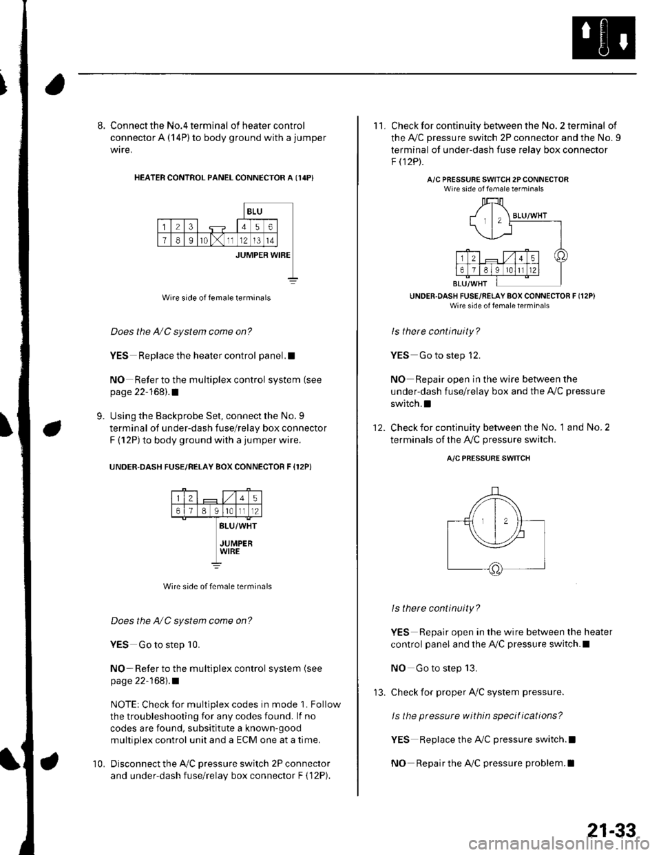
8. Connect the No.4 terminal ofheatercontrol
connector A (14P) to body ground with a jumper
wire,
HEATER CONTROL PANEL CONNECTOR A I14P}
BLU
23456
78Ir0lx1112l3t4
JUMPER WIBE
Wire side of female terminals
Does the A/C system come on?
YES Replace the heater control panel.!
NO Refer to the multiplex control system (see
page 22-168).1
Using the Backprobe Set, connect the No. 9
terminal of under-dash fuse/relay box connector
F (12P) to body ground with a jumper wire.
UNOER.DASH FUSE/RELAY BOX CONNECTOR F {12P}
9.
25
61B g lrotll2
BLU/WHT
JUMPERWIRE
Wire side of female terminals
Does the NC system come on?
YES Go to step 10.
NO- Refer to the multiplex control system (see
page 22-168).1
NOTE: Check for multiplex codes in mode '1. Follow
the troubleshooting {or any codes found. lf no
codes are found, subsititute a known-9ood
multiplex control unit and a ECM one at a time.
Disconnect the Ay'C pressure switch 2P connector
and under-dash fuse/relay box connector F { 12P).
10.
'13.
21-33
11. Check for continuity between the No. 2 terminal of
the A,/C pressure switch 2P connector and the No. 9
terminal of under-dash fuse relav box connector
F t12Pt.
A/C PRESSURE SWITCH 2PCONNECTORWire side of female terminals
UNDER.OASH FUSE/RELAY BOX CONNECTOR F (12P)
Wire side of fenale lerrrinal'
ls there continuity?
YES Go to step 12.
NO Repair open in the wire between the
under-dash fuse/relay box and the A,,/C pressure
switch.I
Check for continuity between the No. 1 and No. 2
terminals of the A,/C pressure switch.
12.
A/C PRESSURE SWITCH
ls there continuity?
YES Repair open in the wire between the heater
control panel and the A,/C pressure switch.l
NO Go to step 13.
check for proper Ay'C system pressure.
ls the pressure within specitications?
YES Replace the AilC pressure switch.l
NO Repair the AilC pressure problem.I
Page 986 of 1139
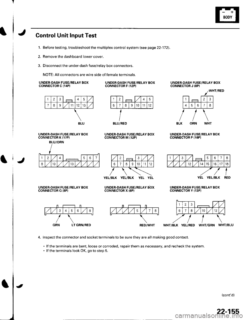
Control Unit Input Test
1. Before testing, trou bleshoot the m u ltiplex contro I system (see page 22-172).
2, Remove the dashboard lower cover.
3. Disconnect the under-dash fuse/relay box connectors.
NOTE: All connectors are wire side of female terminals.
UNDER.DASH FUSE/RELAY BOXCONNECTOR C {1itPlUNDER.DASH FUSE/RELAY BOXCONNECTOR F I12P)
UNDER.DASH FUSE/RELAY BOXCONNECTOR M Il2PI
UNDER-OASH FUSE/RELAY BOXCONNECTOR J {8PI
UNDER.OASH FUSE/RELAY BOXCONNECTOR P I18PIUNDER.DASH FUSE/RELAY BOXCONNECTOR K {17PI
BLU/ORN
UNDER.DASH FUSE/RELAY BOXCONNECTOR O (8P)
YEL/BLK YEL/BLK YEL YEL
UNDER-DAsH FUsE/neLeY sbxCONNECTOR X (8P)
YEL YEL/BLK
UNDER.DASH FUSE/RELAY BOXCONNECTOR Y {13P)
,/1,/34568
LT GRN/REDWHT/BLK YEL/RED WHT/GRN WHT/BLU
4. Inspect the connector and socket terminals to be sure they are all making good contact.
. lf the terminals are bent, loose orcorroded, repairthem as necessary, and recheckthe system.. lf the terminals look OK, go to step 5.
(cont'd)
GRN
BLU/REDBLU
RED/WHT
22-155
Page 1006 of 1139
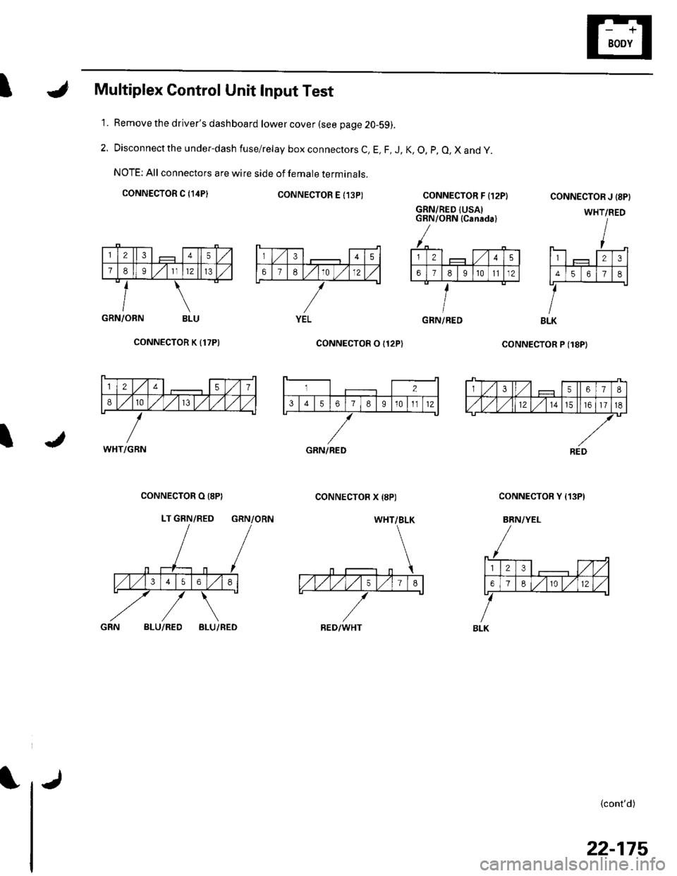
IMultiplex Control Unit Input Test
Remove the driver's dashboard lower cover (see page 20-59).
Disconnect the under-dash fuse/relay box connectors C, E, F, J, K, O, p, O, X and y.
NOTE: All connectors are wire side of female terminals.
CONNECTOR C {14P}CONNECTOR E I13P)
1.
2.
CONNECTOR F {12P}
GRN/RED {USAIGRN/ORN (Canada)
coNNECTOR P (18P)
CONNECTOR J {8PI
WHT/RED
123
4561
BLK
{cont'd)
GRN/ORN BLU
CONNECTOR K {17P)
I
CONNECTOR O I12P)
CONNECTOR X {8P)CONNECTOR O (8P}
LT GRN/RED GRN/ORN
CONNECTOR Y {13P)
BRN/YEL
BLU/REDBLU/RED
345
67E10 )./12
YELGRN/RED
12457
810/V,/ l,/
WHT/GBN
3567I
,/1,/l,/121517
REDGRN/RED
WHT/BLK
RED/WHT
23,/1,/
618r012
BLK
22-175