ESP HONDA CIVIC 2002 7.G Workshop Manual
[x] Cancel search | Manufacturer: HONDA, Model Year: 2002, Model line: CIVIC, Model: HONDA CIVIC 2002 7.GPages: 1139, PDF Size: 28.19 MB
Page 2 of 1139
INTRODUCTION
Safety
Your safety, and the satety of others, is very important. To helpyou make informed decisions, we have provided safetymessages, and other safety information throughout this manual.Of course, it is not practical or possible to warn you about all thehazards associated with servicing this vehicle. You must useyour own good judgment.
You will find impoftant safety information in a variety of formsincluding:. Satety Labels - on the vehicle.. Satetv Messages preceded by a salety alert symbol A andone of three signal words, DANGEF, WARNING, or CAUTION.These signal words mean:
tmEnEEril y;,: H,ll i": 5* i5"?;r s E R I o u s LY H u Br ir
E$EEEE ys,: f#,ff ,:hl:3,:JjERrousLY HURT ir
tlGtltT]llilll You cAN b€ HUBT if vou don't follow
. lnstructions - how to service this vehicle correctlv and safelv.
All information contained in this manual is based on the latestproduct information available at the time of printing. We reservethe right to make changes at any time without notice. No part ofthis Oublication maV be reDrodLrced, or stored in a retrievalsystem, or transmitted, in any form by any means, electronic,mechanical, photocopying, recording, or otherwise, without theprior written permission o{ the publisher. This includes text,figures, and tables-
As vou read this manual, vou will tind information that ispreceded by a @ symbol. The purpose of this message isto help prevent damage to your vehicle, other property, or theenvironment,
*Bodyz-tl!^t l
First Edition 8/2002 1,168 pages HONDA MOTOR CO.. LTD.All Rights Reserved Service Publication OfficeSpecifications apply to U.S.A. and Canada
As seclion3 with *inclode SRS comoonentsispecial precautionsare required when servicing.
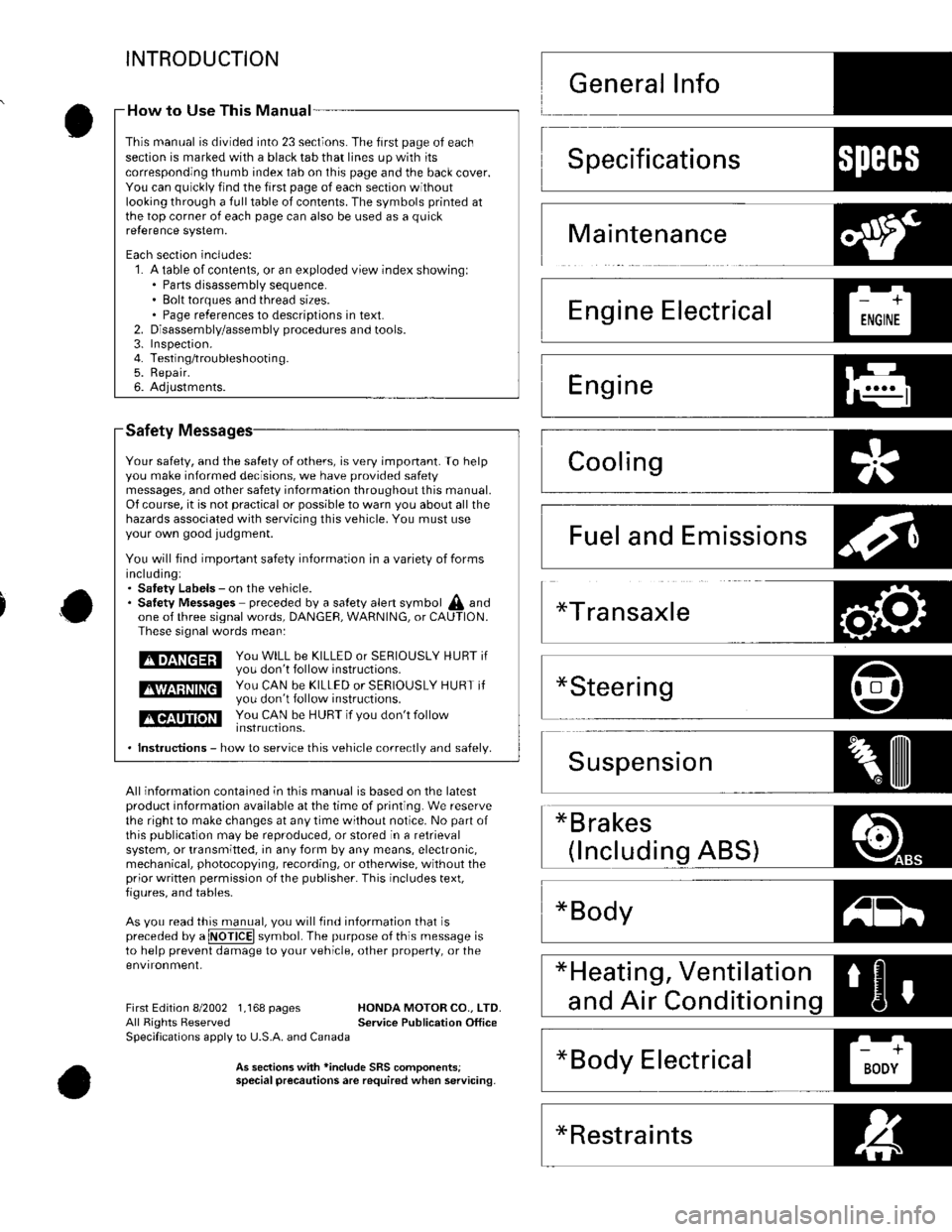
How to Use This Manual -
This manual is divided into 23 sections. The first page of eachseclion is marked with a black tab that lines up with itscorresponding thumb index tab on this page and the back cover.You can quickly find the first page of each section withoutlooking through a full table of contents. The symbols printed atthe top corner of each page can also be used as a quickre{erence system.
Each section includes:1. A table of contents, or an exploded view index showingl. Parts disassembly sequence.. Bolt torques and thread sizes.. Page references to descriptions in text.Disassembly/assembly procedures and tools.Inspefiron.Testing/troubleshootin g.Repair.Adjustments.
2.3.4.5.6.
Specifications1)ll:{l+'
Maintenance
Emissions
*Restraints
Page 22 of 1139
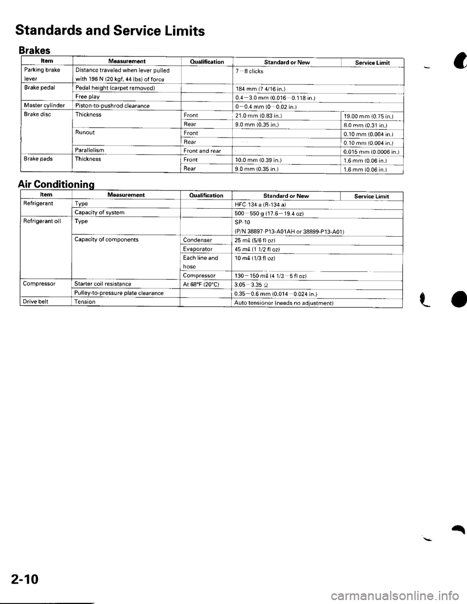
ItemM€asurementOualificationStandard or NewService LimitParking brake
lever
Distance traveled when lever pulled
with 196 N (20 kgf, 44 lbs) ol force
7 8 clicks
Brake pedalPedal height (carpet removed)184 mm (7 4/16 in.)
Free play0.4 3.0 mm (0 016 0 '118 in.)Master cylinderPiston-to-pushrod clearance0 0.4 mm (0 0.02 in.)Erake discThicknessFront21.0 mm (0.83 in.)19.00 mm (0.75 in.)
Rear9.0 mm {0.35 in.)8-0 mm (0.31 in.iRunoutFront0.10 mm (0.004 in.)
Rear0.10 mm (0.004 in.)ParallelismFront and rear0.015 mm (0.0006 in.)Brake padsThicknessFront10.0 mm (0.39 in.)1.6 mm (0.06 in.)
llear9.0 mm {0.35 in.)1.6 mm (0.06 in.)
Standards and Service Limits
Brakes
a
e-o
Air Gonditionin
ItemMoasurementOualilicationStandard or New Service LimitRefrige.antTvpeHFC 134 a (B-134 a)
Capacity of system500 550 g 117.6 19.4 oz)Refrigerant oilTypeSP 1O
(P/N 38897-P13-A01AH or 38899-P13-A01 )Capacity ofcomponentsCondenser25 m0, 15/6 fl ozl
Evaporator45 mA 11 1/2 fl ozt
Each line and
hose
10 m0 (1/3 fl or)
Compressor130 150 m014 1/3 5floz)CompressorStarter coil resistanceAt 68"F (20"C)3.05 3.35 0Pulley-to-pressure plate clearance0.35 0.6 mm (0.014 0.024 in.)Drive beltAuto tensioner lneeds no adjustment)
2-10
q
Page 24 of 1139
cont'
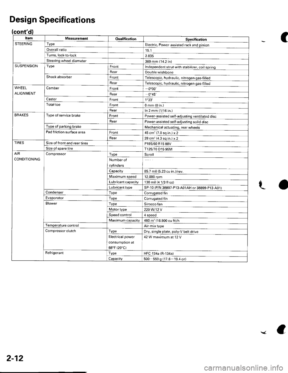
ItemMeasuremeniOualificationSpecilicationSTEERINGTypeElectric, Power assisted rack and pinion
Overall ratio15.1Turns,lock to-lock
Steering wheel diameter360 mm (14.2 in)SUSPENSIONTypeIndependent srrul with stabiliTer. coil springRearDouble wishboneShock absorberFrontTelescopic, hydraulic. nitrogen gas-frlled
RearTelescopic, hydraulic, nitrogen gas,filledWHEEL
ALIGNMENT
CamberFront0"00'
Bear0.45'�
CasterFront1'33'�TotaltoeFront0 mm (0 in.)
RearIn 2 mm (1/16 in.)BRAKESType of service brakeFrontPowerassisted self-adjusling ventilated disc
BearPower-assisted self-adjusting solid discType of parking brakeMechanical actuating, rear wheelsPad friction surface areaFront45 cm'(7.0 sq in.)x2
Rear28 cm'(4.3 sq in.) x 2TIRESSize offront and reartiresPl95/60 815 88VSize o{ spare tireT125r0 D15 95MAIR
CONDITIONING
CompressorTypeScroll
Number of
cylinders
Capacity85.7 m015.23 cu in.)/rev.
Maximum speed12,000 rpm
Lubricant capacity130 m0 {4 1/3 floz)
LubricanttypeSP-10 (P/N 38897'P13-A01AH or38899-P13 A01)CondenserTypeCorrugated finEvaporatorTvpeCorrugated fin
BlowerTypeSirocco fan
Motor type220 Wl12 V
Speed control4 Speeo
Maximum capacity480 m" 116.900 cu ft)/hTemperature controlAirmixtype
Compressor clutchTvpeDry, single plate, poly-V belt drive
Electricalpower
cons!mptron at
68"F (20.C)
42 W maximum at 12 V
RefrigerantTypeHFC 134a (R-134a)
Capacity500 550 g (17.6 19.4 oz)
Design Specifications
C
aL
2-12
../ a
Page 103 of 1139
Cylinder Head
WEC Rocker Arms Test (cont'dl
'10. Loosen the valve on the regulator, and apply thespecified air pressure.
Specified air pressure:
290 kPa 13.0 kgt/cm', 42 psi)
NOTE: lf the synchronizing piston does not moveafter applying air pressure; move the primary orsecondary rocker arm up and down manually byrotating the crankshaft clockwise.
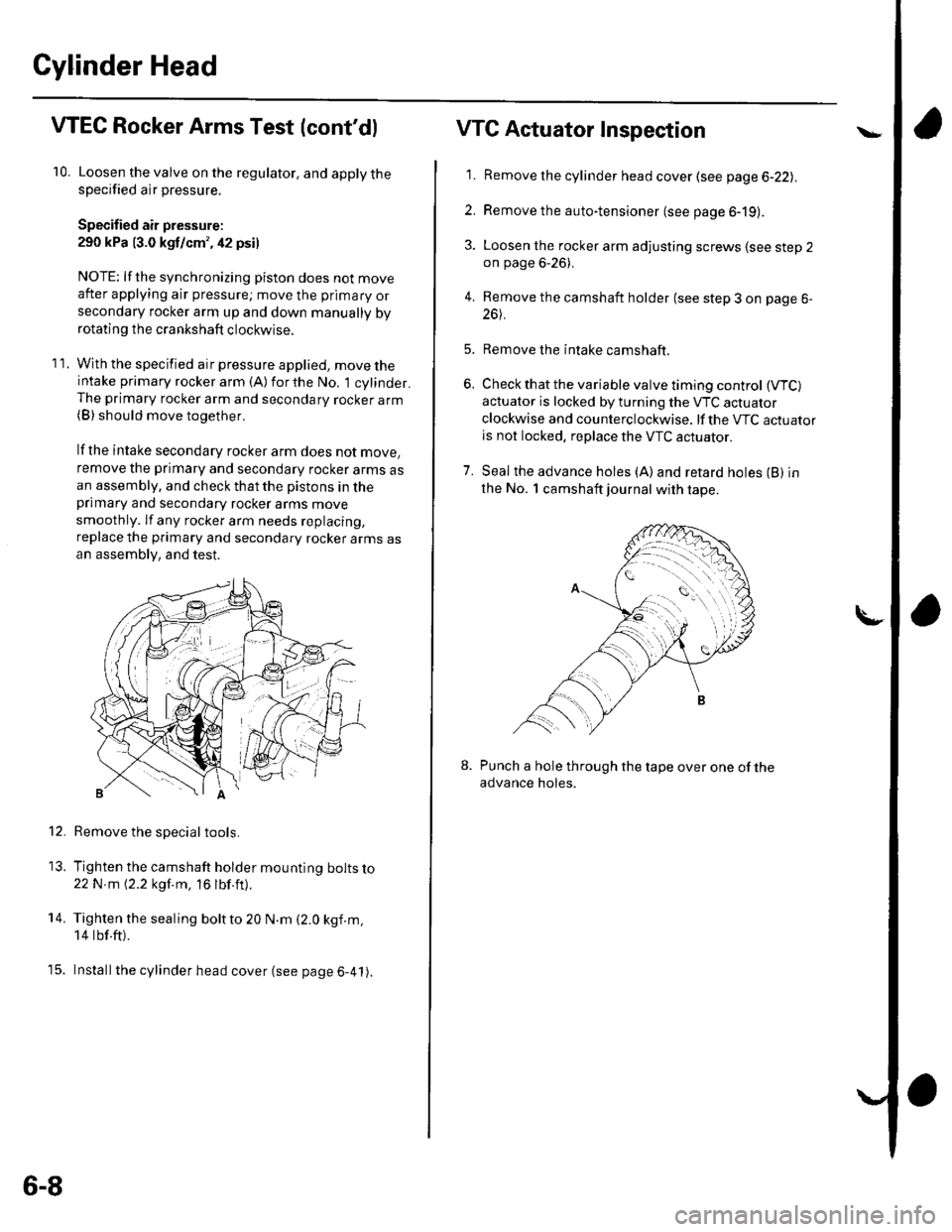
11. With the specified air pressure applied, move theintake primary rocker arm (A)forthe No, 1 cylinder.The primary rocker arm and secondary rocker arm(B) should move together.
lf the intake secondary rocker arm does not move,
remove the primary and secondary rocker arms asan assembly, and check that the pistons in theprimary and secondary rocker arms move
smoothly. lf any rocker arm needs replacing,
replace the primary and secondary rocker arms asan assembly, and test.
Remove the special tools.
Tighten the camshaft holder mounting bolts lo22N m 12.2 kgf.m, 16 lbf.ft).
Tighten the sealing boltto 20 N.m (2.0 kgf.m,
14 tbf.ft).
Installthe cylinder head cover (see page 6-41).
12.
13.
14.
t5.
6-8
VTG Actuator Inspection
'11. Remove the cylinder head cover (see page 6-22lr.
2. Remove the auto-tensioner (see page 6-19).
3. Loosen the rocker arm adjusting screws lsee step 2on page 6-26).
4. Remove the camshaft holder (see step 3 on page 6-
26t.
5. Remove the intake camshaft.
6, Check that the variable valve timing control (VTC)
actuator is locked by turning the VTC actuator
clockwise and counterclockwise. lf the VTC actuatoris not locked, replace the VTC actuator.
7. Seal the advance holes (A)and retard holes (B) in
the No. 1 camshaft journal with tape.
Punch a hole through the tape over one of theadvance holes.
Page 151 of 1139
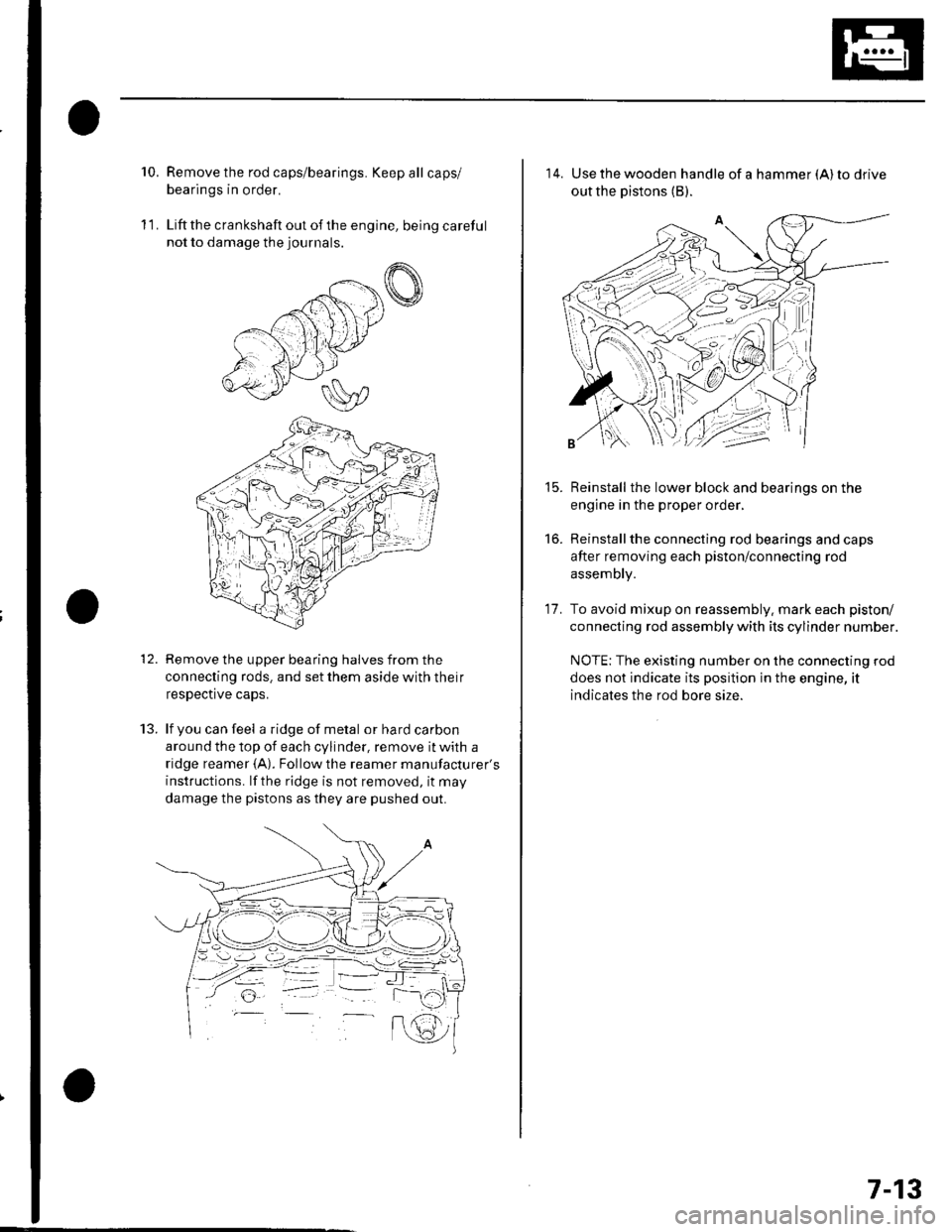
10.Remove the rod caps/bearings. Keep all caps/
bearings in order.
Liftthe crankshaft out ofthe engine, being careful
not to damage the journals.
Remove the upper bearing halves from the
connecting rods. and set them aside with their
respective caps.
lf you can feel a ridge of metal or hard carbon
around the top of each cylinder, remove it with a
ridge reamer {A). Followthe reamer manufacturer's
instructions. lf the ridge is not removed, it may
damage the pistons as they are pushed out.
11.
t.J.
14. Use the wooden handle of a hammer (A) to drive
out the pistons (B).
Reinstall the lower block and bearings on the
engine in the proper order,
Reinstallthe connecting rod bearings and caps
after removing each piston/connecting rod
assembly.
To avoid mixup on reassembly. mark each piston/
connecting rod assembly with its cylinder number.
NOTE: The existing number on the connecting rod
does not indicate its position in the engine, it
indicates the rod bore size.
15.
to.
17.
7-13
Page 215 of 1139
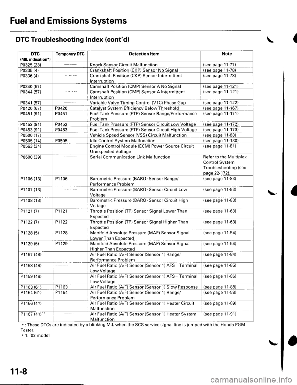
Fuel and Emissions Systems
Knock Sensor Circuit N4alfunction
Crankshaft Position (CKP) Sensor Intermittent(see page 11-78)
(see oaqe 11-121
PO4i{�
TU45I
P0452
Camshaft Position (CMP) Sensor A Intermiftentisee page 11-121)
Yetrgb-le Velye TiTing _controlll/T!) Phqse Gsee oaoe 11-122
CqJalyst System Elficie-ncy Below Thresholdsee oaqe 1 1- 167
Fuel Tank Pressure (FTP) Sensor Range/Performance (seepagell 171)
Sensor Circuit Low V11-172
Fuel Tank Pressure (FTP) Sensor Circuit High V
Vehicle SDeed SensorCircuit Malf unction
Camshaft Position (CMP) Sensor A No
P0451 (91)
see Daqe 11-130)
(see page 1 1-81)
Refer to the l\4ultiplex
Control System
Troubleshooting {see
(see page 1 1-83)
(see paSe 1 1'83)
Barometric Pressure (BARO) Sensor Circuit High{see page 11-83)
P't 121
Pl122
P11f,.8
Throttle Position {TPi Sensor Signal Lower Than(see page 11-63)
-tsee page I r-oJ,
G;tp"s" 1 154)
(*" paSe 1 154)
P1122 ll J
ij1128 (5)
Throttle Position (TP) Sensor Signal Higher Than
Mani{old Absolute Pressure (l\,4AP} Sensor Signal
Loqer Tha n Expected
Manifold Absolute Preisure (MAP) SeiiioiSgnul
Hiqher Than Ex(see page 11-84)
Engine Control Module (ECN4) Power Source Circuil
Serial Communication Link Malfunction
P1106 (13)
P110? (13
P1 108 (ts'
Barometric Pressure (BARO) Sensor Range/
Performance Problem
Barometric Pressure (BARO) Sensor Circuit Low
P1121 11)
P1 129 (5)
P1157 (48)
Pr 158 (48)
Air Fuel Ratio (AVF) Sensor (Sensor 1) Range/
Rerformance Problem
AirFuel Ratio{A"F) Sensor {Sensor 1)AFS Terminal(see page 1 1-85)
Air Fuel Ratio 1AVF) Sensor isensor 'l) AFS + Terminal(see page 1 1-86)
Air Fuel Ratio {A,/F) Sensor {Sensor I ) Slow Response
Air Fuel Ratio (A/F) Sensor (Sensor 1) Range/(see page 1 1-88)
Air Fuel Ratio (4,/F) Sensor (Sensor 1) Heater Circuit
Malfunction
(see page 11-89)
Air Fuel Ratio (A,/F) Sensor (Sensor 1) Heater System
Malfunction
(see page 11-91)
P1 159 (48)
P1163 (61
P1164 (61)
P1 166 (41)
P1 167 (41) '
DTC Troubleshooting Index (cont'd)
" :These DTCS are indicated by a blinking MIL when the SCS servlce signal line is jumped with the Honda PGM
Tester.* 1r '02 model
\
l\."
11-8
\.
(
a
Page 227 of 1139
![HONDA CIVIC 2002 7.G Workshop Manual Fuel and Emissions Systems
System Descriptions {contd)
ECM Inputs and Outputs at Connector A (31P)
\. il
Wire side of female terminals
\.
1AFS]TC2
GP2
3IGPl4PG25PG.16AFS+1
CKP
IKS
10SG211sG1
12IACV
HONDA CIVIC 2002 7.G Workshop Manual Fuel and Emissions Systems
System Descriptions {contd)
ECM Inputs and Outputs at Connector A (31P)
\. il
Wire side of female terminals
\.
1AFS]TC2
GP2
3IGPl4PG25PG.16AFS+1
CKP
IKS
10SG211sG1
12IACV](/img/13/5744/w960_5744-226.png)
Fuel and Emissions Systems
System Descriptions {cont'd)
ECM Inputs and Outputs at Connector A (31P)
\. il
Wire side of female terminals
\.
1AFS]TC2
GP2
3IGPl4PG25PG.16AFS+1
CKP
IKS
10SG211sG1
12IACV
'15
TPS16AFS_18
VSS
19IVAP20vcc221vccl
22AFSHTC+
23LG225
Ct\.4PA
26CMPB(rDc)
27IGPLS428IGPLS329IGPLS230IGPLS,I
NOTE: Standard battery voltage is 12 V.
JorminalnumberWirecolor[€rminal namoDescriptionSignal
19GRN/REDMAP (MANIFOLDABSOLUTE PRESSURESENSOR)
Detects MAP sensor signalWith ignition switch ON (ll):about3 VAt idle: about 1.0 V (depending on enginespeed)
20YEUBLUVCC2 (SENSOR VOLTAGE)Provides sensor voltageWith ignition switch ON {ll): about 5 VWith ionition switch OFF: about0V21YEUREDVCC] (SENSOB VOLTAGE)Provides sensor voltageWith ignition switch ON {ll): about 5 VWith ionition switch OFF: about0V22AFSHTC - (AIR FUELRATIO (A"iFiSENSORHEATER CONTROL + SIDE)
Detects a,/F sensor heatervoltageWith ign;tion switch ON lll): banery voltage
23BRN?ryE LLG2 (LOGIC GROUNDround for the ECM circuLessthan 1.0 V at alltimes24BRN?ryE L1(Lround for the ECM circuLess than '1.0 V at alltimes25B LU,^/VHTCMP A (CAMSHAFT
POSITION SENSOR A)Detects CMP sensor AstonalWith engine running: pulses
26GRNCMP B CAMSHAFTPOSITION (CMP)SENSOBB (TDC (TOP DEAD CENTERSENSORi)
Detects CMP sensor 8 (TDc
sensor)With engine running: pulses
27BRNIGPLS4 {No. 4IGNITIONCOIL PULSE)Drives No, 4 ignition coiWith ignition switch ON (ll)r about 0 vWith engine running: pulses28WHT/BLUIGPLS3 {No.3IGNITIONCOIL PULSE)Orives No.3 rgnition coi
29BLU/REDlGPLS2lNo.2 IGNITIONCOIL PTJLSE)Drives No.2 ignition coil
30YEUGRNIGPLSI (No. 1 IGNITIONco
PlltsF)Drives No. I ignition coil
11-20
\.
a
a
Page 237 of 1139
Fuel and Emissions Systems
(System Descriptions (cont'dl
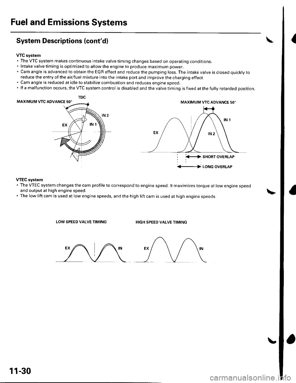
VTC system. The VTC system makes continuous intake valve timing changes based on operating conditions.. Intake valve timing is optimized to allow the engine to produce maximum power.'CamangleisadvancedtoobtaintheEGReffectandreducethepumpingloss.Theintakevalveisclosedquicklyto
reduce the entry of the airlfuel mixture into the intake port and improve the charging effect.. Cam angle is reduced at idle to stabilize combustion and reduces engine speed.'lfamalfunctionoccurs,theVTCsystemcontrol is disabled and the valve timing is fixed at the fully retarded position.
MAXIMUM VTC ADVANCE 50'
i l(-4 sHoRT oVERLAP
'+-|l LoNG oVERLAP
VTEC system' The VTEC system changes the cam profile to correspond to engine speed. lt maximizes torque at low engine speedand output at high engine speed.. The low lift cam is used at low engine speeds, and the high lift cam is used at high engine speeds.
LOW SPEED VALVE TIMINGHIGH SPEED VALVE TIMING
TDC
MAXIMUM VTC ADVANCE 50'
11-30
Page 239 of 1139
Fuel and Emissions Systems
(
{
System Descriptions (cont'd)
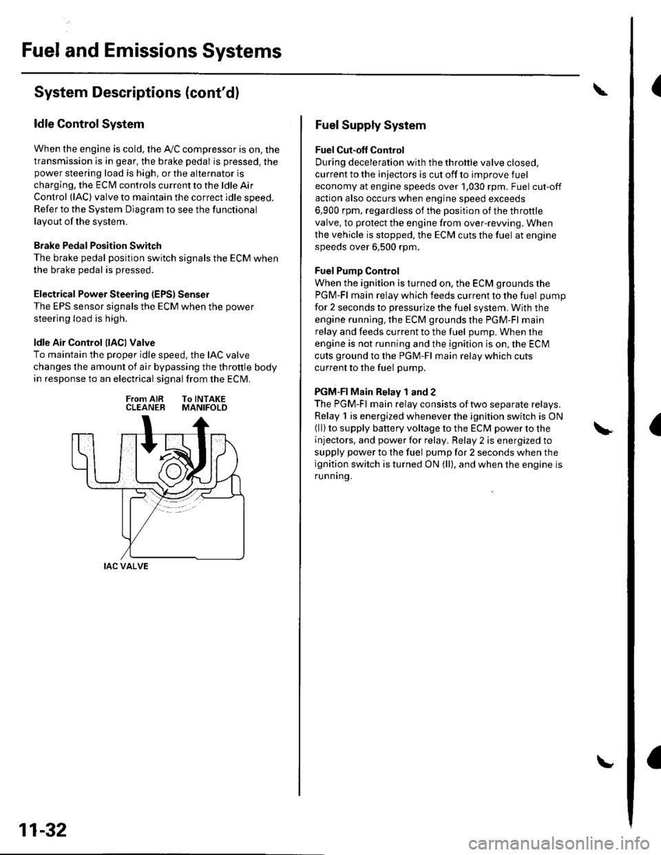
ldle Control System
When the engine is cold, the Ay'C compressor is on, the
transmission is in gear, the brake pedal is pressed. thepower steering load is high, or the alternator is
charging, the ECIM controls current to the ldle Air
Control (lAC) valve to maintain the correct idle speed.
Refer to the System Diagram to see the functional
layout of the system.
Brake Pedal Position Switch
The brake pedal position switch signals the ECM when
the brake pedal is oressed.
Electrical Power Steering (EPS) Senser
The EPS sensor signals the ECM when the power
steering load is high.
ldle Air Control llACl Valve
To maintain the proper idle speed, the IAC valve
changes the amount of air bypassing the throttle body
in response to an electrical signal from the ECM.
From AIR To INTAKECLEANER MANIFOLD
IAC VALVE
11-32
Fuel Supply System
Fuel Cut-off Control
During deceleration with the throttle valve closed,
current to the injectors is cut off to improve fuel
economy at engine speeds over 1,030 rpm. Fuel cut-off
action also occurs when engine speed exceeds
6,900 rpm, regardless of the position of the throttle
valve, to protect the engine from over-rewing. When
the vehicle is stopped. the ECM cuts the fuel at engine
speeds over 6,500 rpm.
Fuel Pump Control
When the ignition is turned on, the ECM grounds the
PGM-Fl main relay which feeds current to the fuel pump
for 2 seconds to pressurize the fuel system, With the
engine running. the ECM grounds the PGM-Fl main
relay and feeds current to the fuel pump. When the
engine is not running and the ignition is on, the ECI\4
cuts ground to the PGM-Fl main relay which cuts
current to the fuel pump.
PGM-FI Main Relay 1 and 2
The PGM-Fl main relay consists of two separate relays.
Relay 1 is energized whenever the ignition switch is ON(ll) to supply battery voltage to the ECM power to the
injectors, and power for relay, Relay 2 is energized to
supply power to the fuel pump for 2 seconds when the
ignition switch is turned ON (ll), and when the engine is
runnrng.
Page 242 of 1139
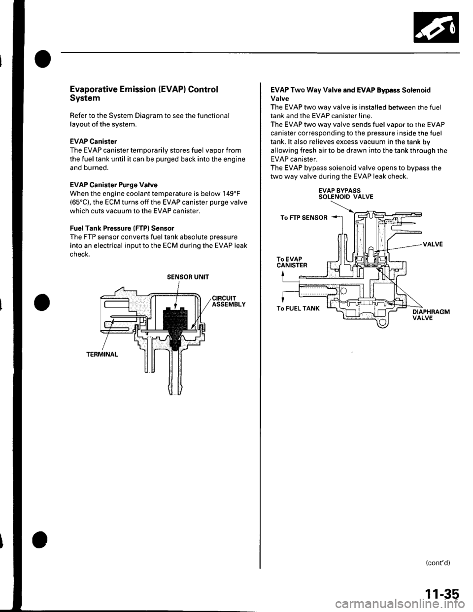
Evaporative Emission (EVAPI Control
System
Refer to the System Diagram to see the functional
layout of the system.
EVAP Canister
The EVAP canister temporarily stores fuel vapor from
the fuel tank until it can be purged back into the engine
and burned.
EVAP Canister Purge Valve
When the engine coolant temperatu re is below 149'F(65'C), the ECM turns off the EVAP canister purge valve
which cuts vacuum to the EVAP canister.
FuelTank Pressure (FTP) Sensor
The FTP sensor converts fueltank absolute pressure
into an electrical inputto the ECM during the EVAP leak
cnecK.
SENSOR UNIT
EVAP Two Way Valve and EVAP Eyp8s Solenoid
Valve
The EVAP two way valve is installed between the fuel
tank and the EVAP canister line.
The EVAP two way valve sends fuel vapor to the EVAP
canister corresponding to the pressure inside the tuel
tank. lt also relieves excess vacuum in the tank by
allowing fresh air to be drawn into the tank through the
EVAP canister.
The EVAP bypass solenoid valve opens to bypass the
two way valve during the EVAP leak check.
EVAP BYPASSSOLENOID VALVE
VALVE
(cont'd)
To FUEL TANK
11-35