ESP HONDA CIVIC 2002 7.G User Guide
[x] Cancel search | Manufacturer: HONDA, Model Year: 2002, Model line: CIVIC, Model: HONDA CIVIC 2002 7.GPages: 1139, PDF Size: 28.19 MB
Page 274 of 1139
8.Check the secondary H02S (Sensor 2) output
voltage with the scan tool,
ls there 1.0 V ot mote?
YES-Go to step 9.
NO Replace the secondary HO2S (Sensor 2).1
Turn the ignition switch OFF.
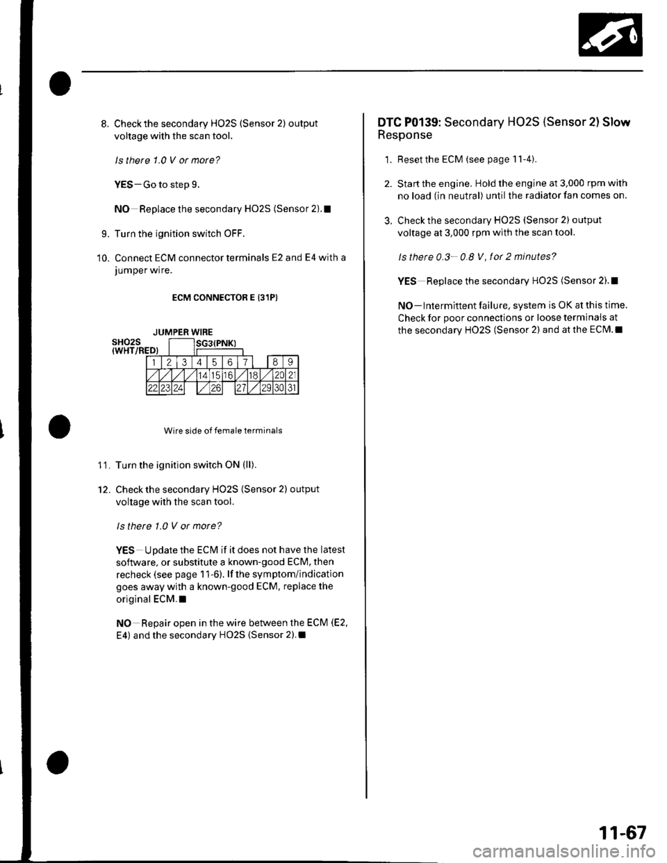
Connect ECM connector terminals E2 and E4 with a
JUmper wrre.
ECM CONNECTOR E 131PI
Wire side of female terminals
Turn the ignition switch ON (ll).
Check the secondary HO2S (Sensor 2) output
voltage with the scan tool.
ls there 1.0 V or more?
YES Update the ECM if it does not have the latest
soflware, or substitute a known-good ECM, then
recheck (see page 1 1-6). lf the symptom/indication
goes away with a known-good ECM. replace the
original ECM.I
NO Repair open in the wire between the ECM (E2,
E4) and the secondary HO2S {Sensor 2).I
9.
10.
11.
12.
JUMPER WIRE
3.
DTC P0139: Secondary HO2S (Sensor 2l Slow
Response
1. Resetthe ECM (see page 11-4).
Start the engine. Hold the engine at 3,000 rpm with
no load (in neutral) until the radiator fan comes on.
Check the secondary HO2S (Sensor 2) output
voltage at 3,000 rpm with the scan tool.
ls thete 0.3- 0.8 V, fot 2 minutes?
YES Replace the secondary HO2S (Sensor 2).!
NO- lntermittent failure, system is OK at this time.
Check for poor connections or loose terminais at
the secondary HO2S (Sensor 2) and at the ECM.I
11-67
Page 295 of 1139
PGM-FI System
DTC Troubleshooting (cont'dl
DTC Pl163: Ay'F Sensor (Sensor 1 ) SlowResponse
NOTE: lf DTC P1162 is stored at the same time as DTC
P1163. troubleshoot DTC P1162 first, then recheckfor
DTC P1163.
1. Reset the ECM (see page 1 1-4).
2. Start the engine. Hold the engine at 3,000 rpm with
no load (in neutral) until the radiator fan comes on.
3. Test-drive under the following conditions:
. 55 mph (89 km/h) steady speed' Transmission in sth gear' Until the Ay'F sensor readiness code or
Temporary DTC Pl163 comes on
4. Check for a Temporary DTC with the scan tool.
ls Temporary DTC P 1163 indicated?
YES Replace the Ay'F sensor (Sensor 1).I
NO Intermittent failu re, system is OK at this time.
Check for poor connections or loose terminals at
the A'lF sensor (Sensor 1 ) and at the ECM. t
11-88
DTC Pl164: A,/F Sensor (Sensor 1) Circuit
Range/Performance Problem
1. Resetthe ECI\4 (see page 1t-4).
2. Start the engine. Holdtheengineat3,000 rpmwith
no load (in neutral) until the radiator fan comes on,
3. Test-drive in 3rd gear. Starting at 1,600 rpm,
accelerate using wide open throttle for at least
5 seconds. Then decelerate for at least 5 seconds
with the throttle completely closed until the A,/F
sensor readiness code is set to complete or
Temporary DTC P1 164 comes on.
4. Check for a Temporary DTC with the scan tool.
ls Temporary DTC P1164 indicated?
YES- Replace the A,,/F sensor (Sensor 1). I
NO Intermittent failure, system is OK at this time.
Check for poor connections or loose terminals at
the Ay'F sensor relay, at the Ay'F sensor (Sensor 1),
and at the EcM.l
Page 409 of 1139
Glutch
Clutch Replacement (cont'dl
Clutch Disc and Pressure Plate Installation
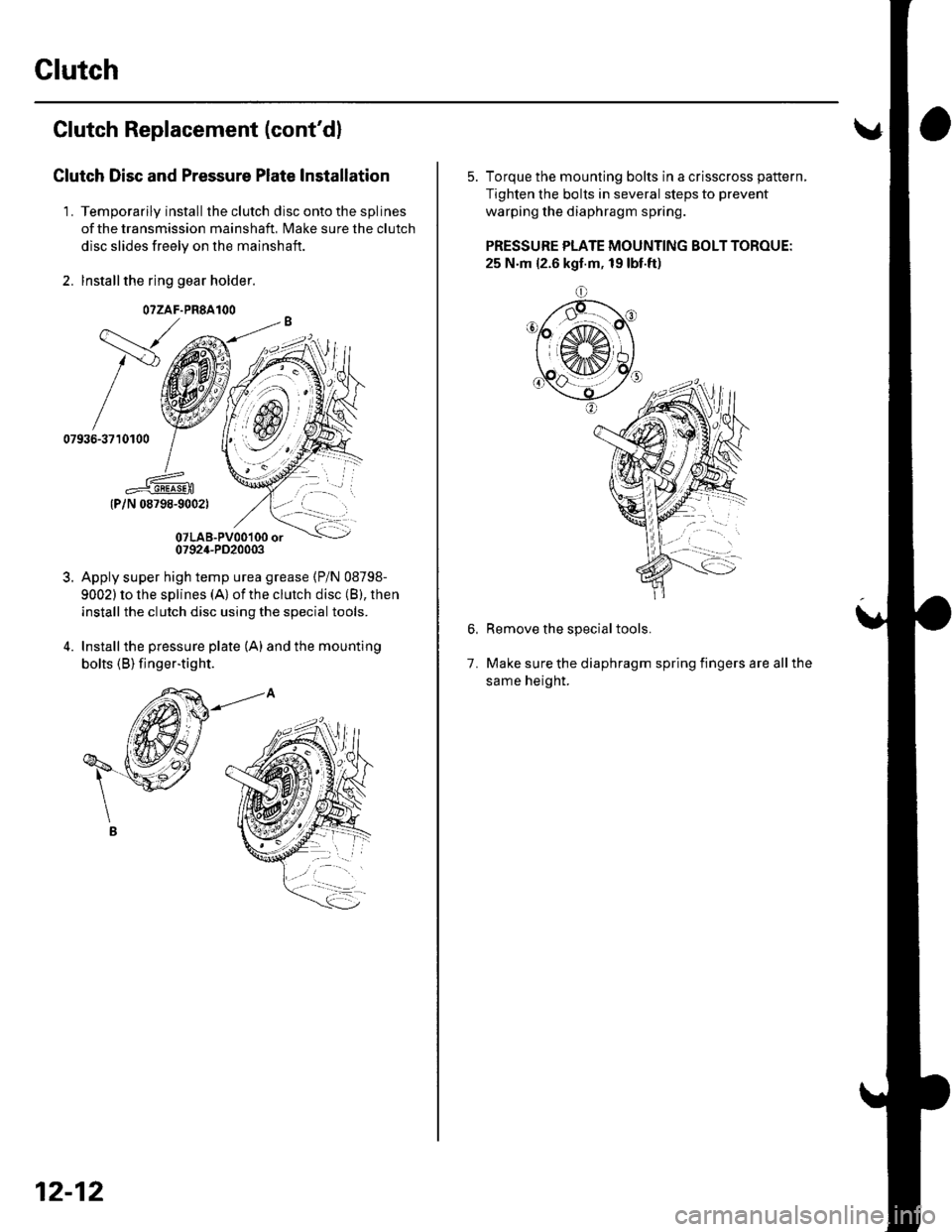
'L Temporarily install theclutch disc ontothesplines
of the transmission mainshaft, Make sure the clutch
disc slides freely on the mainshaft.
2. lnstallthe ring gear holder.
{P/N 08798-9002)
07LAB-PVo0'100 or0792,1-PD20003
Apply super high temp urea grease (P/N 08798-
9002) to lhe splines (A) of the clutch disc (B), then
install the clutch disc using the special tools.
Installthe pressure plate (A) and the mounting
bolts (B) finger-tig ht.
\---,
/v
07936-3710100
3.
O?ZAF.PRSAIOO
12-12
5. Torque the mounting bolts in a crisscross pattern,
Tighten the bolts in several steps to prevent
warping the diaphragm spring.
PRESSURE PLATE MOUNTING BOLT TOROUE:
25 N.m {2.6 kgt.m, 19 lbt.ft)
o
Remove the special tools.
Make sure the diaphragm spring fingers are all the
same height.
1.
Page 576 of 1139
Front Suspension
Stabilizer Link Removal/lnstallation
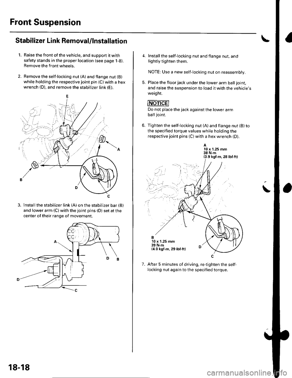
1.Raise the front of the vehicle, and support it with
safety stands in the proper location (see page 1-8).
Remove the front wheels.
Remove the self-locking nut (A) and flange nut {B)while holding the respective joint pin (C) with a hex
wrench (D), and remove the stabilizer link (E).
3. lnstallthe stabilizer link (A) on the stabilizer bar {B)
and lower arm (C) with the joint pins (D) set at the
center of their range of movement.
18-18
4. Install the self-locking nut and flange nut, and
lightly tighten them.
NOTE: Use a new self-locking nut on reassembly.
5. Place the floor jack under the lower arm balljoint,
and raise the suspension to load it with the vehicle's
weaght.
mri-dEl
Do not place the jack against the lower arm
balljoint.
6. Tighten the self-locking nut (A) and flange nut (B) to
the specified torque values while holding the
respective joint pins (C) with a hex wrench (D).
A10 x 1.25 mm38 N.m(3.9 kgf m,28 lbf.ft)
\
..,
1.
B10 x 1.25 mm39 N.m{4.0 kgf.m, 29lbf.ft}
After 5 minutes of driving, re-tighten the self,
locking nut again to the specified torque.
Page 588 of 1139
Rear Suspension
1.
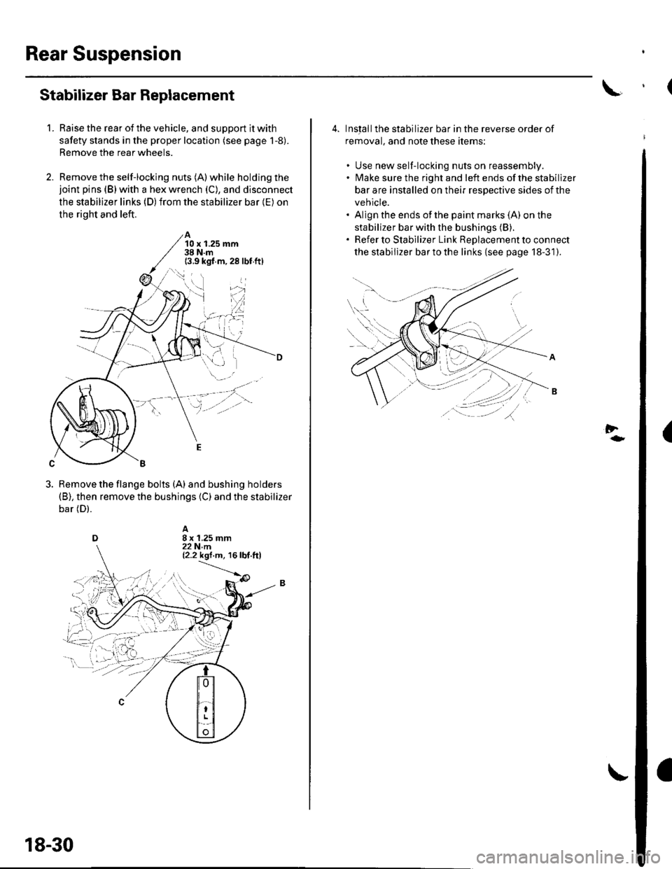
Stabilizer Bar Replacement
Raise the rear of the vehicle, and support it with
safety stands in the proper location (see page 1-8).
Remove the rear wheels.
Remove the self-locking nuts (A) while holding thejoint pins (B) with a hex wrench (C), and disconnect
the stabilizer links (D) from the stabilizer bar {E) on
the right and left.
A10 x 1.25 mm38 N.m(3.9 kgf.m,28 lbf.ft)
Remove the flange bolts (A) and bushing holders(B), then remove the bushings {C) and the stabilizer
bar (D).
18-30
4. Inslallthe stabilizer bar in the reverse order of
removal, and note these items:
. Use new self-locking nuts on reassembly.. lMake sure the right and left ends of the stabilizer
bar are installed on their respective sides of the
vehicle.. Align the ends of the paint marks (A) on the
stabilizer bar with the bushings (B).
. Refer to Stabilizer Link ReDlacement to connect
the stabilizer bar to the links {see page 18-31).
Al\.... '..: .
.----'';-r'--\---r-
-tt'.,'t),
(
Page 589 of 1139
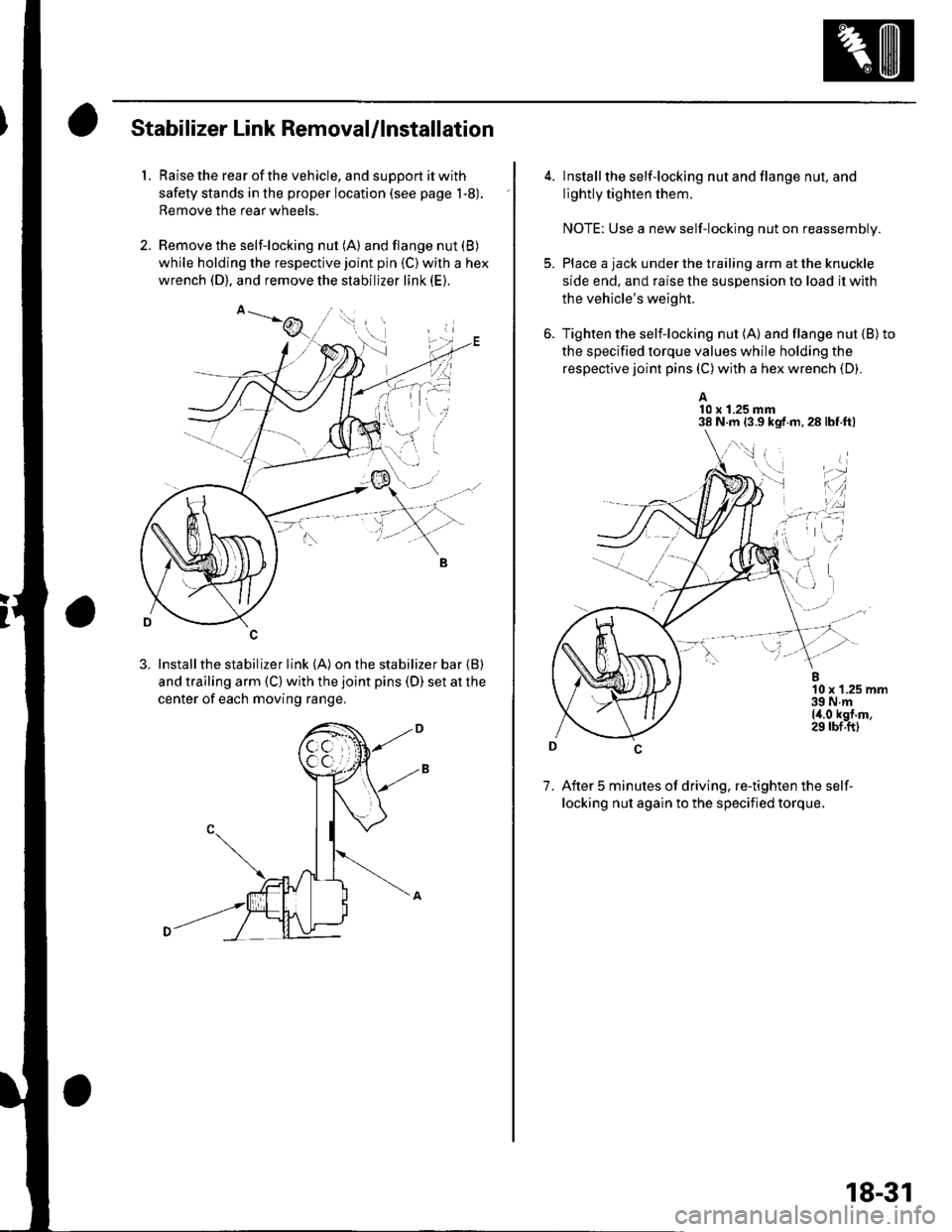
Stabilizer Link Removal/lnstallation
1. Raise the rear of the vehicle, and support it with
safety stands in the proper location (see page 1-8).
Remove the rear wheels.
2. Remove the self-locking nut (A) and flange nut (B)
while holding the respective joint pin {C) wilh a hex
wrench (D), and remove the stabilizer link (E).
3. Installthe stabilizer link (A) on the stabilizer bar {B)
and trailing arm (C) with the joint pins (D) set at the
center of each moving range,
4. lnstall the self-locking nut and flange nut, and
lightly tighten them.
NOTE: Use a new self-locking nut on reassembly.
Place a jack under the trailing arm at the knuckle
side end. and raise the suspension lo load it with
the vehicle's weight.
Tighten the selflocking nut (A) and flange nut {B)to
the specified torque values while holding the
respective joint pins (C) with a hex wrench (D).
A10 x 1.25 mm38 N.m 13.9 kgf.m,28lbf.ftl
7. After 5 minutes of driving, re-tighten the self-
locking nut again to the specified torque.
\,1 i
i'-r d
*l'',:
18-31
Page 611 of 1139
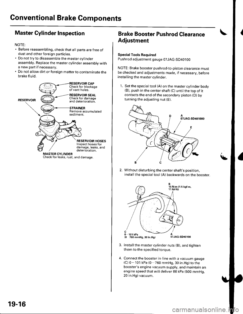
Conventional Brake Components
Master Cylinder Inspection
NOTE:. Before reassembling, check that al I parts are f ree ofdust and other foreign particles.. Do nottryto disassemblethe mastercylinder
assembly. Replace the master cylinder assembly witha new part if necessary.. Do not allow dirt or foreign matter to contaminate thebrake fluid.
RESERVOIB CAPI unecK Ior otocKageof vent holes.
RESERVOIR
,--l RESERvOIR SEALCheck lor damaoe
RESERVOIR HOSESInspect hoses fordamage, leaks, anddeterioration.
r',,.J\+
v
MASTER CYLINDERCheck for leaks, rust, and damage
and deterioration.
STRAINERRemove accumulatedseotment.
19-16
Brake Booster Pushrod Clearance
Adjustment
SpecialTools Required
Pushrod adjustment gauge 07JAG-SD40100
NOTE: Brake booster pushrod-to-piston clearance mustbe checked and adjustments made, if necessarV, beforeinstalling the master cylinder.
1. Setthespecial tool (A) onthe mastercylinder bodv(B), push in the center shaft (C) until the top of itcontacts the end of the secondary piston {D) byturning the adjusting nut (E).
Without disturbing the center shaft's position,
installthe specialtool (A) backwards on the booster.
Install the master cylinder nuts (B), and tighten
them to the specified torque.
Connecl the booster in line with a vacuum gauge
{C) 0-101 kPa {0'-760 mmHg, 30 in.Hg) to thebooster's engine vacuum supply, and maintain anengine speed that will deliver 66 kPa (500 mmHg,20 in.Hg) vacuum.
15 N m {r.511 tbf.ftl
Page 635 of 1139
t
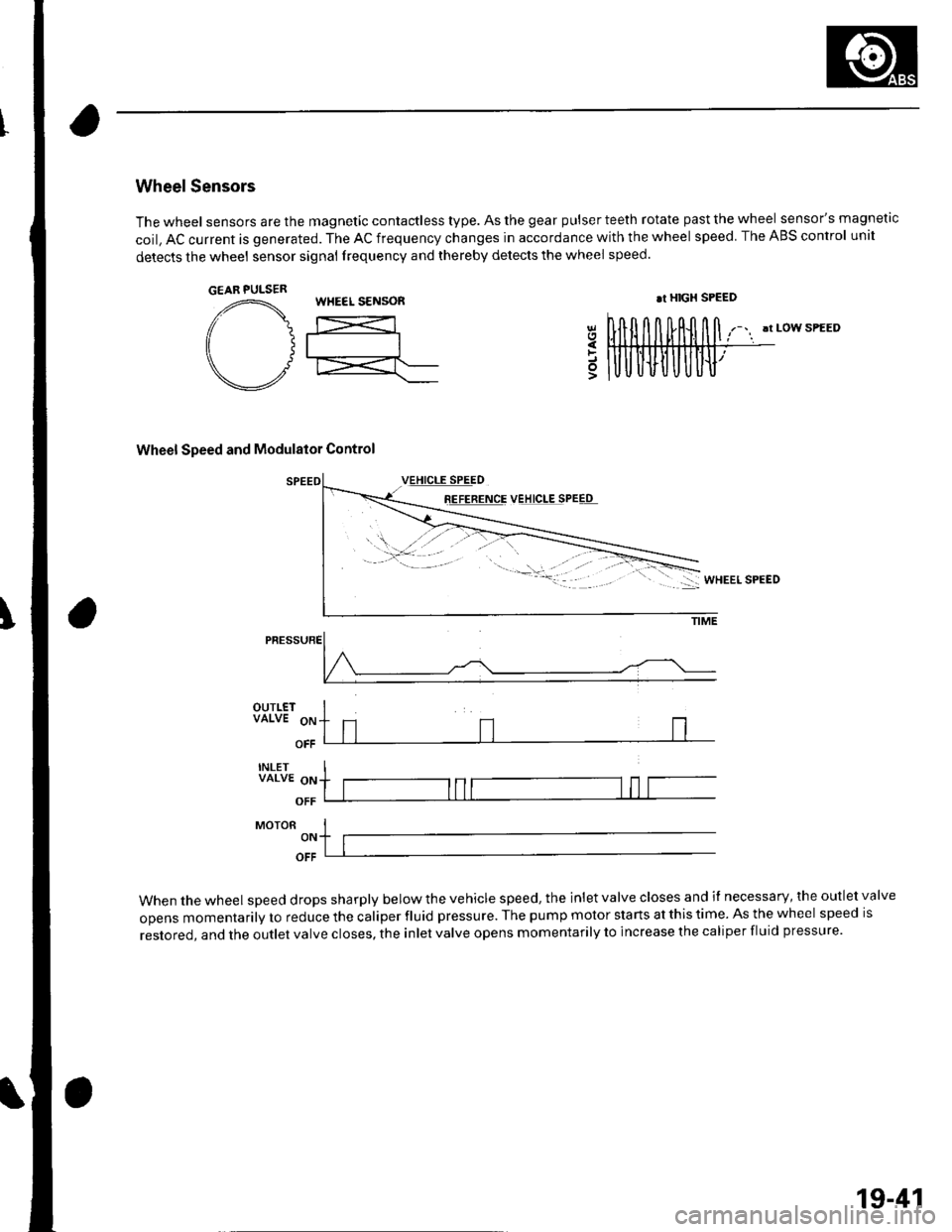
Wheel Sensors
The wheel sensors are the magnetic contactless type. As the gear pulser teeth rotate past the wheel sensor's magnetic
coil, AC current is generated. The AC frequency changes in accordance with the wheel speed. The ABS control unit
detects the wheel sensor signal frequency and thereby detects the wheel speed.
!t LOW SPEED
Wheel Speed and Modulator Control
8E!EEETqE VEJ!q!ESPEEq
5
PRESSURE
OUTLETVALVE 9p
OFF
INLETVALVE oN
OFF
MoroR I-,. ltlOFF
When the wheel speed drops sharply below the vehicle speed, the inlet valve closes and il necessary, the outlet valve
opens momentarily to reduce the caliper fluid pressure. The pump motor starts at this time. As the wheel speed is
restored, and the outlet valve closes, the inlet valve opens momentarily to increase the caliper fluid pressure.
GEAR PULSERWHEEL S€NSOR.r HIGX SPEED
19-41
Page 670 of 1139
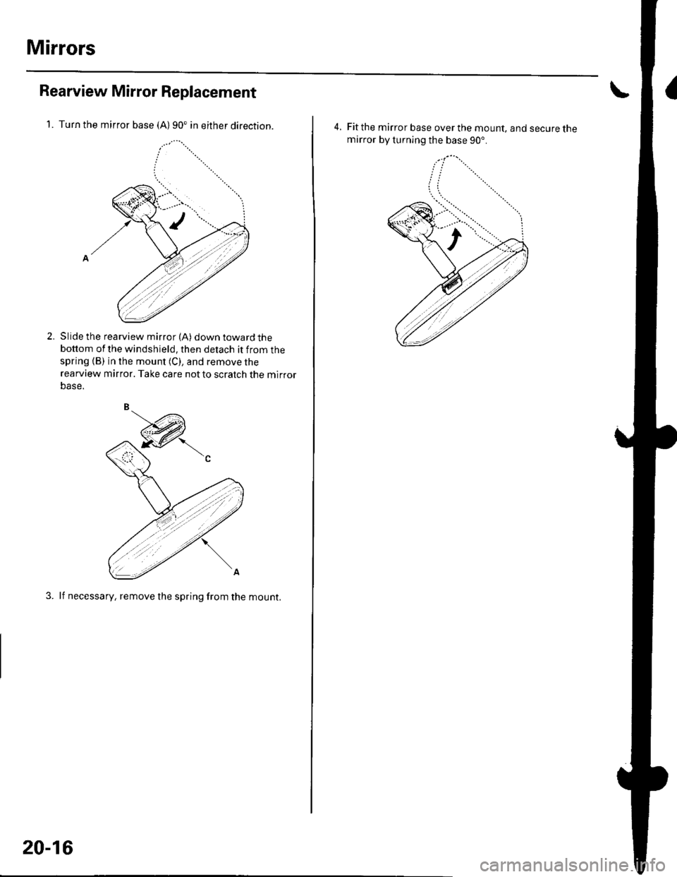
Mirrors
Rearview Mirror Replacement
1. Turn the mirror base (A)90. in either direction.
Slide the rearview mirror (A) down toward thebottom of the windshield, then detach it from thespring (B) in the mount (C), and remove the
rearview mirror. Take care notto scratch the mirror
Dase.
3. lf necessary, remove the spring from the mount.
2.
20-16
4, Fit the mirror base over the mount, and secure themirror by turning the base 90".
Page 740 of 1139

Bumpers
Rear Bumper RemovaUlnstallation
NOTE:' Have an assistant help you when removing and installing the rear bumper.. Take care not to scratch the rear bumper and body.. When prying with a flat-tip screwdriver, wrap it with protective tape to prevent damage.. Put on gloves to protect your hands.
L Remove the rear bumDer as shown.
2. Installthe bumper in the reverse order of removal, and note these items:
. Make sure both rear side marker light connectors are plugged in properly.'Makesuretherearbumperengagesthehooksofthesidespacers,sidebrackets,andupperbracketsonboth
sides securely.. Make sure the upper spacers of the rear bumper engage the clips on the body securely.. Replace any damaged clips.
: Screw, 2
XJ
) : Clip,
?ri)
\sI
Fastener Locations
A>:Bolt,2 B
/h-
\-P-
) : Screw, 2
ffiI"-ut ^*
c>
SIDE BRACKET
UPPER SPACER
UPPER BRACKET
\
SIDE SPACER
:r
'-
A
AD
LEFT REAR SIDE MARKERLIGHT CONNECTOR
,6 x 1.0 mm/ 9.eN.n,/ 11.0 kgl m,./ 1.2tbt.ttl
a
\
CAP
REAR BUMPER
20-86