Master switch HONDA CIVIC 2002 7.G Workshop Manual
[x] Cancel search | Manufacturer: HONDA, Model Year: 2002, Model line: CIVIC, Model: HONDA CIVIC 2002 7.GPages: 1139, PDF Size: 28.19 MB
Page 398 of 1139
Clutch
Special Tools ......... 12-2
Comoonent Location Index .......................,............. 12-3
Clutch Pedal, Clutch Pedal Position Switch, and
Clutch Interlock Switch Adiustment .................... 12-4
Cf utch Master Cylinder Rep|acement ..................... 12-5
Slave Cylinder Replacement .'........ 12-7
Clutch Replacement ................... ..... 12-9
Page 400 of 1139
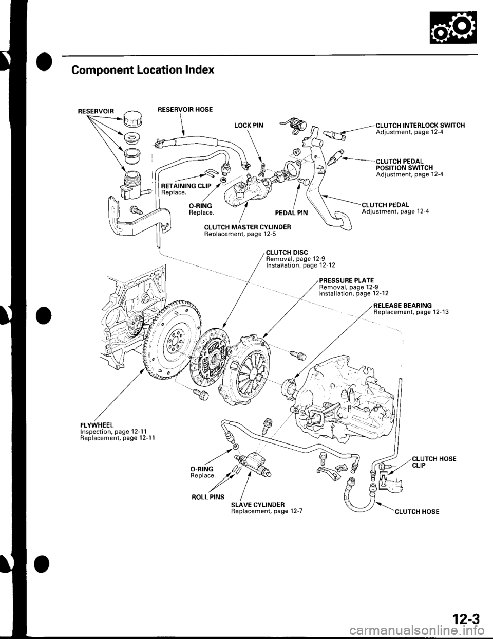
Component Location Index
""*--/\,L_.Ei
/i
(,'.'
CLUTCH INTERLOCK SWITCHAdjustment, page 12-4
CLUTCH PEDALPOSTTTON SWITCHAdjustment, page'12-4
RETAINING CLIPReplace.
_,___-,-s\
O-RINGReplace.UTCH PEDALAdjustment, Page 12 4
CLUTCH MASTER CYLINDERReplacement, page l2-5
CLUTCH DISCBemoval, page 12-9Installation, page'12-12
PRESSURE PLATERemoval, page'12-9lnstallation, page 12-12
FLYWHEELInspection, page'12-1 1Replacement, page 12-1 1
SLAVE CYLINDERReplacement, page 12-7
RELEASE BEARINGBeplacement, page 12-13
\".rr"*"o*
CLUTCH HOSECLIP
12-3
Page 401 of 1139
Clutch
Clutch Pedal, Clutch
Adjustment
NOTE:. To check the clutch pedal position switch(see page 4-45).. To check the clutch interlock switch (see page 4-6).. Remove the driver's side floor mat before adjusting
the clutch pedal.. The clutch is self-adjusting to compensate for wear.. lf there is no clearance betweenthe mastercylinderpiston and push rod, the release bearing will be held
against the diaphragm spring. which can result in
clutch slippage or other clutch problems.
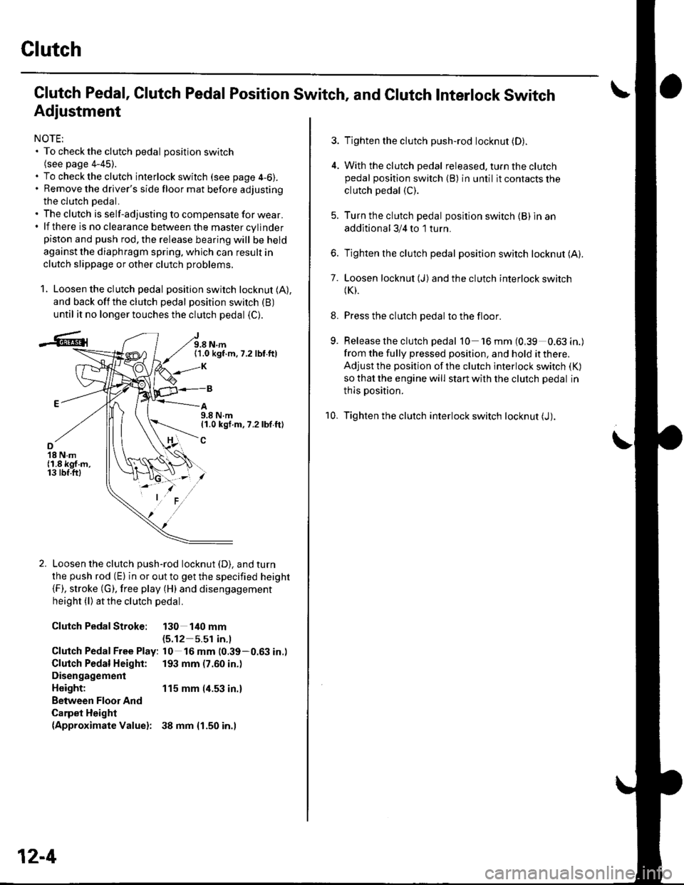
1. Loosen the clutch pedal position switch locknut (A),
and back off the clutch pedal position switch (B)
until it no longer touches the clutch pedal (C).
J9.8 N.m(1.0 kgf.m,7.2 lbf.ft)
A9.8 N.m11.0 kgf.m, 7.2 lbf.ft)
o18 N.m{1.8 kgf.m,13 tbf.ftl
Loosen the clutch push-rod locknut (D). and turn
the push rod (E) in or out to get the specified height(F), stroke (G). free play (H) and disengagement
height (l) atthe clutch pedal.
Clutch PedalStroke: 130 140 mm(5.12 5.51 in.l
Clutch Pedal Free Play: l0 16 mm (0.39-0.63 in.)
Clutch Pedal Height: 193 mm (7.60 in.)
Disengagement
Height: 115 mm (4.53 in.)
Between Floor And
Carpet Height(Approximate Valuel: 38 mm {1.50 in.l
12-4
Pedal Position Switch, and Clutch Interlock Switch
3. Tighten the clutch push-rod locknut (D).
4. With the clutch pedal released. turn the clutchpedal position switch (B) in until it contacts the
clutch pedal (C).
5. Turn the clutch pedal position switch {B) in an
additional 3/4 to 1 turn.
6. Tighten the clutch pedal position switch locknut (A).
7. Loosen locknut (J)and the clutch interlock switch(K).
8. Press the clutch pedal to the floor.
9. Release the clutch pedal 10 'l6mm(0,39 0.63in.)
from the fully pressed position, and hold it there.
Adjust the position of the clutch interlock switch (K)
so that the engine will start with the clutch pedal in
thls position.
10. Tighten the clutch interlock switch locknut (J).
Page 596 of 1139
Brakes
Conventional Brake Components
Special Tools ... ..... ... l9-2
Component Location Index ......................................... 19-3
Brake System Inspection and
Tests ............... .......... 19-4
Brake Pedal and Brake Pedal Position Switch
Adjustment .............. 19-6
Parking Brake Check and
Adjustment .............. 19-7
Brake System Bleeding ...................... 19-8
Brake System Indicator Circuit
Diagram ................... 19-9
Parking Brake Switch Test ................. 19-10
Brake Fluid Level Switch Test ...................................... 19-10
Front Brake Pads lnsoection and
Replacement ........... 19-11
Front Brake Disc Inspection ............... 19-13
Front Brake Calioer Overhaul ...................................... 19-14
Master Cylinder Replacement ........... 19-15
Master Cylinder Inspection ................ 19-16
Brake Booster
Pushrod Clearance Adjustment ................................ 19-16
Brake BoosterTest ................... .......... 19-18
Brake Booster Reolacement .............. 19-19
Rear Brake Pads Inspection and
Reolacement ........... 19-20
Rear Brake Disc Inspection ................ 19-22
Rear Brake Caliper Overhaul ....................................... 19-23
Brake Hoses and Lines Insoection .... 19-24
Brake Hose Reolacement ................... 19-25
Parking Brake Cable Replacement .............................. 19-26
ABS (Anti-lock Brake System)
Gomponents ... 19-29
Page 598 of 1139
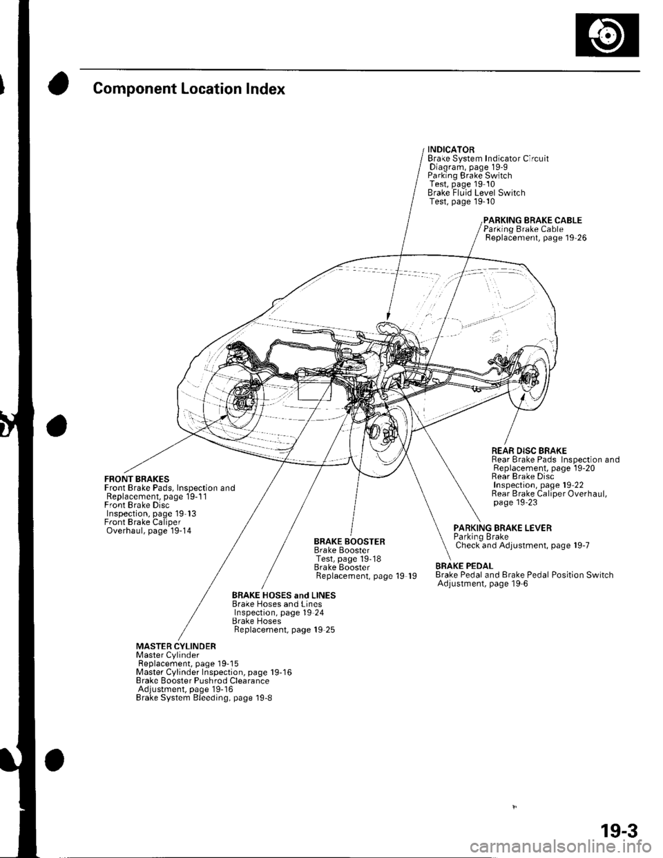
Component Location Index
FRONT BRAKESFront Brake Pads, Inspection andReplacement, page 19-1 1Front Brake DiscInspection, page 19'13Front Brake CaliperOverhaul, page 19-14
INDICATORBrake System Indicator CircuitDiagram, page 19-9Parking Brake SwitchTest, page 19 10Brake Fluid Level SwitchTest, page 19-10
BRAKE CABLE
BRAKE BOOSTERBrake BoosterTest, page 19-18Brake EoosterReplacement, page 19 19
Parking Brake CableReplacement, page 19 26
REAR DISC BRAKERear Brake Pads Inspection andReplacement, page l9-20Rear Brake DiscInspection, page 19'22Rear Brake Caliper Overhaul,page 19'23
PARKING BRAKE LEVERParkino BrakeCheck and Adjustment, page 19-7
BRAKE PEDALBrake Pedal and Erake Pedal Position SwitchAdjustment, page l9-6
BRAKE HOSES and LINESBrake Hoses and LinesInspection, page 19 24Brake HosesReplacement, page 19 25
MASTER CYLINDERMaster CylinderFl6^1.^6m6nr ^2^o 1O-18Master Cylinder Inspection, page 19-16Brake Booster Pushrod ClearanceAdjustment, page'19-16Brake System Bleeding, page 19-8
19-3
Page 600 of 1139
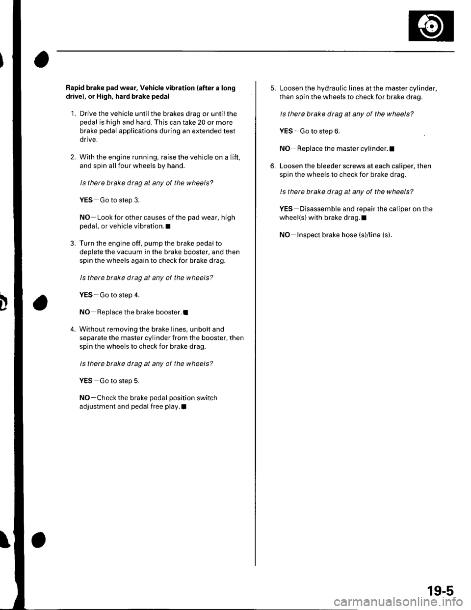
Rapid brake pad wear. Vehicle vibration {after a long
drivel, or High, hard brake pedal
1. Drive the vehicle until the brakes drag or untilthe
pedal is high and hard. This can take 20 or more
brake pedal applications during an extended test
drive.
2. With the engine running, raise the vehicle on a lift,
and spin all four wheels by hand.
ls there btake drag at any of the wheels?
YES Go to step 3.
NO Look for other causes of the pad wear, high
pedal, or vehicle vibration.I
3. Turn the engine off, pump the brake pedal to
deplete the vacuum in the brake booster, and then
spin the wheels again to check for brake drag.
ls therc brake dtag at any ot the wheels?
YES-Go to step 4.
NO Replace the brake booster.I
4. Without removing the brake lines, unbolt and
separate the master cylinder from the booster, then
spin the wheels lo check for brake drag.
ls there btake drag at any of the wheels?
YES Go to step 5,
NO-Check the brake pedal position switch
adjustment and pedal free play.I
5. Loosen the hydraulic lines at the master cylinder,
then spin the wheels to check for brake drag.
ls there brake drag at any of the wheels?
YES Go to step 6.
NO- Replace the master cylinder.l
6. Loosen the bleeder screws at each caliper, then
spin the wheels to check for brake drag.
Is there brake drag at any of the wheels?
YES Disassemble and repair the caliper on the
wheel(s) with brake drag.l
NO Inspect brake hose (s)/line (s).
19-5
Page 613 of 1139
Gonventional Brake Components
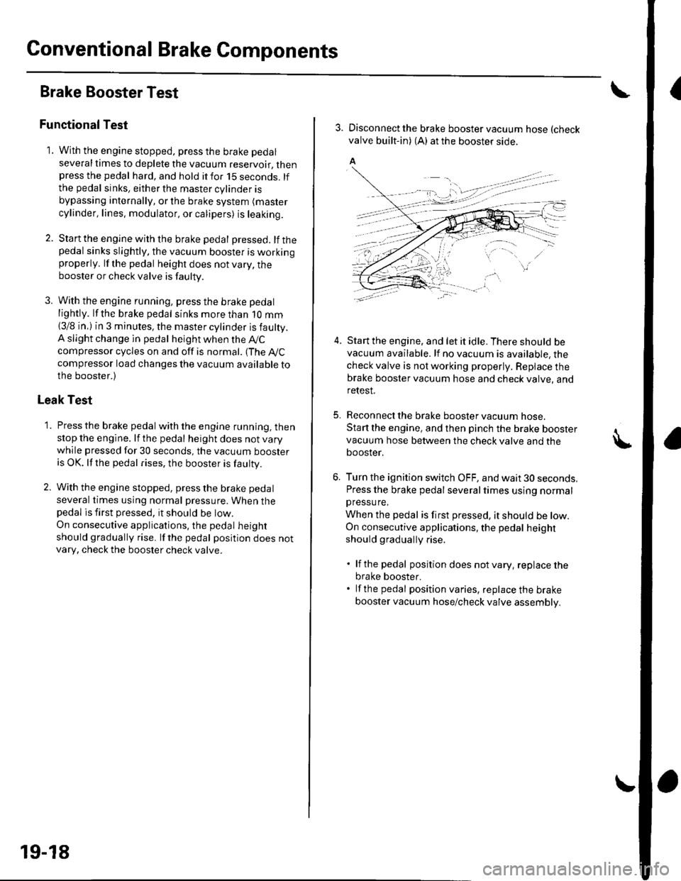
IBrake Booster Test
Functional Test
1. With the engine stopped, press the brake pedal
several times to deplete the vacuum reservoir, thenpress the pedal hard, and hold itfor 15 seconds. lfthe pedal sinks, either the master cylinder is
bypassing internally, or the brake system (master
cylinder, lines. modulator, or calipers) is leaking.
2. Start the engine with the brake pedal pressed. lf thepedal sinks slightly, the vacuum booster is workingproperly. lf the pedal height does not vary, thebooster or check valve is faulty.
3. With the engine running, press the brake pedal
lightly. lfthe brake pedal sinks more than 1O mm
{3/8 in, ) in 3 minutes, the master cylinder is faulty.A slight change in pedal height when the Ay'C
compressor cycles on and off is normal. (The A,/C
compressor load changes the vacuum available tothe booster.)
Leak Test
1. Press the brake pedal with the engine running, thenstop the engine. lf the pedal height does not vary
while pressed for 30 seconds, the vacuum boosteris OK. lf the pedal rises, the booster is faulty.
2. With the engine stopped, press the brake pedal
several times using normal pressure. When thepedal is first pressed, it should oe row.
On consecutive applications, the pedal height
should gradually rise. lfthe pedal position does notvarv, check the booster check valve.
19-18
3. Disconnect the brake booster vacuum hose (check
valve built-in) (A) at the booster side.
5.
4.Start the engine, and let it idle. There should bevacuum available. lf no vacuum is available, thecheck valve is not working properly. Repiace thebrake booster vacuum hose and check valve, andrelesI.
Reconnect the brake booster vacuum nose.
Start the engine, and then pinch the brake boostervacuum hose between the check valve and thebooster,
Turn the ignition switch OFF, and wait 30 seconds,Press the brake pedal several times using normalpressu re,
When the pedal is first pressed, it should be low.On consecutive applications, the pedal height
should gradually rise.
. lf the pedal position does notvary, replacethe
brake booster.. lf the pedal position varies, replace the brake
booster vacuum hose/check valve assembly.
Page 625 of 1139
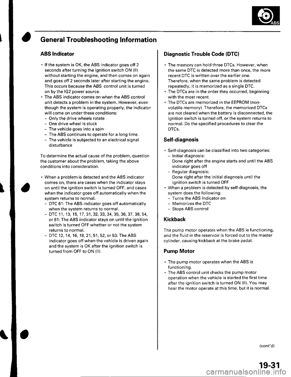
General Troubleshooting Information
ABS Indicator
. lf the system is OK,theABS indicator goes off 2
seconds after turning the ignition switch ON (ll)
without starting the engine, and then comes on again
and goes off 2 seconds later after starting the engine.
This occurs because the ABS control unitisturned
on by the lG2 power source.. The ABS indicator comes on when the ABS control
unit detects a problem in the system. However, even
though the system is operating properly, the indicator
will come on under these conditions:- Only the drive wheels rotate- One drive wheel is stuck- The vehicle goes into a spin- The ABS continues to operate for a long time.- The vehicle is subjected to an electrical signal
disturbance
To determine the actual cause of the problem, question
the customer about the problem. taking the above
condilions into consideration.
. When a Droblem is detected and lhe ABS indicator
comes on, there are cases when the indicator stays
on until the ignition switch is turned OFF, and cases
when the indicator goes off automatically when the
sYstem returns to normal.- DTC 61: The ABS indicator goes off automatically
when the system returns to normal.- DTC 11, 13,15,17 ,31,32,33, 34, 35, 36, 37, 38, 54,
or 81: The ABS indicator stays on until the ignition
switch is turned OFF whether or not the system
returns to normal.- DfC 12, 14, 16, 1a,21,51,52, or 53; The ABS
indicator goes off when the vehicle is driven again
and the system is OK after the ignition switch is
turned from OFF to ON {ll}.
Diagnostic Trouble Code {DTCI
. The memory can hold three DTCS. However, when
the same DTC is detected more than once, the more
recent DTC is written over the earlier one.
Therefore, when the same problem is detected
repeatedly, it is memorized as a single DTC.. The DTCs are in the order they occurred, beginning
with the most recent.. The DTCS are memorized in the EEPROM (non-
volatile memory). Therefore. the memorized DTCs
are not cleared when the battery is disconnected, the
ignition switch is turned off, or the system returns to
normal. Do the specified procedures to clear the
DTCs.
Self-diagnosis
. Self-diagnosis can be classified into two categories:- Initial diagnosis:
Done right after the engine starts and until the ABS
indicator goes off- Regular diagnosis:
Done rightafterthe initial diagnosis until the
ignition switch is turned OFF. When a problem is detected by self-diagnosis, the
system does the following:- Turns the ABS indicator on- Memorizes the DTC- Stops ABS control
Kickback
The pump motor operates when the ABS is functioning,
and the fluid in the reservoir is forced out to the master
cylinder, causing kickback at the brake pedal.
Pump Motor
. The pump motor operates when the ABS is
functioning.. The ABS control unit checks the pump motor
operation when the vehicle is started the first time
after the ignition switch is turned ON (ll). You may
hear the motor operate at this time, but it is normal.
(cont'd)
19-31
Page 832 of 1139
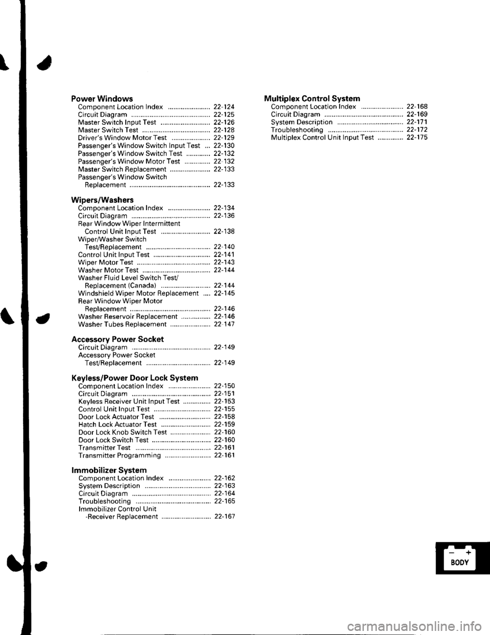
Power WindowsComponent Location Index ..........
circuit Diagram . .. ............... .........:.::::.::::.:Master Switch Input Test ...........................Master Switch TestDriver's Window Motor Test .....................
Passenger's Window Switch lnput Test ...Passenger's Window Switch Test .............
Passenger's Window Motor Test ..............
lMaster Switch Replacement ......................
Passenger's Window SwitchReplacement
Wipers/WashersComponent Location Index .......................
Circuit DiagramRear Window Wiper Intermiftent
Control Unit Input Test ...........................Wiper/Washer SwitchTesVReplacementControl Unit Input Test ...............................Wiper Motor Test
Washer Motor TestWasher Fluid Level Switch TesV
Replacement (Canadal ..........................
Windshield Wiper Motor Replacement ....
Rear Window Wiper MotorReplacementWasher Reservoir Replacement ................
Washer Tubes Beplacement ......................
Accessory Power SocketCircuit Diagram ......... 22-149
Accessory Power Socket
TesVReplacement ................................... 22-1 49
Keyless/Power Door Lock System
Component Location Index ....................... 22-150
Circuit Diagram ......... 22-151Keyless Receiver Unit InputTest ............... 22-153
Control Unit Input Test ............................... 22-155
Door LockActuatorTest .........,.......,..,.,..... 22-158Hatch LockActuatorTest ........................... 22-159
Door Lock Knob Switch Test ...................... 22-160
Door Lock Switch Test ................................ 22-160
Transmitter Test ....... 22-161
Transmitter Programming ......................... 22-161
Multiplex Control SystemComponent Location Index ...........
circuit Diagram ...... ........................::.:..:.::.:
Svstem DescriDtionTroubleshootingMultiolex Control Unit InDut Test .............
22 12422-12522-12622-12822-129
22- t30
22-13222 13222-133
22-133
22-134
22-138
22-14022-14122-14322-144
22-14422-145
22-14622-14622 147
22,16422-16922-17'l22,11222-175
lmmobilizer Systemcomponent Location Index ...........
System Description ....... ............. ..:..:..:.:...
Circuit DiagramTroubleshootinglmmobilizer Control Unit-Receiver Replacement ...........................
22-16222-16322-164
22-167
Page 843 of 1139
![HONDA CIVIC 2002 7.G Workshop Manual Relay and Control Unit Locations
Door and Seat
Drivers Door:
Passengers Seat:
l\:
].\
POWER WINDOW MASTER SWITCHlHas built-in control unit)
22-12 HONDA CIVIC 2002 7.G Workshop Manual Relay and Control Unit Locations
Door and Seat
Drivers Door:
Passengers Seat:
l\:
].\
POWER WINDOW MASTER SWITCHlHas built-in control unit)
22-12](/img/13/5744/w960_5744-842.png)
Relay and Control Unit Locations
Door and Seat
Driver's Door:
Passenger's Seat:
l\:
].\
POWER WINDOW MASTER SWITCHlHas built-in control unit)
22-12