differential HONDA CIVIC 2002 7.G Workshop Manual
[x] Cancel search | Manufacturer: HONDA, Model Year: 2002, Model line: CIVIC, Model: HONDA CIVIC 2002 7.GPages: 1139, PDF Size: 28.19 MB
Page 19 of 1139
L
v
2-7
OE
a
o
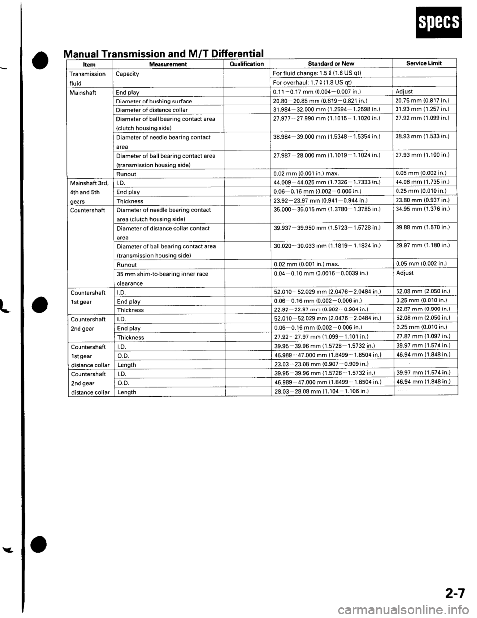
nual Transmission and M/T Differential
ItemM€asurementOualificationStandard or NewSe.vice Limit
Transmission
fluid
CapacityFor fluid change: 1.5 0 (1.6 US qt)
For overhaul: 1.7 011.8 US qt)
MainshaftEnd plav0.1 'l -0.17 mm (0.004 0.007in.)Adiust
Diameter of bushing surface20.80 20.85 mm {0.819 0.821 in.)20.75 mm 10.817 in.)
Diameter of distance collar31.984-32.000 mm (1.2594 1.2598 in.)3'1.93 mm (1.257 in.)
Diameter of ball bearing contact area
(clutch housing side)
27.977 27s90 mm \1.1015 - 1.1020 in.)27.92 mm (1.099 in.)
Diameter of needle bearing contact
area
38.984 39.000 mm (1.5348 '1.5354 in.)38.93 mm (1.533 4n.)
Diameter of ball bearing contact area
(transmission housing side)
27.987 28.000 mm (1.10'19 1.1024 in.)27.93 mm {1.100 in.)
Runout0.02 mm (0.001 in.) max.0.05 mm (0.002 in.)
Mainshaft 3rd,
4th and sth
gears
t.D.44.009 44.025 mm 11.7326 1.7333 in.)44.08 mm (1.735 in.)
End play0.06 0.16 mm {0.002 0.006;n.)0.25 mm (0.010 in.)
Thickness23.92 23.97 mm (0.94'1 0.944 in.)23.80 mm (0.937 in.)
CountershaftDiameter of needle bearing contact
area (clutch housing side)
35.000-35.015 mm (1.3780 '1.3785 in.)34.95 mm (1.376 in.)
Diameter of distance collar contact
alea
39.937 39 950 mm (1.5723 1.512ain.|39.88 mm (1.570 in.)
Diameter of ball bearing contact area
(transmission housing side)
30.020-30.033 mm (1.1819- 1.1824 in.)29.97 mm (1.180 in.)
Runout0.02 mm {0.001 in.) max.0.05 mm (0.002 in.)
35 mm shim-to'bearing inner race
clearance
0.04 0.10 mm (0.0016 0.0039 in.)Adjust
CountershaftLD.52.010 52.029 mm (2.0476-2.0484 in.i52.08 mm (2.050 in.)
End play0.06 0.16 mm (0.002 0.006 in.)0.25 mm 10.010 in.)
Thickness22.92 22.91 $m 10.902 -0.904 in.)22.87 mm (0.900 in.)
Countershaft
2nd gear
t.D.52.010 52.029 mm (2.0476 2.0484 in.)52.08 mm {2.050 in.}
End play0.06 0.16 mm (0.002 0.006 in.)0.25 mm 10.010 4n.)
Thickness21.92 27.91 mtn \1.099 1.101 in.)27.87 mm 11.097 in.)
Countershaft'l st gear
distance collar
LD.39.95 39.96 mm (1.572a 1.5132 in.)39.97 mm (1.574 in.)
o.D.46.989- 47.000 mm (1.8499- 1.8504 in.)46.94 mm (l.848 in.)
Length23.03 23.08 mm (0.907-0.909 in.i
Countersha{l
2nd gear
distance coliar
l.D.39.95 39.96 mm {1.5728'- 1.5732 in.l39.97 mm (1.574 in.)
o.o.46.989 47.000 mm (1.8499 1.8504 in.)46.94 mm (1.848 in.)
Length28.03 28.08 mm (l.104 1.106in.)
Page 20 of 1139
anuat I ransmcont'
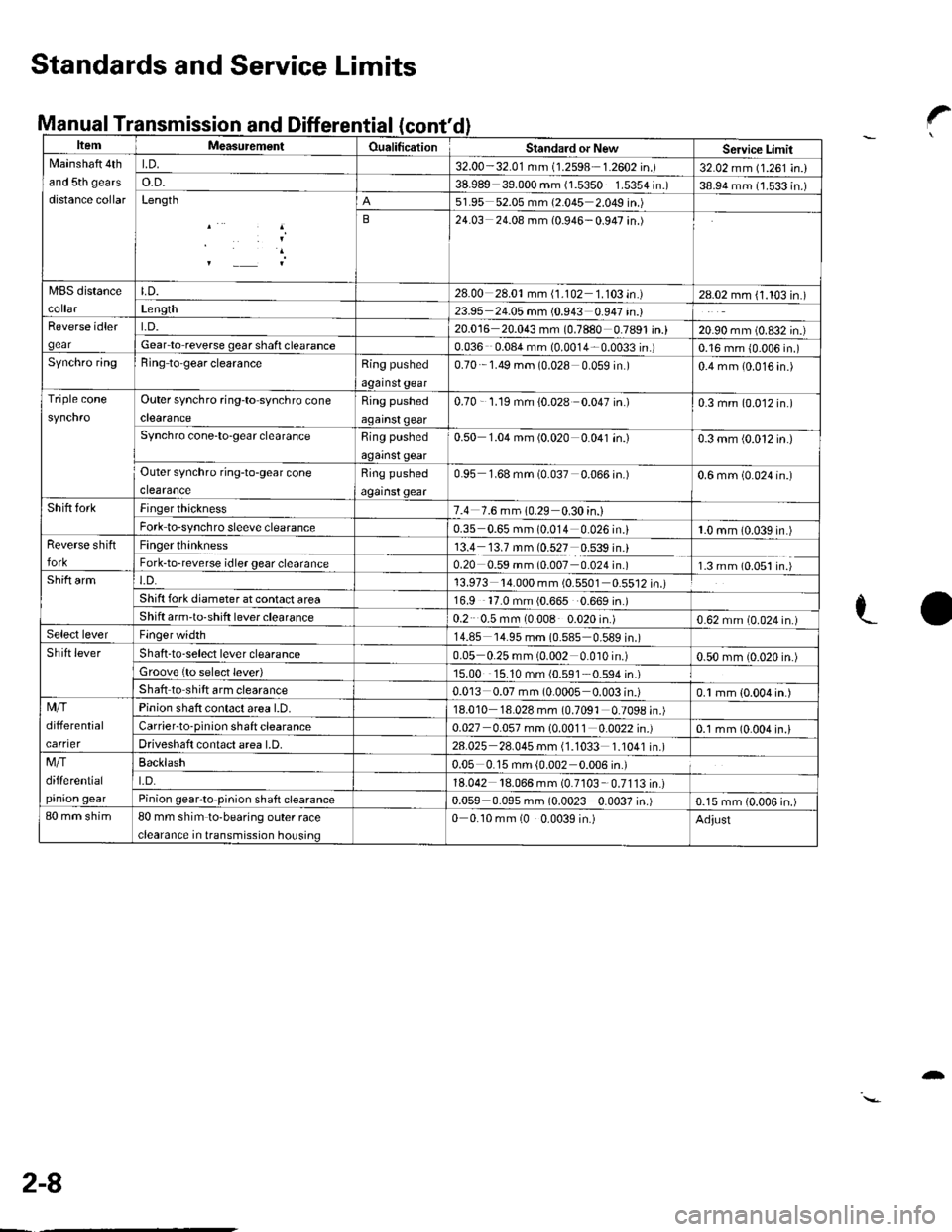
ItemMeasutemenlOualificationStandard or NewServicc LimitNlainshaft 4th
and 5th gears
distance collar
LD.32.00-32.01 mm (1.2598 1.2602 in.)32.02 mm (1.261 in.)o.D.38.989 39.000 mm (1.5350 1.5354 in.)38.94 mm (1.533 in.)Length51.95 52.05 mm (2.045 2.049 in.)
B24.03 24.08 mm (0.946-0.947 in.)
MBS distanceLD.28.00 28.01mm (1.102 1.103 in.)28.02 mm (1.103 in.)Len9th23.95 24.05 mm (0.943 0.947 in.)Reverse idler
gear
t.D.20.016 20.043 mm (0.7880 0.7891 in.)20.90 mm (0.832 in.)Gear lo reverse gear shafi clearance0.036 0.08a mm (0.0014 0.0033 in.)0.16 mm {0.006 in.)Synchro ringBing to'gear clearanceRing pushed
against gear
0.70 1.49 mm (0.028 0 059 in )0.4 mm (0.016 4n.)
Triple coneOuter synchro ring-to synchro cone
clearance
Ring pushed
against qear
0.70 - '1.19 mm {0.028 0.047 in.)0.3 mm (0.012 in.)
Synchro cone-to-gear clearanceRing pushed
against gear
0.50 1.04 mm (0.020 0.041 in.)0.3 mm (0.012 in.)
Outer synchro ring-to-gear cone
clearance
Ring pushed
against gear
0.95 1.68 mm (0.037 0.066 in.)0.6 mm (0.024 in.)
Shift forkFinger thickness7.4 7.6 mm 10.29 0.30 in.)Fork to-synchro sleeve clearance0.35 0.65 mm (0.014 0.026 in.i1.0 mm (0.039 in.)Reverse shift
fork
Finger thinkness13.4 13.7 mm (0.527 0.539 in.)Fork-to-reverse idler gear clearance0.20 0.59 mm (0.007 0.024 in.)1.3 mm (0.051 in.)Shift armt.D.13.973 '14.000 mm (0.5501 0.5512 in.)Shift fork diameter at conlact area16.9 '17.0 mm (0.665 0.669 in.)Shift arm'to-shift lever clearance0.2 0.5 mm (0.008 0.020 in.)0.62 mm (0.024 in.)Select leverFinger width14.85 '14.95 mm (0.585 0.589 in.)Shift leverShaft -to-select lever clearance0.05 0.25 mm (0.002 0.010 in.)0.50 mm (0.020 in.)Groove {to select lever)15.00 15.10 mm {0.591 0.594 in.)
Shaft to shift arm clearance0.013 0.07 mm (0.0005 0.003 in.)0.1 mm {0.004 in.)Mfi
differential
carrier
Pinion shaft contact area l.D.18.010 18.028 mm (0.7091 0.7098 in.)Carrier-to-pinion shaft clearance0.027 0.057 mm (0.0011 0.0022 in.)0.1 mm (0.004 in.lDriveshaft contact area LD.28.025 28.045 mm (1.1033 1.1041 in.)Mfi
differential
pinion qear
Backlash0.05 0.15 mm {0.002 0.006 in.)
t.D.18.042 18.066 mm (0.7103 0.7113in.)Pinion gearto pinion shaft clearance0.059 0.095 mm (0.0023 0.0037 in.)0.15 mm (0.006 in.)80 mm shim80 mm shim to-bearing outer race
clearance in transmission housing
0 0.10 mm (0 0.0039 in.)Adjust
Standards and Service Limits
Manual Transmission and Differential?
LO
2-8
-
Page 91 of 1139
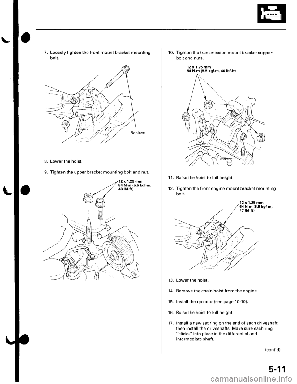
7. Loosely tighten the front mount bracket mounting
bolt.
Lower the hoist.
Tighten the upper bracket mounting bolt and nut.
8.
9.
10. Tighten the transmission mount bracket support
bolt and nuts.
12 x 1.25 mm54 N m {5.5 kgt m, 40 lbf.ft}
Raise the hoist to full height.
Tighten the front engine mount bracket mounting
bolt.
'l '1.
't2.
12 x 1.25 rnrn64 N.m {6.5 kgf.m,47 tbt.ftl
13. Lower the hoist.
14. Remove the chain hoist from the engine.
'15. Installthe radiator (see page 10-10).
'16. Raise the hoist to full height.
17. Install a new set ring on the end of each driveshaft,
then install the driveshafts. Make sure each ring"clicks" into place in the differential and
intermediate shaft.
(cont'd)
:l
5-11
Page 235 of 1139
Fuel and Emissions Systems
(
(
(
System Descriptions (cont'dl
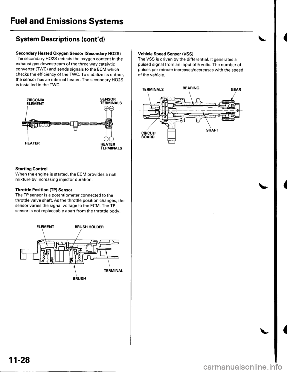
Secondary Heated Oxygen Sensor (Secondary HO2S)
The secondary HO2S detects the oxygen content in the
exhaust gas downstream of the three way catalytic
converter (TWC) and sends signals to the ECM which
checks the efficiency of the TWC. To stabilize its output,
the sensor has an internal heater. The secondarv HO2S
is installed in the TWC.
ztRcoNtaELEMENTSENSORTERMINALS
HEATERTERMINALS
Starting Control
When the engine is started, the ECM provides a rich
mixture by increasing injector duration.
Throttle Position ITP) Sensor
The TP sensor is a potentiometer connected to the
throttle valve shaft. As the throttle position changes, the
sensor varies the signal voltage to the ECM. The TP
sensor is not replaceable apart from the throftle body.
ELEMENTBRUSH HOLDER
gRUSH
11-28
Vehicle Speed Sensor (VSS)
The VSS is driven by the differential. lt generates apulsed signal from an input of 5 volts. The number ofpulses per minute increases/decreases with the speed
of the vehicle.
BEARING
Page 411 of 1139
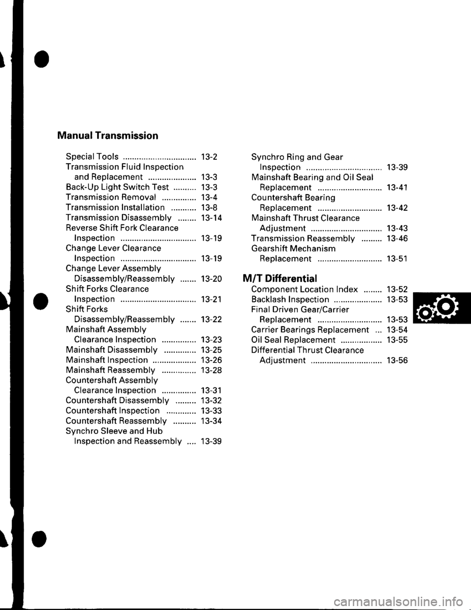
Manual Transmission
SpecialTools
Transmission Fluid Inspection
and Reo1acement ...................-.
Back-Up Light Switch Test ..........
Transmission Removal
Transmission Installation ...........
Transmission Disassemblv ........
Reverse Shift Fork Clearance
lnsoection
Change Lever Clearance
lnsoection
Change Lever Assembly
Disassembly/Reassembly .......
Shift Forks Clearance
Inspection
Shift Forks
Disassembly/Reassembly .......
Mainshaft Assemblv
Clearance Inspection
Mainshaft Disassembly
Mainshaft lnsoection
Mainshaft Reassembly
Countershaft Assemblv
Clearance Inspection
Countershaft Disassembly .........
Countershaft Inspection .............
Countershaft Reassembly ..........
Synchro Sleeve and Hub
Inspection and Reassembly ....
Synchro Ring and Gear
Insoection ....... 13-39
Mainshaft Bearing and Oil Seal
Replacement ........................,... 13-41
Cou ntershaft Bearing
ReDlacement .. 13-42
Mainshaft Thrust Clearance
Adiustment ..... 13-43
Transmission Reassemblv ......... 13-46
Gearshift Mechanism
Replacement ............................ 13-51
M/T Differential
Comoonent Location Index ........ 13-52
Backlash Inspection ..................... 13-53
Final Driven Gear/Carrier
Replacement .. 13-53
Carrier Bearings Replacement ... 13-54
Oil Seal Replacement .................. 13-55
Differential Thrust Clearance
Adiustment ..... 13-56
13-2
| 5-J
tJ-5
13-4
I J-at
13-14
13- 19
13- 19
13-20
13-21
13-22
13-23't3-25
13-26
| 5-2.5
13-31
13-32
13-33
13-34
13-39
Page 428 of 1139
Manual Transmission
Transmission Disassembly (cont'd)
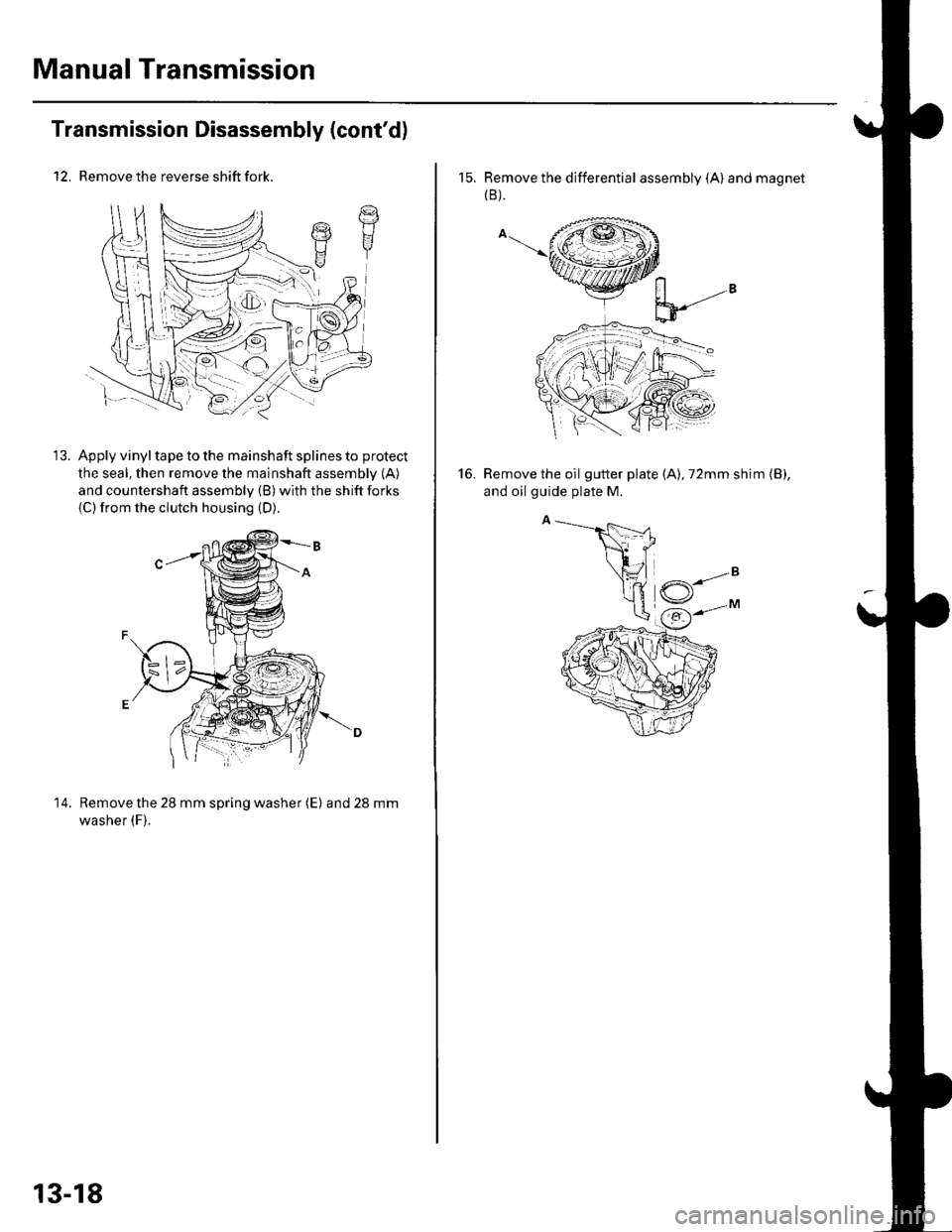
12. Remove the reverse shift fork.
Apply vinyl tape to the mainshaft splines to protect
the seal, then remove the mainshaft assembly (A)
and countershaft assembly (B) with the shift forks
{C)from the clutch housing (D).
14. Remove the 28 mm spring washer (E) and28mm
washer (F).
t7t1I
13-18
15. Remove the differential assembly (A) and magnet(B ).
Remove the oil gutter plate (A), 72mm shim (B),
and oil guide plate M.
16.
Page 451 of 1139
Mainshaft Bearing and Oil Seal Replacement
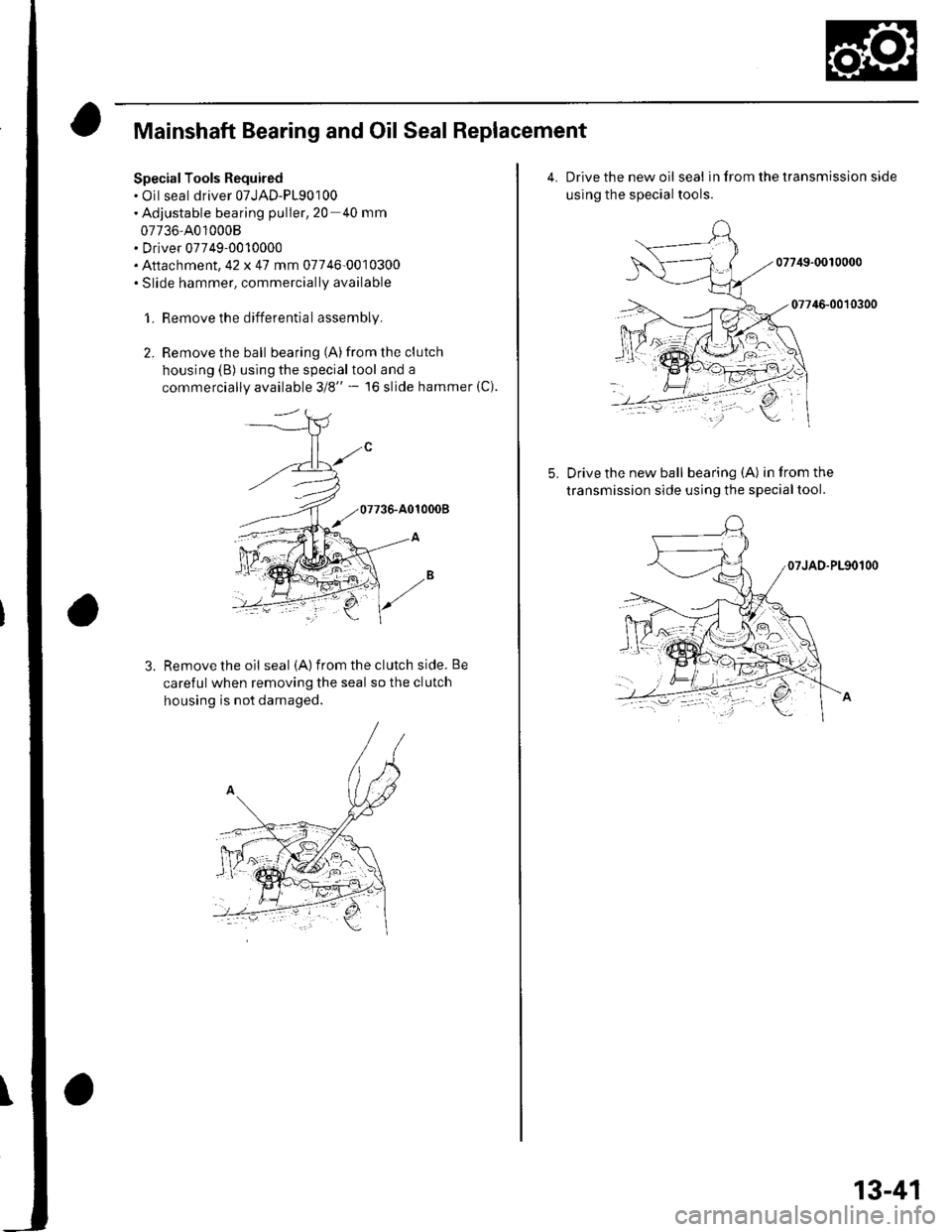
Special Tools Required. Oil seal driver 07JAD-P190100. Adjustable bearing puller,20 40 mm
07736-4010008. Driver 07749-0010000. Attachment,42 x 47 mm 07746-0010300. Slide hammer, commercially available
1. Remove the differential assembly,
2. Remove the ball bearing (A)from the clutch
housing (B) using the specialtool and a
commercially available 3/8" - l6 slide hammer (C).
Remove the oil seal (A) from the clutch side. Be
careful when removing the seal so the clutch
housing is not damaged.
4.Drive the new oil seal in from the transmission side
using the special tools.
07749-0010000
07746-0010300
Drive the new ball bearing (A) in from the
transmission side using the specialtool.
13-41
Page 456 of 1139
Manual Transmission
Transmission Reassembly
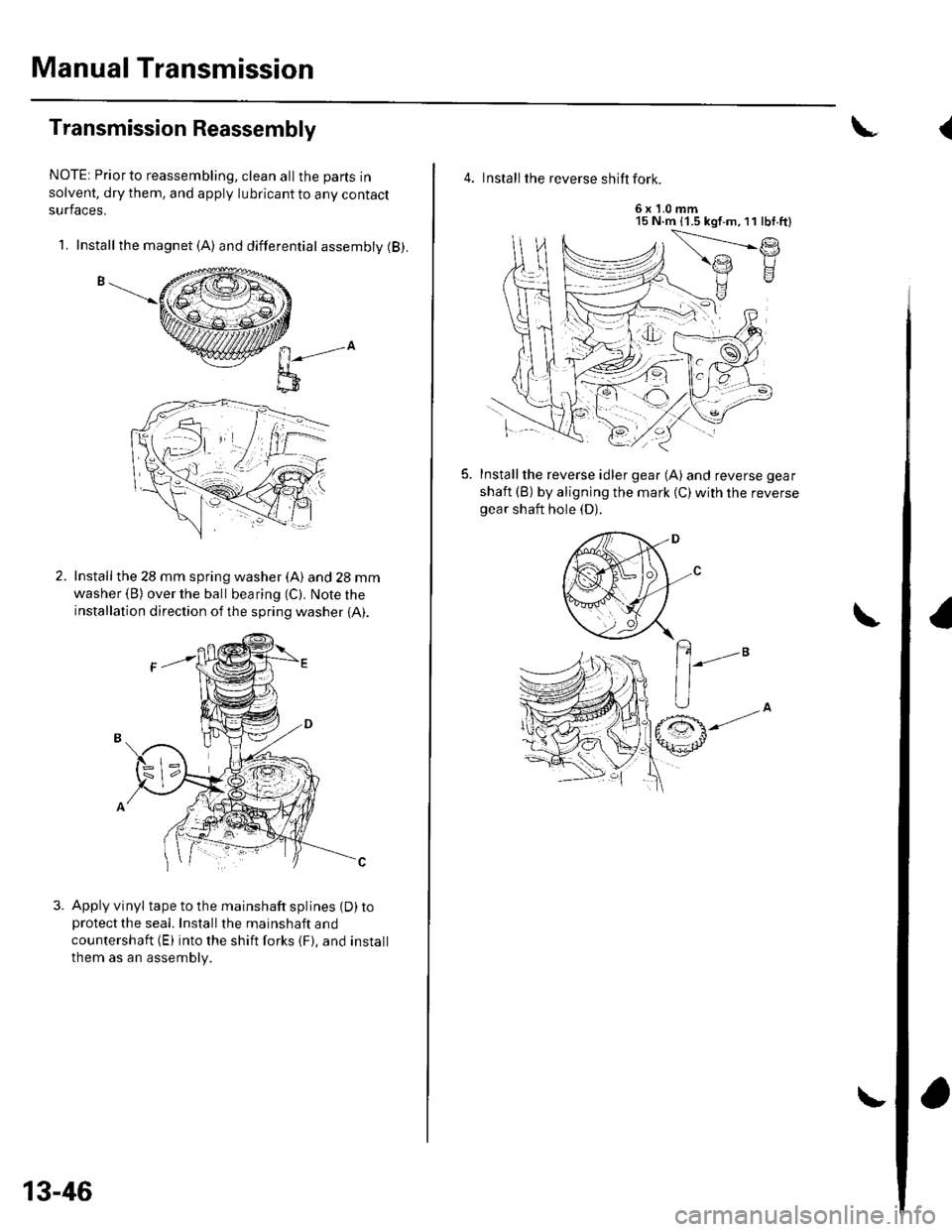
NOTE: Priorto reassembling, clean allthe parts in
solvent, dry them, and apply lubricant to any contact
surfaces.
1. Install the magnet (A) and differential assembly (B).
n-",-o
l;-D
Install the 28 mm spring washer (A) and 28 mm
washer (B) over the ball bearing (C). Note the
installation direction of the spring washer {A).
Apply vinyl tape to the mainshaft splines (D) toprotectthe seal. Installthe mainshaft and
countershaft (E) into the shift forks {F}. and install
them as an assembly.
13-46
\
4. Install the reverse shift fork.
6x1.0mm15 N.m (1.5 kgf.m,11 lbf.ft)
f.)
Installthe reverse idler gear (A) and reverse gear
shaft (B) by aligning the mark {C)with the reversegear shaft hole (D).
(
Page 462 of 1139
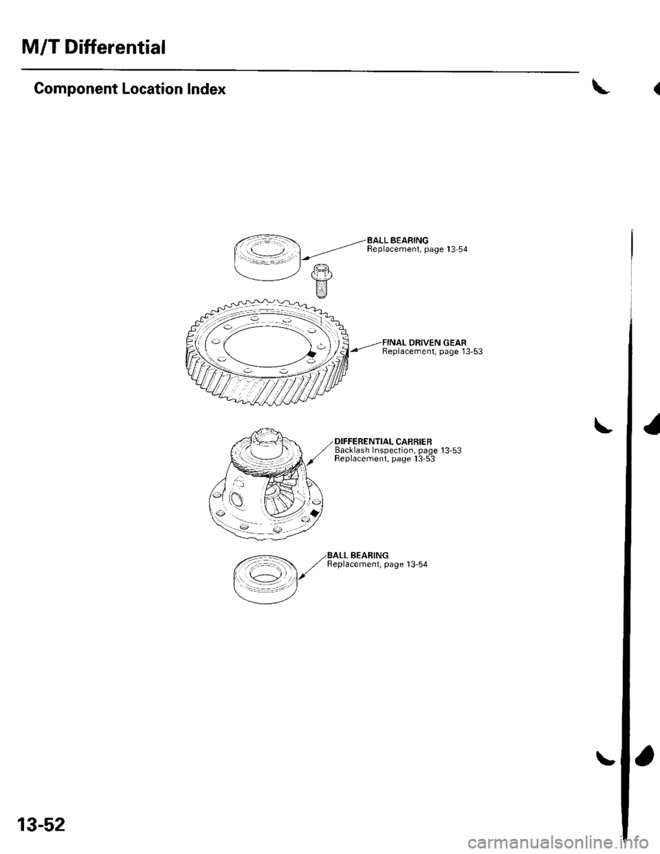
M/T Differential
Component Location Index
DRIVEN GEARBeplacement, page 13-53
Backlash Insoection. oaoe 13-53Feplacemeni, paoe I 3-5-3
\
\
,<-=- ,/BALL BEARING
/ ,/ Beplacemenl, page 13-54
I \c1 l/
=/
13-52
(
I
Page 463 of 1139
\
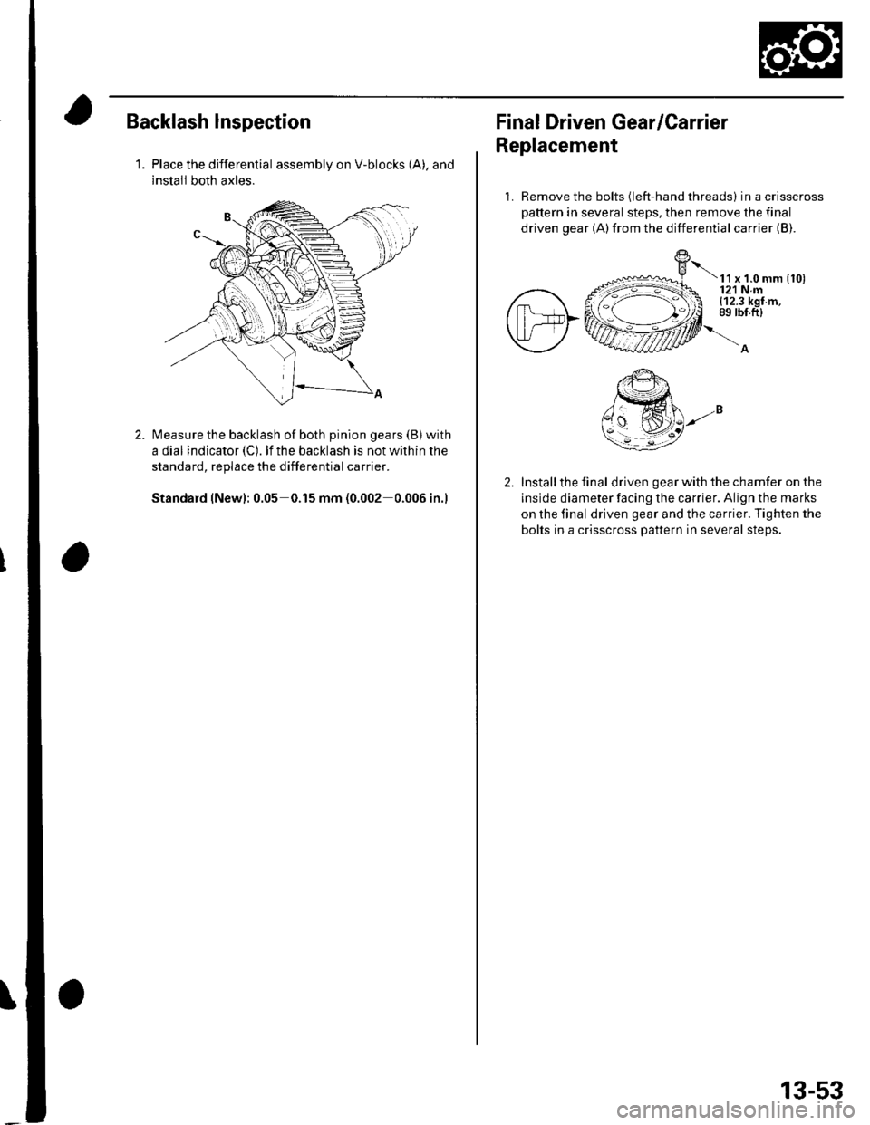
Backlash lnspection
1.Place the differential assembly on V-blocks (A), and
install both axles.
Measure the backlash of both pinion gears (B) with
a dial indicator (C). lf the backlash is not within the
standard, replace the differential carrier.
Standard (New): 0.05 0.15 mm (0.002 0.006 in.)
Final Driven Gear/Carrier
Replacement
1. Remove the bolts (left-hand threads) in a crisscross
pattern in several steps, then remove the final
driven gear (A)from the differential carrier {B).
t x t.o mm {to)121 Nm(12.3 kgf m,89 rbt.ft)
Install the final driven gear with the chamfer on the
inside diameter facing the carrier. Align the marks
on the final driven gear and the carrier. Tighten the
bolts in a crisscross pattern in several steps.
13-53