buttons HONDA CIVIC 2002 7.G Workshop Manual
[x] Cancel search | Manufacturer: HONDA, Model Year: 2002, Model line: CIVIC, Model: HONDA CIVIC 2002 7.GPages: 1139, PDF Size: 28.19 MB
Page 44 of 1139
Starter Replacement
1. Make sure you have the anti-theft code for the radio.
then write down the frequencies for the radio's
preset buttons.
2. Disconnect the negative cable from the battery first,
then disconnect the positive cable.
3. Disconnect the knock sensor connector.
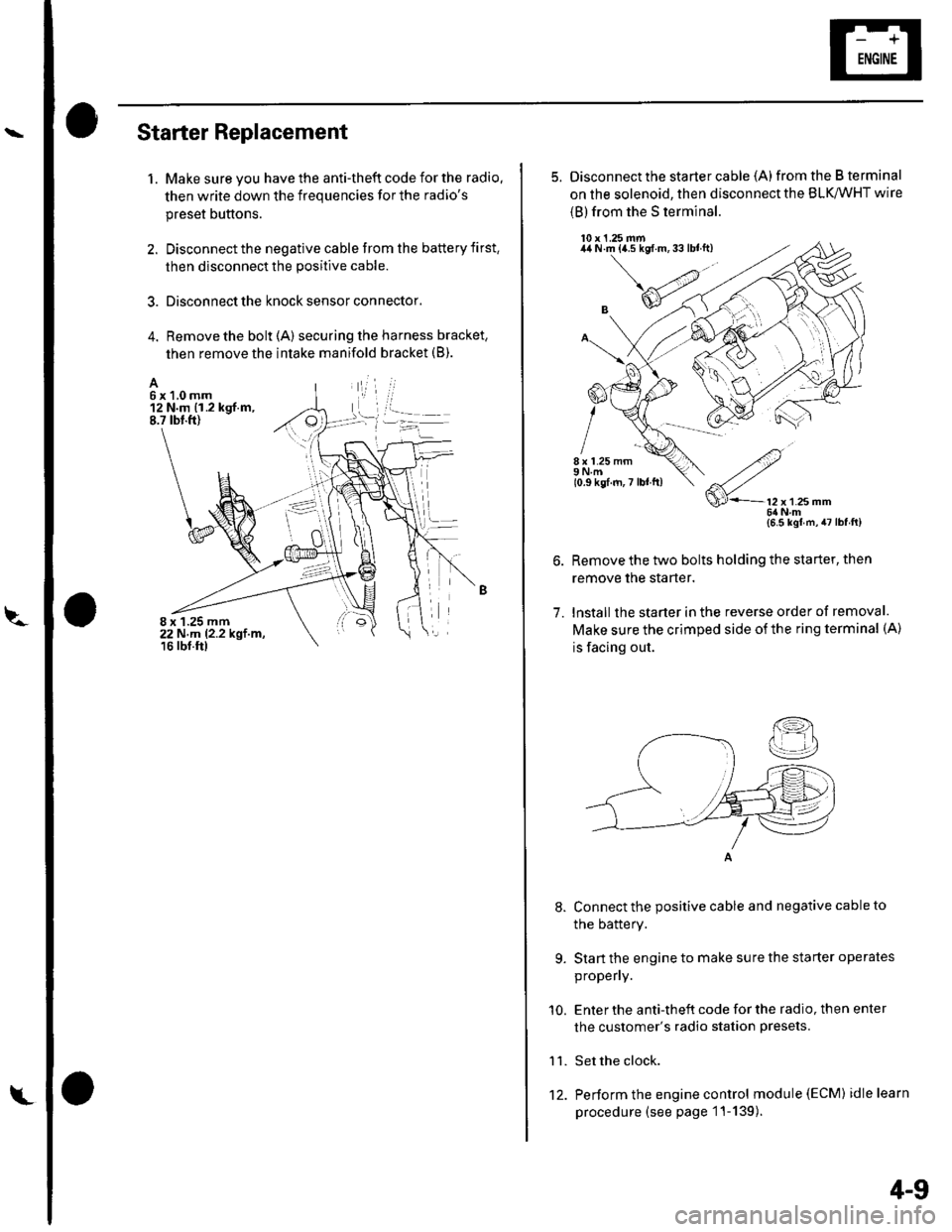
4. Remove the bolt (A) securing the harness bracket,
then remove the intake manifold bracket (B).
A6x1,0mm12 N.m {1.2 kgf.m,8.7 tbt.ft)
8 x 1.25 mm22 N,m 12.2 kgt.m,16 rbf.ftl
L't2.
4-9
5. Disconnect the starter cable (A)from the B terminal
on the solenoid, then disconnect the BLK,/WHT wire
{B) from the S terminal.
10 x 1.25 mm44 N.m {a.5 kgf.m,33lblft)
8 x 1.25 mm9Nm10.9 kgf.m,7 lbl ft)
7.
9.
'10.
11.
2
S'-12x12smm6ilNm{6.5 kgl m,47lbfft)
Remove the two bolts holding the starter, then
remove the starter.
lnstall the starter in the reverse order of removal.
Make sure the crimped side of the ring terminal (A)
is facing out.
Connect the positive cable and negative cable to
the batterY.
Start the engine to make sure the starter operates
propeny.
Enter the anti-theft code for the radio, then enter
the customer's radio station presets.
Set the clock.
Perform the engine control module (EcM) idle learn
procedure (see page 1 '1- 139 ).
I
Page 64 of 1139
l\-Alternator Replacement
1. Make sure you have the anti-theft code for the radio,
then write down the frequencies for the radio'spreset buttons,
2. Disconnect the negative cable from the battery first,
then disconnect the positive cable.
3. Remove the front bumper (see page 20-85).
4. Remove the right side headlight (see page 22-79).
5. Remove the reserve tank from the bracket.
6. Remove the drive belt (see page 4-26).
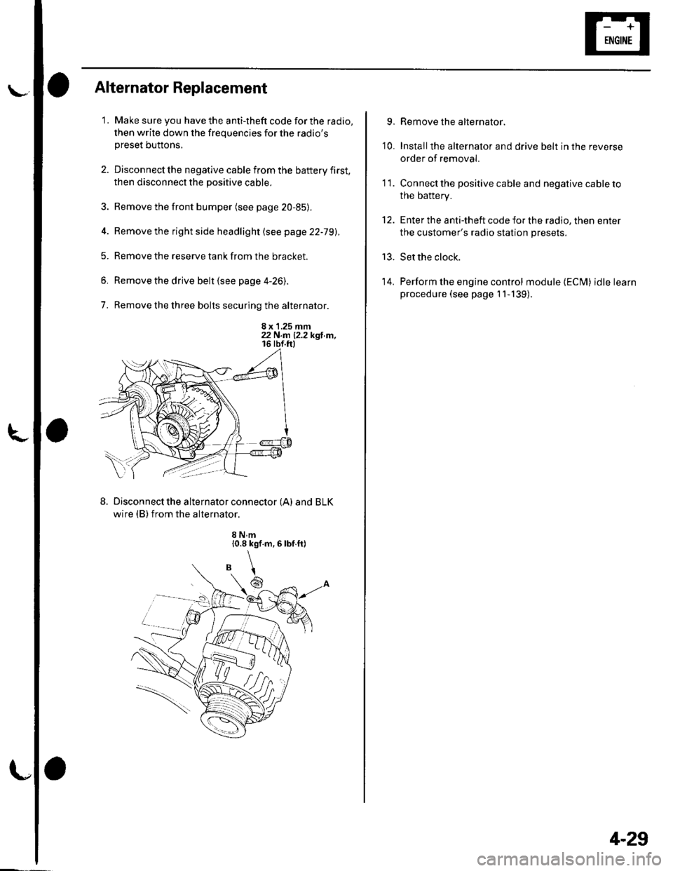
7. Remove the three bolts securing the alternator.
8 x 1.25 mm22 N.n 12.2 kgl.m,
Disconnect the alternator connector (A) and BLK
wire (B) from the alternator.
8 N.m10.8 kgf.m,6lbf.ft)
\
6
'I 1.
9.
10.
13.
14.
Remove the alternator.
Installthe alternator and drive belt in the reverse
order of removal.
Connect the positive cable and negative cable to
the battery.
Enter the anti-theft code for the radio, then enter
the customer's radio station presets.
Set the clock.
Perform the engine control module {ECM) idle learn
procedure (see page 11-139).
tt.
4-29
Page 82 of 1139
Engine Assembly
I
Engine Removal
Special Tools Required
Front subframe adapter EOS02C00001 1
NOTE:. Use fender covers to avoid damaging painted
surfaces.. To avoid damage, unplug the wiring connectors
carefully while holding the connector portion.. Mark all wiring and hoses to avoid misconnection.
Also, be sure that they do not contact other wiring orhoses, or interfere with other parts.
1. Secure the hood in the wide open position (support
rod in the lower hole).
2. Make sure you have the anti-theft code for the radio,
then write down the frequencies for the radio'spreset buttons.
3. Disconnect the negative cable from the battery first,then disconnect the positive cable.
4. Remove the battery.
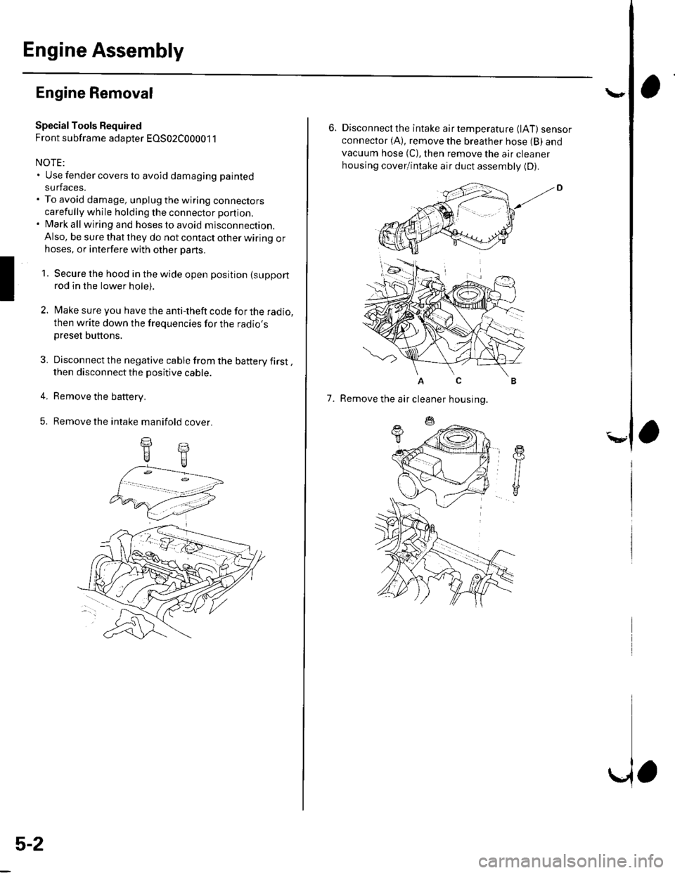
5. Remove the intake manifold cover.
II
5-2
\,
6. Disconnectthe intake airtemperature (lAT) sensorconnector (A), remove the breather hose (B) and
vacuum hose (C), then remove the air cleaner
housing cover/intake air duct assemblv (D).
AC
7. Remove the air cleaner housing.
Page 404 of 1139
Slave Cylinder Replacement
NOTE:. Use fender covers to avoid damaging painted
surfaces.. Do not spill brake fluid on the vehicle; it may damage
the paint; if brake fluid does contact the paint, wash it
off immediately with water.
1. Write down the frequencies for the radio's preset
buttons. Disconnect the negative ( ) cable first,
then the positive (+)cable from the battery.
Remove the battery.
2. Remove the battery tray.
a
Remove the air cleaner housing cover and the air
cleaner housing (see step 6 on page 5-2).
Remove the intake air duct (see step 8 on page 5-3) .
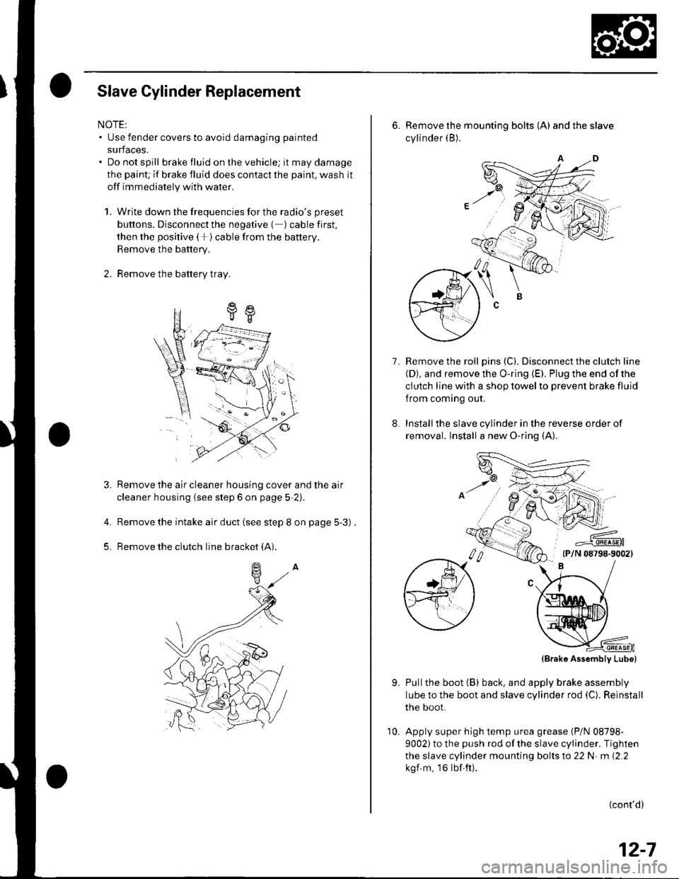
Remove the clutch line bracket (A).
4.
5.
6. Remove the mounting bolts (A) andtheslave
cylinder (B).
Remove the roll pins (C). Disconnect the clutch line(D), and remove the O-ring (E). Plug the end of the
clutch line with a shop towel to prevent brake fluid
f rom coming out.
Installthe slave cylinder in the reverse order of
removal. Install a new O-ring (A).
7.
,,6NJ'
=--#.q!4sEn(P/N 08798-90021
9.
(Brak6 Assembly Lube)
Pullthe boot (B) back, and apply brake assembly
lube to the boot and slave cylinder rod (C). Reinstall
the boot.
Apply super high temp urea grease (P/N 08798-
9002) to the push rod of the slave cylinder. Tighten
the slave cylinder mounting bolts to 22 N m (2.2
kgf m, 16lbf.ft).
(cont'd)
12-7
10.
Page 405 of 1139
Clutch
Slave Cylinder Replacement (cont'd)
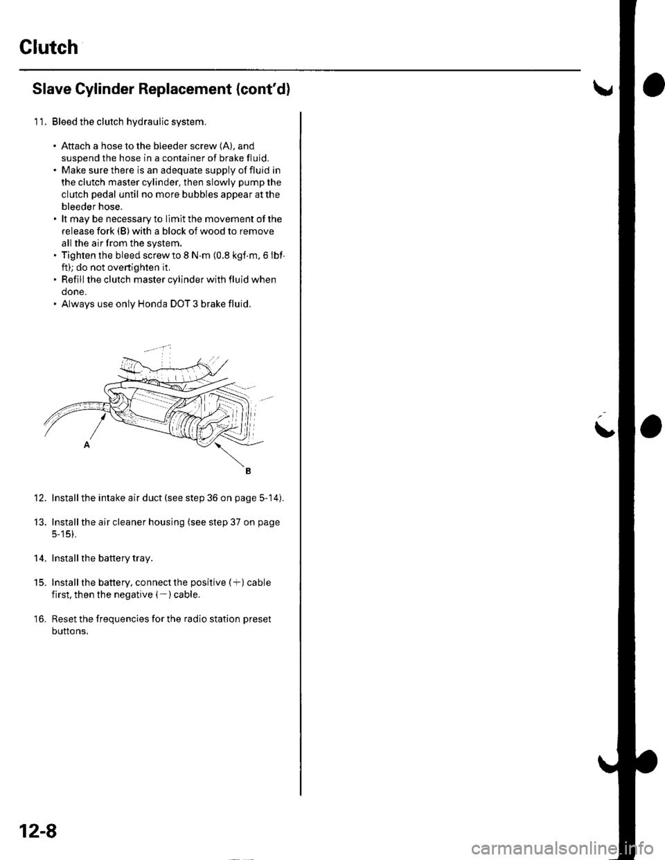
11. Bleed the clutch hydraulic system.
. Aftach a hose to the bleeder screw (A), and
suspend the hose in a container of brake fluid.. Make sure there is an adequate supply offluid in
the clutch master cylinder, then slowly pump the
clutch pedal until no more bubbles appear atthe
bleeder hose.. lt may be necessary to llmit the movement of the
release fork (B) with a block of wood to remove
all the air from the system.. Tighten the bleed screw to I N.m (0.8 kgf.m, 6 lbf
ft); do not ovenighten it,. Refill the clutch master cylinder with fluid when
done.. Always use only Honda DOT 3 brake fluid.
Install the intake air duct (see step 36 on page 5-14).
Installthe air cleaner housing (see step 37 on page
5-15).
Install the battery tray.
Install the battery, connect the positive (+) cable
first, then the negative (- ) cable.
Reset the frequencies for the radio station preset
buttons,
12.
13.
14.
t5.
16.
12-8
L
Page 414 of 1139
Manual Transmission
Transmission Removal
SpecialTools Required. Engine hanger adapter.2.0 to 2.4 liter VSB02C000015. Engine hanger VSB02C000018. Engine support hanger, A & Reds AAR'T 12566'. Subframe adaDter EOS02C000011 '
* Available through the Honda Tool and Equipment
Program 888-424-6857
NOTE: Use fender covers to avoid damaging painted
surfaces.
4.
1.
7.
Write down the frequencies for the radio's preset
buttons. Disconnect the negative ( ) cable first,
then the positive ( )cable from the battery.
Remove the battery.
Remove the intake manifold cover {see page g-3).
Remove the air cleaner housing (see page 1 1-162).
Remove the intake air duct {see step 8 on page 5-3).
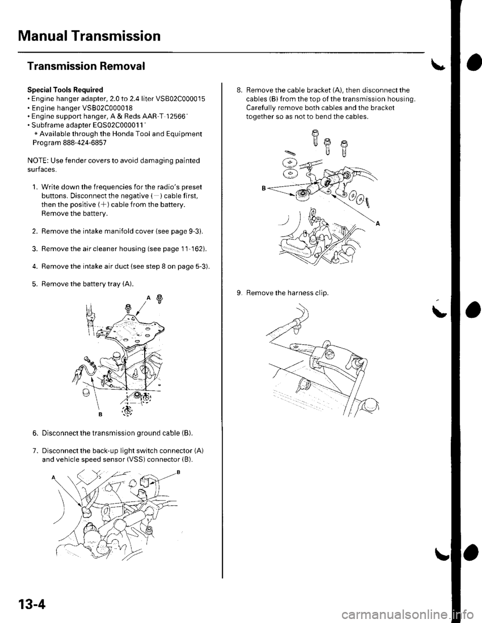
Remove the battery tray (A).
Disconnect the transmission ground cable (B).
Disconnect the back-up light switch connector (A)
and vehicle speed sensor (VSS) connector (B).
13-4
8. Remove the cable bracket (A). then disconnect the
cables (B) from the top of the transmission housing.
Carefully remove both cables and the bracket
together so as not to bend the cables.
9. Remove the harness clip.
I
HA @
ilB
Page 540 of 1139
Motor Removal/lnstallation
Bemoval
1. Make sure you have the anti-theft code for the radio,
then write down the frequencies for the preset
buttons.
2. Disconnect the negative cable from the battery, and
wait 3 minutes before beginning work.
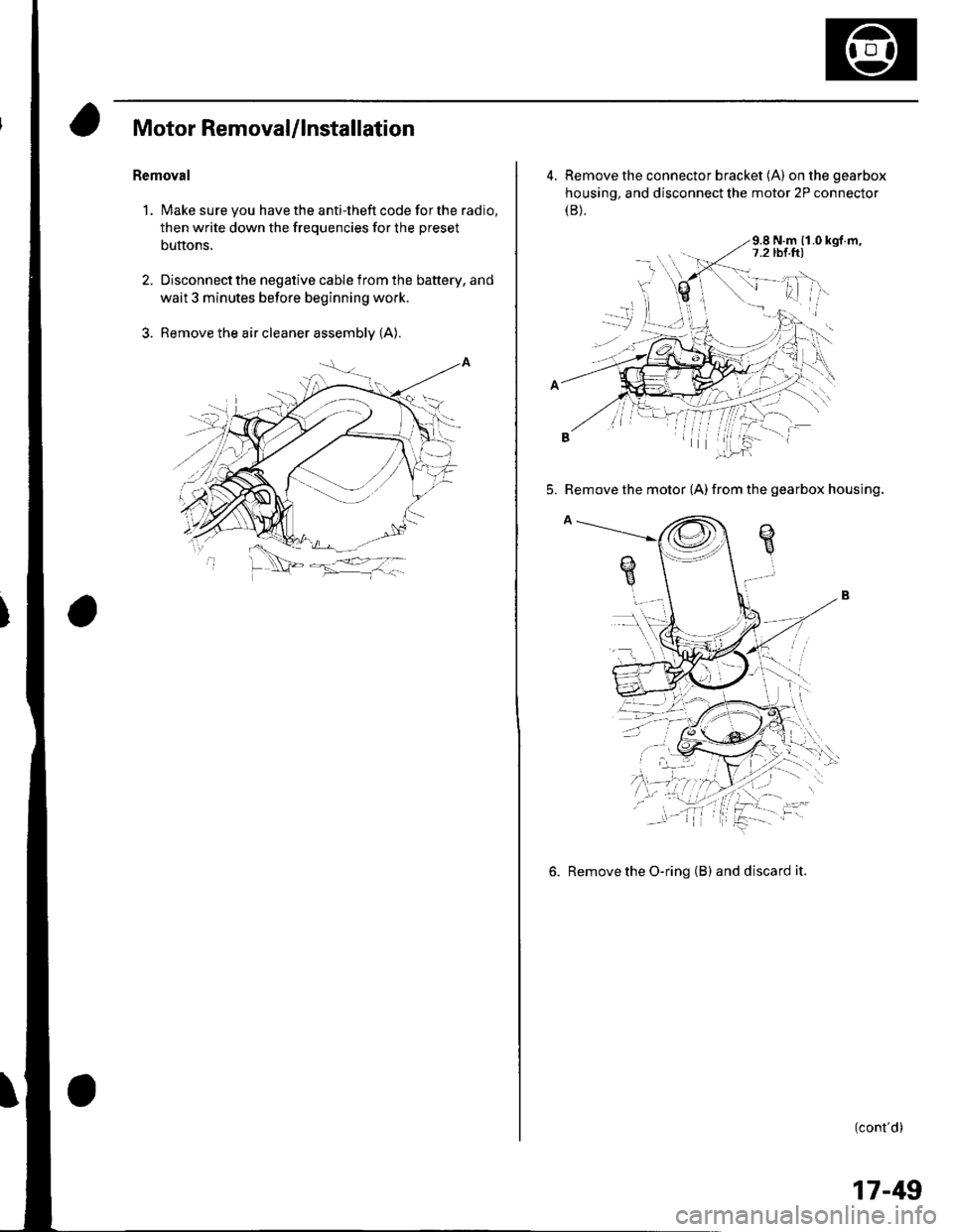
3. Remove the air cleaner assembly (A).
4. Remove the connector bracket (A) onthegearbox
housing, and disconnect the motor 2P connector(B).
9.8 N.m {1.0 kgf.m,
5. Remove the motor {A) from the gearbox housing.
6. Remove the O-ring (B) and discard it.
(cont'd)
17-49
Page 716 of 1139
Dashboard
Dashboard Center Panel Removal/lnstallation
NOTE:. Put on gloves to protect your hands.. When prying with a flat-tip screwdriver, wrap it with
protective tape, and apply protective tape around the
related parts, to prevent damage.. Take care not to scratch the dashboard and related
parts.
1. Make sure you have the anti-theft code for the radio,
the write down the frequencies for the preset
buttons.
Remove these items:
. Driver's dashboard lower cover (see page 20-59)
. Passenger's dashboard lower cover (see page
20-63).. Glove box (see page 20-63).. Shift lever trim {see page 20-61).
From the glove box and driver's dashboard Iower
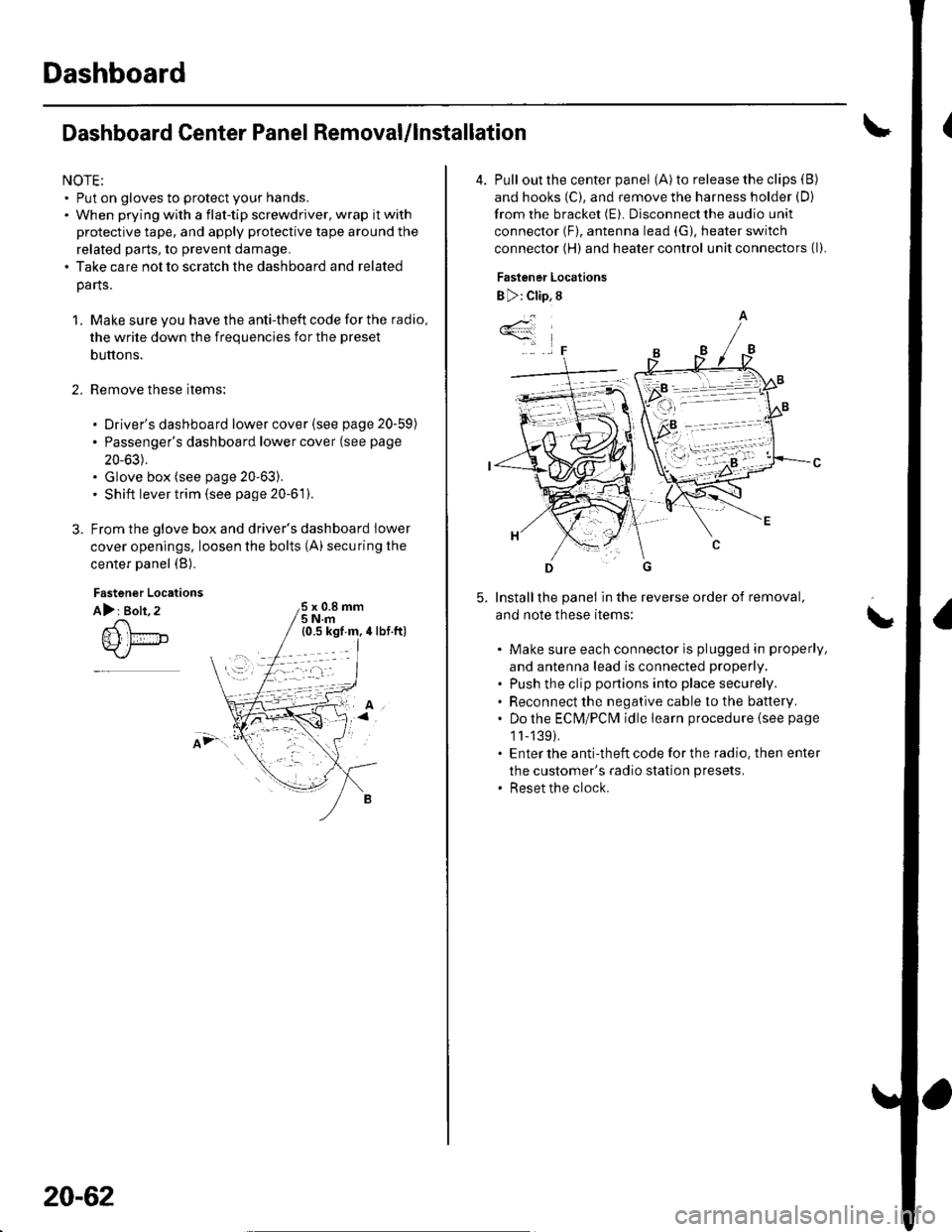
cover openings, loosen the bolts (A) securing the
center panel (B).
2.
Fastener Locations
A): Bolt, 2x 0.8 mm5Nm
;.'
20-62
4. Pull out the center panel (A) to release the clips (B)
and hooks (C), and remove the harness holder (D)
from the bracket (E). Disconnect the audio unit
connector (F), antenna lead (G), heater switch
connector (H) and heater control unit connectors (l).
Fastener Locations
B ): Clip, 8
Installthe panel in the reverse order of removal,
and note these items:
Make sure each connector is plugged in properly,
and antenna lead is connected properly.
Push the clip portions into place securely.
Reconnect the negative cable to the battery.
Do the ECN4/PCt\4 idle learn procedure {see page
1l-139).
Enter the anti-theft code for the radio. then enter
the customer's radio station presets.
Reset the clock.
*4
,F
\
Page 720 of 1139
Dashboard
Dashboard Removal/lnstallation
SRS components are located in this area. Review the
SRS component locations (see page 23-13) and the
precautions and procedures (see page 23-14) in the SRS
section before performing repairs or service.
NOTE:. When prying with a flat-tip screwdriver, wrap it with
protective tape, and apply protective tape around the
related parts to prevent damage.. Have an assistant help you when removing and
installing the dashboa rd.. Take care not to scratch the dashboard, body, and
other related parts.
. Put on gloves to protect your hands.
1. Make sure you have the anti-theft code for the radio,
then write down the frequencies for the preset
buttons.
Disconnect the negative cable from the battery, and
wait at least three minutes before beginning work.
Remove these items:
. Driver's dashboard lower cover (see page 20-59). Driver's dashboard under cover (see page 20-60). Passenger's dashboard lower cover (see page
20-63). Glove box (see page 20-63). Consoles, front and rear (see page 20-57). Shift lever trim {see page 20-61). Center panel (see page 20-62). Kick panels, both sides (see page 20-50). A-pillar trim. both sides (see page 20-50). Steering column (see page 17-9)
20-66
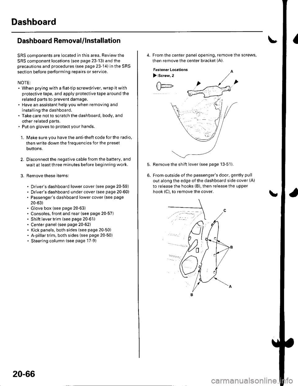
4. From the center panel opening, remove the screws,
then remove the center bracket (A).
Fastener Locations
):Screw,2
Remove the sh ift lever (see page 13-51).
From outside of the passenger's door, gently pull
out along the edge of the dashboard side cover (A)
to release the hooks (B), then release the upper
hook (C), to remove the cover.
Page 810 of 1139
Dust and Pollen Filter Replacement
The dust and pollen filters should be replaced every
30,000 miles (48.000 km) or 24 months whichever
comes first. Replace the filters more often if the air flow
is less than usual.
1. Open the glove box. Remove both glove box stops,
then let the glove box hang down (see page 20 63).
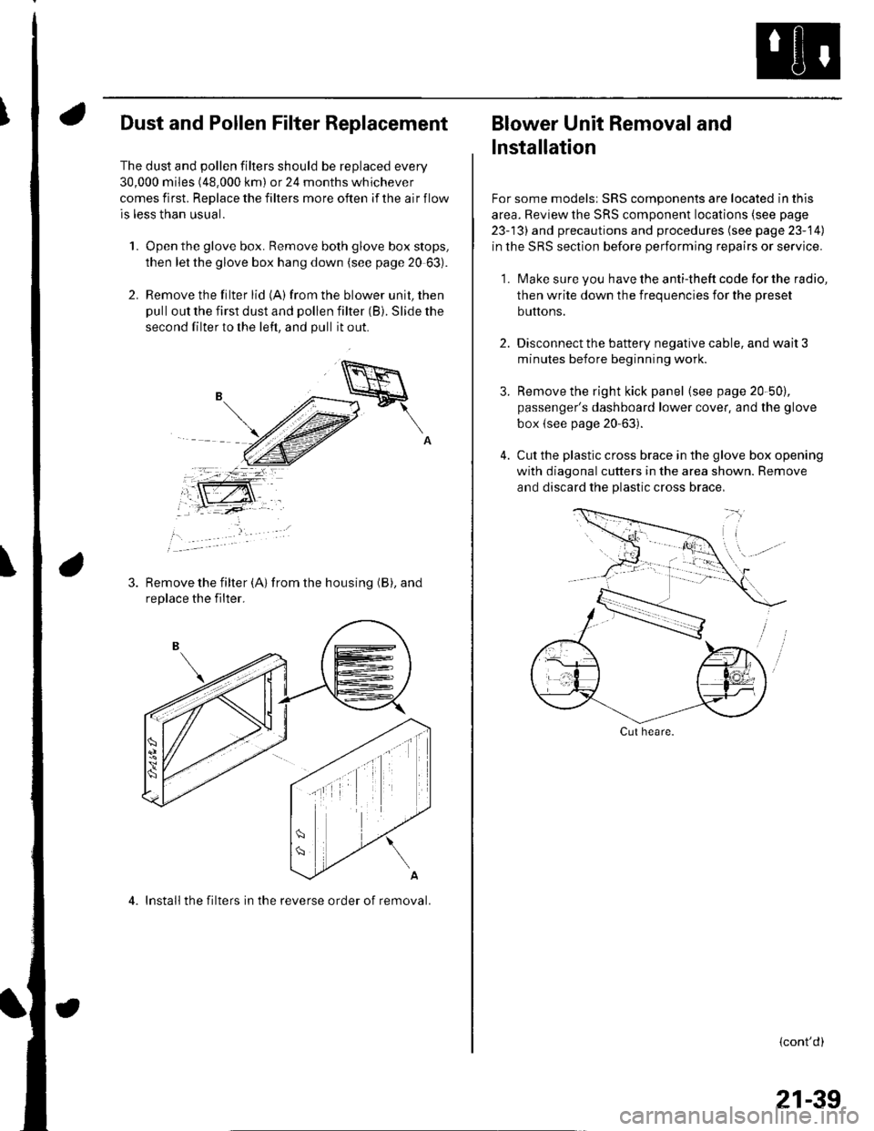
2. Remove the filter lid (A)from the blower unit, then
pull out the first dust and pollen filter (B). Slide the
second filter to the left, and pull it out.
Remove the filter {A) from the housing (B), and
replace the filter.
4. Install the filters in the reverse order of removal.
Blower Unit Removal and
lnstallation
For some models: SRS components are located in this
area. Review the SRS component locations (see page
23-13) and precautions and procedures (see page 23-14)
in the SRS section before performing repairs or service.
1. Make sure you have the anti-theft code for the radio,
then write down the frequencies for the preset
buttons.
2. Disconnect the battery negative cable, and wait 3
minutes before beginning worK.
3. Remove the right kick panel (see page 20-50),
passenger's dashboard lower cover, and the glove
box {see page 20-63).
4. Cut the plastic cross brace in the glove box opening
with diagonal cutters in the area shown. Remove
and discard the plastic cross brace,
Cut heare.
{cont'd)
21-39