service HONDA CIVIC 2002 7.G Workshop Manual
[x] Cancel search | Manufacturer: HONDA, Model Year: 2002, Model line: CIVIC, Model: HONDA CIVIC 2002 7.GPages: 1139, PDF Size: 28.19 MB
Page 2 of 1139
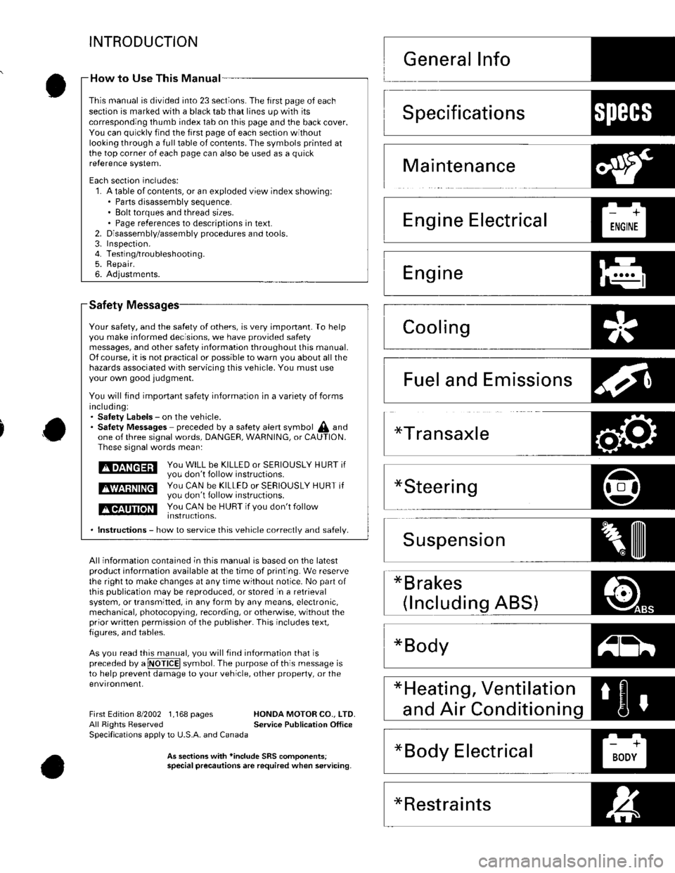
INTRODUCTION
Safety
Your safety, and the satety of others, is very important. To helpyou make informed decisions, we have provided safetymessages, and other safety information throughout this manual.Of course, it is not practical or possible to warn you about all thehazards associated with servicing this vehicle. You must useyour own good judgment.
You will find impoftant safety information in a variety of formsincluding:. Satety Labels - on the vehicle.. Satetv Messages preceded by a salety alert symbol A andone of three signal words, DANGEF, WARNING, or CAUTION.These signal words mean:
tmEnEEril y;,: H,ll i": 5* i5"?;r s E R I o u s LY H u Br ir
E$EEEE ys,: f#,ff ,:hl:3,:JjERrousLY HURT ir
tlGtltT]llilll You cAN b€ HUBT if vou don't follow
. lnstructions - how to service this vehicle correctlv and safelv.
All information contained in this manual is based on the latestproduct information available at the time of printing. We reservethe right to make changes at any time without notice. No part ofthis Oublication maV be reDrodLrced, or stored in a retrievalsystem, or transmitted, in any form by any means, electronic,mechanical, photocopying, recording, or otherwise, without theprior written permission o{ the publisher. This includes text,figures, and tables-
As vou read this manual, vou will tind information that ispreceded by a @ symbol. The purpose of this message isto help prevent damage to your vehicle, other property, or theenvironment,
*Bodyz-tl!^t l
First Edition 8/2002 1,168 pages HONDA MOTOR CO.. LTD.All Rights Reserved Service Publication OfficeSpecifications apply to U.S.A. and Canada
As seclion3 with *inclode SRS comoonentsispecial precautionsare required when servicing.
How to Use This Manual -
This manual is divided into 23 sections. The first page of eachseclion is marked with a black tab that lines up with itscorresponding thumb index tab on this page and the back cover.You can quickly find the first page of each section withoutlooking through a full table of contents. The symbols printed atthe top corner of each page can also be used as a quickre{erence system.
Each section includes:1. A table of contents, or an exploded view index showingl. Parts disassembly sequence.. Bolt torques and thread sizes.. Page references to descriptions in text.Disassembly/assembly procedures and tools.Inspefiron.Testing/troubleshootin g.Repair.Adjustments.
2.3.4.5.6.
Specifications1)ll:{l+'
Maintenance
Emissions
*Restraints
Page 8 of 1139
General Information
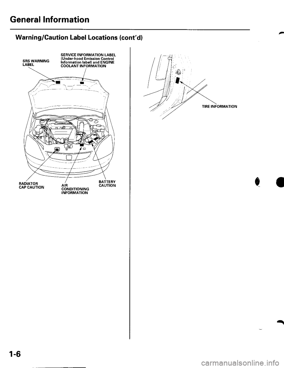
Warning/Caution Label Locations (cont'dl
SRS WARNINGLABEL
SERVICE INFORMATION LABEL(Undor-hood Emission ControlInformation lab€l) and ENGINECOOLANT INFORMATION
RADIATORCAP CAUTION
BATTERYCAUTION
1-6
t
TIRE INFORMATION
c
Page 11 of 1139
Towing
lf the vehicle needs to be towed, call a professional
towing service. Never tow the vehicle behind another
vehicle with just a rope or chain. lt is very dangerous.
Emergency Towing
There are three popular methods of towing a vehicle.
Flat-bed Equipment The operator loads the vehicle
on the back of a truck. This is the best way of
transporting the vehicle.
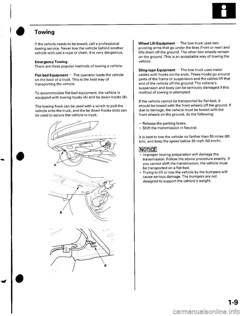
To accommodate flat-bed equipment. the vehicle is
equipped with towing hooks (A)and tie down hooks {B).
The towing hook can be used with a winch to pull the
vehicle onto the truck, and the tie down hooks slots can
be used to secure the vehicle to truck.
1-9
Wheel Lift Equipment The tow truck uses two
pivoting arms that go under the tires (front or rear) and
lifts them off the ground. The other two wheels remain
on the ground. This is an acceptable way of towing the
vehicle.
Sling-type Equipment The tow truck uses metal
cables with hooks on the ends. These hooks go around
parts of the frame or suspension and the cables lift that
end of the vehicle off the ground. The vehicle's
suspension and body can be seriously damaged if this
method of towing is attemPted.
lf the vehicle cannot be transported by flat-bed, it
should be towed with the front wheels off the ground lf
due to damage, the vehicle must be towed with the
front wheels on the ground, do the following:
. Release the parking brake.. shift the transmission in Neutral.
It is best to tow the vehicle no farther than 50 miles (80
km), and keep the speed below 35 mph (55 km/h).
. lmproper towing preparation will damage the
transmission. Follow the above procedure exactly. lf
you cannot shift the transmission, the vehicle must
be transDorted on a flat-bed.. Trying to lift or tow the vehicle by the bumpers will
cause serious damage, The bumpers are not
designed to support the vehicle's weight.
Page 14 of 1139
ne
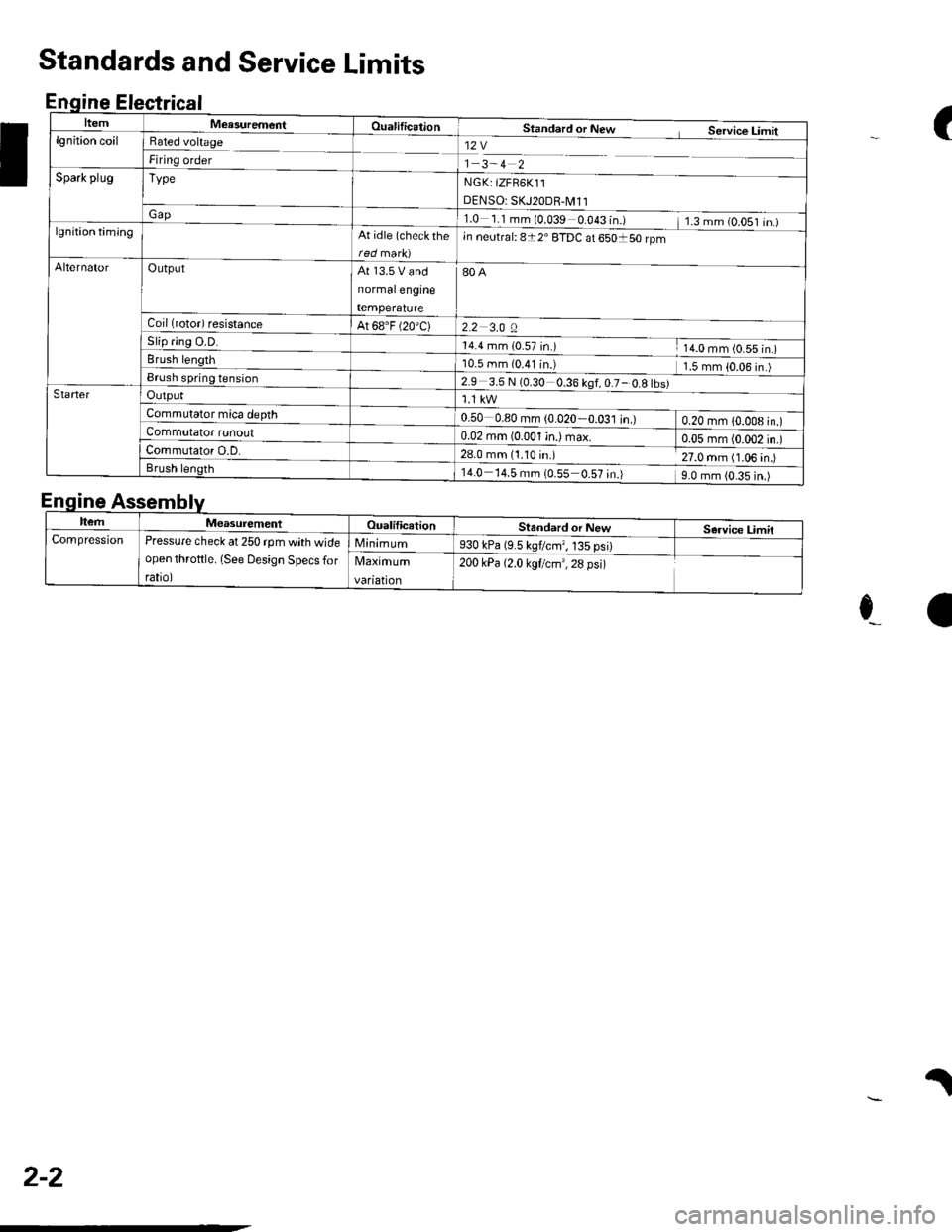
ItemMeasurementOualificationStandard or New Service Limitlgnition coilRated voltage
Firing order12V
1 3-4 2
NGK: tZFB6K11
DENSO: SKJ20DR-M11
1.0 1.1mm(0.039 0.043 in.) 1.3mm(O.OS1 in.)
Spark plugType
Gap
lgnition timingAt idle (check rhein neutral: 8t2' ETDC at 650150 rpm
AlternatorOutputAt 13.5 V and
normalengine
temperature
80A
2.2 3.0 ACoil lrotor) resistanceAt 68.F (20'C)
5|lp flng u.u.14.4 mm {0_57 in.) 14.0 mm (0.55 in.)Brush length10.5 mm (0.41 in.l 1.5 mm {0.06 in.)Brush spring tension2.9 3.5 N (0.30 0.36 kgf,0.7-0.8 tbs)StarterOutput
Commutator mica depth0.50 0.80 mm (0.020-0.031 in.) 0.20 mm 1O.OO8 in.)Commutator tunouto:BlalqryL4i) max o.o5 mm (0.002 in.)Commutator O.D.28.0 mm (1.10 in.) 27.0 mm (1.06 in.)Brush length14.0 14.5 mm {0.55 0.57 in.) 9.0 mm {0.35 in.)
(
I
Standards and Service Limits
Enqine Electrical
E
e_a
.l
nqtne
ItemMeasurementOualificationStandard or NewService LimitCompressionPressure check at 250 rpm with wide
open throftle. (See Design Specs for
rato,
Minimum930 kPa (9.5 kgflcmr, 135 psi)
Maximum
vanatton
200 kPa {2.0 kgf/cm',28 psi)
2-2
Page 15 of 1139
L
vlo
2-3
a
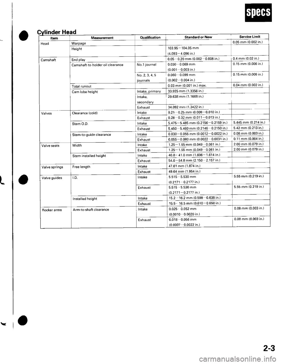
ead
o
nder H
ItemMeasur6mentOualificationStandard or NewService Limit
HeadWarpage0.05 mm {0.002 in.)
Height'103.95 104.05 mm
(4.093 4.096 in.)
CamshaftEnd play0.05 0.20 mm (0.002 0.008 in.)0.4 mm (0.02 in.)
Camshaft to holder oil clearanceNo.l journal0.030 0.069 mm
{0.001 0.003 in.)
0.15 mm {0.006 in.)
No.2,3, 4,5
journals
0.060 0.099 mm
(0.002- 0.004 in.)
0.15 mm (0.006 in.)
Total runout0.03 mrn (0.001 in.) max.0.04 mm {0.002 in.)
Cam lobe heightIntake, primary33.925 mm (1.3356 in.)
Intake,29.638 mm (l.1668 in.)
Exhaust34.092 mm (1.3422 in.)
clearance (cold)lntake0.21 0.2s mm 10.008 0.010 in.)
Exhaust0.28 0.32 mm (0.011 0.013 in.)
Stem O.D-lnlaKe5.475 5.485 mm 10.2156 0.2159 in.)5.445 mm (0.214 in.)
Exhaust5.450 5.460 mm (0.2146 0.2150 in )5.42 mm (0.213 in.)
Stem-to-gLride clearancelntake0.030 0.055 mm (0.0012 0.0022in.|0.08 mm (0.003 in.)
Exhaust0.055 0.080 mm (0.0022 0.0031 in )0.11 mm (0.004 in.)
lntake1.25 1.55 mm (0.049 0.061 in.)2.00 mm {0.079 in.)
Exhaust1.25 1.55 mm (0.049 0.061 in.)2.00 mm {0.079 in.)
stem installed heightlntake40.8- 41.0 mm (1.606 1.614in.)
Exhaust54.6 54.8 mm (2.150 2.157 in.)
Valve springsFree lengthlntake47.61 mm (1.874 in.)
Exhaust49.64 mm (1.954 in.)
Valve guidesLD.Intake5.515 5.530 mm
|.0.2171 0.2117 4n.1
5.55 mm (0.219 in.)
Exhaust5.515 5.530 mm
\0.2111 0.2177 in.l
5.55 mm {0.219 in.)
Installed heightlntaKe15.2 "16.2 mm (0.598 0.638in.)
Exhaust15.5 16.5 mm (0.610 0.650 in.)
Rocker armsArm-to-shaft clearancelntaKe0.025 0.052 mm
(0.00'10 0.0020 in.)
0.08 mm (0.003 in.)
Exhaust0.018 0.056 mm
(0.0007 0.0022 in.)
0.08 mm (0.003 in.)
Page 16 of 1139
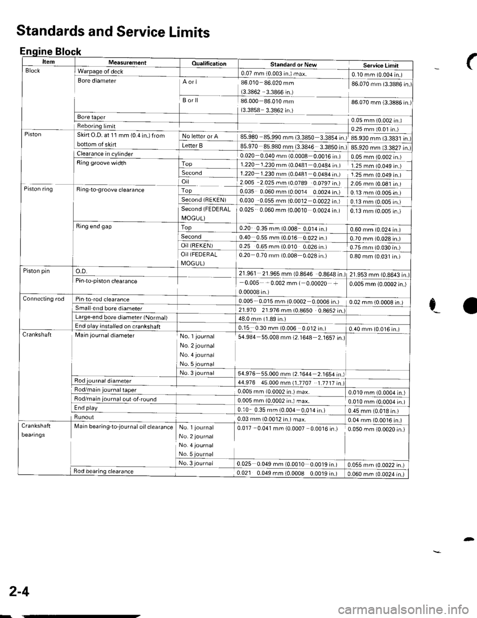
nqtne
ItemMeasurementOualificationStandard or NewService LimirBlock
Piston
I Warpage of deck0.07 mm (0.003 in.) max.foro.. (ulur^^-"1tsore diameterAori
Borll
(3.3858 3.3862 in.)
85.980 85.990 mm (3.3850 3.3854 in.)
l-il?0 €s.980 r"i33846
86.010 86.020 mm
(3.3862 3.3866 in.)
86.000 86.010 mm
86.070 mm (3.3886 in.)
86.070 mm (3.3886 in.)
0.05 mm (0.002 In.J
85.920 mm (3.3827 in.)
0.25 mm (0 0l in.)
85.930 mm (3.383'l in.)
Reboring lrmit
Skirt O.D. at 11 mm (0.4 in.) from
bottom of skirtF" btt"' "' A
Letter B
0.020 0.040 mm (0 0008 0.0016 in.)0.05 mm {0.002 in.)Top1.220 1.230 mm (0.0481 0.0484 in.)1.25 mm 10.049 rn )Second1.220 1.230 mm (0.0481 0 0a84In.)1.25 mm 10.049 in.)
Piston ring
lFis,.€-"'"
",";"*
L-Ring end gap
o.D.
i 2.005 2.025 mm (0.0789 0.0797 in.)
fo.o:s o.oto.rn lo.oora o.ooza i.'.f
EO3t 0 056 rn. {OJ01r OOO2 i")
?.09rrl9.091lt )
0.13 mm (0.005 in )
0.13 mm (0.005 in.)Second (FEDEHAL
I\4OGUL)
Top
0.025 0.060 mm (0.0010 0.0024 in.)0.13 mm (0.005 in )
0.20 0.35 mm (0.008 0.014 in.)0.60 mm (0.024 in.)Second0.40 0.55 mm {0.016 0.022 in.)0.70 mm (0.028 in.)OiI (REKEN)
21.961 21.965 mm {0.8646 0.8648 in.)
0.25 0.65 mm (0.010 0.026 in.)
0 20 0.70 mm i0.008 0.028 in.)
0.75 mm (0.030 in.)OiI(FEDERAL
I\4OG U L)0.80 mm 10.031 in.)
Piston pin21.953 mm l0 8643 inPin'to-piston clearance0.005-*0.002 mm ( 0.00020 +
0.00008 in.)
0.005 mm (0.0002 in.)
Connecting rodPin to-rod clearance0.005 0.015 mm (0.0002 0.0006 in.)0.02 mm lO 0OO8 in ISmall end bore diameler21.970 21.976 mm (0.8650 0.8652 in.)Large-end bore diameter (Normal)48.0 mm (1.89 in.)End play inslalled on crankshaft0.15 0.30 mm (0.006 0.012 in.)0.40 mm (0.016 in.)CrankshaftMain journal diameter
Rod journal diameter
No. l journal
No. 2 journal
No. 4 journal
No. 5 journal
No. 3 journal
s4.e84 s5.008 mm (2.1648=16illl
54.976 55.000 mm (2.1644 2-1654in)
44.976 45.000 mm (1.1707 1.1717 in.lRod/main0.005 mm 10.0002 in.) max.0.010 mm (0.0004 in.)Rod/main iournal out of,round0.005 mm (0.0002 in.) max.0.010 mm (0.0004 in.)End play0.10 0.35 mm (0.004 0.0'14 in.)0.45 mm 10.018 in.)Runout..-'.:�--'+0.03 mm (0.0012 in.) max.0.04 mm {0.0016 in.)
Deaflngs
Marn oear,n9-toJournat ott ctearanceNo. l journal
No. 2 journal
No. 4 journal
No.5
No. 3 journa/
0.017 0.041 mm (0.0007 0.0016 in.)
q0rr034, -rn {O'o010 0-o01r|"tl
0.050 mm (0.0020 in.)
0.055 mm (0.0022 in.)Bod bearing clearance0.021 0.049 mm (0.0008 0.0019 in.)0.060 mm (0.0024 in.)
Standards and Service Limits
Enqine Block
_f
c_a
2-4
-
Page 17 of 1139
L
v
2-5
oi
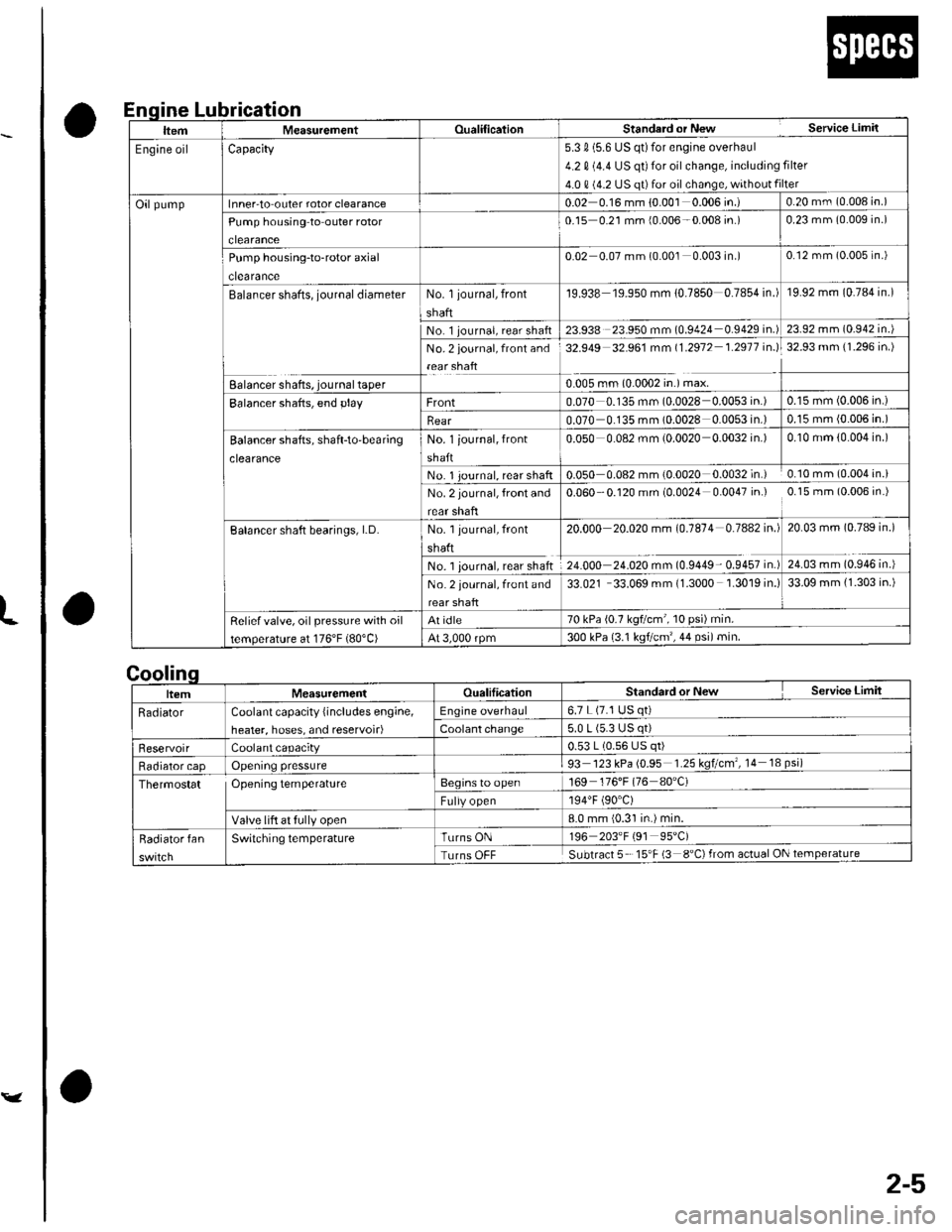
Lubrication
a
a
nqlne
|temMeasurementOualificalionStanderd or New Service Limil
Engine oilCapacity5.3 0 (5.6 US qt)for engine overhaul
4.2 0 (4.4 US qt) for oil change, including filter
4.0 0 (4.2 US qt)for oil change, without filter
Oilpumplnner-to outer rotor clearance0.02 0.16 mm {0.001 0.006 in.)0.20 mm (0.008 in.)
Pump housing to outer rotor
clearance
0-15 0.21 mm {0.006-0.008 in.)0.23 mm (0.009 in.)
Pump housing-to-rotor axial
clearance
0.02 0.07 mm (0.001 0.003 in.)0.12 mm (0.005 in.)
Balancer shafts, journal diameterNo. 1 journal, front
shaft
19.938 19.950 mm 10.7850 0.7854 in.)19.92 mm (0.784 in.)
No 1 journal, rear shaft23.938 23.950 mm (0.9424 0.9429 in.)23.92 mm (0.942 in.)
No. 2 journal, front and
rear shaft
32.949 32.961 mm 11.2912 1.2911 in.l32.93 mm (1.296 in.)
Ealancer shafts, journal taper0.005 rnm (0.0002 in.) max.
Balancer shafts, end playFront0.070 0.135 mm (0.0028 0.0053 in.)0.15 mm (0.006 in.)
Rear0.070 0.135 mm (0.0028 0.0053 in.)0.15 mm (0.006 in.)
Balancer shatts, shaft-to'bear;ng
clearance
No. 1 iournal, front
shaft
0.050 0.082 mm (0.0020 0.0032 in.)0.10 mm (0.004 in.)
No. 1 Journal, rear shaft0.050 0.082 mm (0.0020 0.0032 in.) 0.10 mm (0.004 in.i
No. 2 journal, front and
rear shafl
0.060 -0.120 mm (0.0024 0.0047 in.) 0.15 mm (0.006 in.)
Balancer shaft bearings, LD.No. 1 journal, front
shaft
No. 1 iournal, rear shaft
20.000 20.020 mm (0.1814 0.7442 in.l
Z+.OOO ZI.OZO m- tOSa+e- OSa57 ir'.)
20.03 mm (0.789 in.)
24.03 mm (0.946 in.)
No. 2 journal, front and
rear shaft
33.021 33.069 mm (1.3000 1.3019 in.)33.09 mm {1.303 in.)
Reliefvalve, oil pressure with oil
temperature at 176'F (80"C)
At idle70 kPa (0.7 kq?cm , 10 psr) min.
At 3,000 rpm300 kPa {3.1 ksf/cm',44 psi)min.
Standard or New Service Limit
6.7 L (7.1 USCoolant capacity {includes engine,
heater, hoses, and reservoir)
0.53 L (0.56 US
93 123 kPa (0.95 1.25 kqtcm , 14 18 psi)'t69 176'F (76 80'C)Thermostat OPeningtemPerature
8.0 mm {0.31 in.) min.
Turns OFF Subtract 5 15'F (3 8"C)from actual ON
Page 18 of 1139
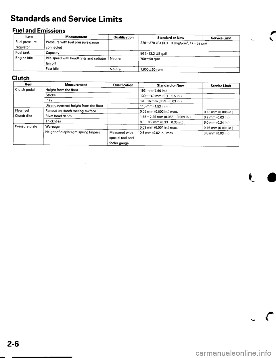
ItemMeasulementOualificationStandard or New Service LimitFuel pressure
regulator
Pressure with fuel pressure gauge
connected
320-370 kPa 13.3-'3.8 kgtcm', 47 52psi)
FueltankCapacity50 4 (13.2 US galiEngine idleldle speed with headlights and radiator
fan off
Neutral750 50 rpm
Fast idleNeutral1,600150 rpm
Standards and Service Limits
Fuel and Emissionsf
.\
ra
Clutch
ItemMea3urem€nlOualificationSlandard or NewService LimitClutch pedalHeight from the floor193 mm (7.60 in.)Stroke130 140 mm 15.1 5.5in.)
10 16 mm (0.39 0.63 in.)Disengagement height from the floor1'15 mm (4.53 in.) min.Bunout on clutch mating surface0.05 mm 10.002 in.) max.0.15 mm (0.006 in.)Clutch discBivet head depth1.65 2.25 mm (0.065 0.089 in.)0.7 mm {0.03 in.)Ihickness8.3 8.9 mm (0.33 0.35 in.)6.0 mm (0.24 in.)Pressure plateWarpage0.03 mm (0.001 in.)max.0.15 mm (0.001 in.)Height of diaphragm spring fingersMeasured with
specialtool and
feeler gauge
0.6 mm (0.02 in.) max.0.8 mm (0-03 in.)
2-6
\
Page 20 of 1139
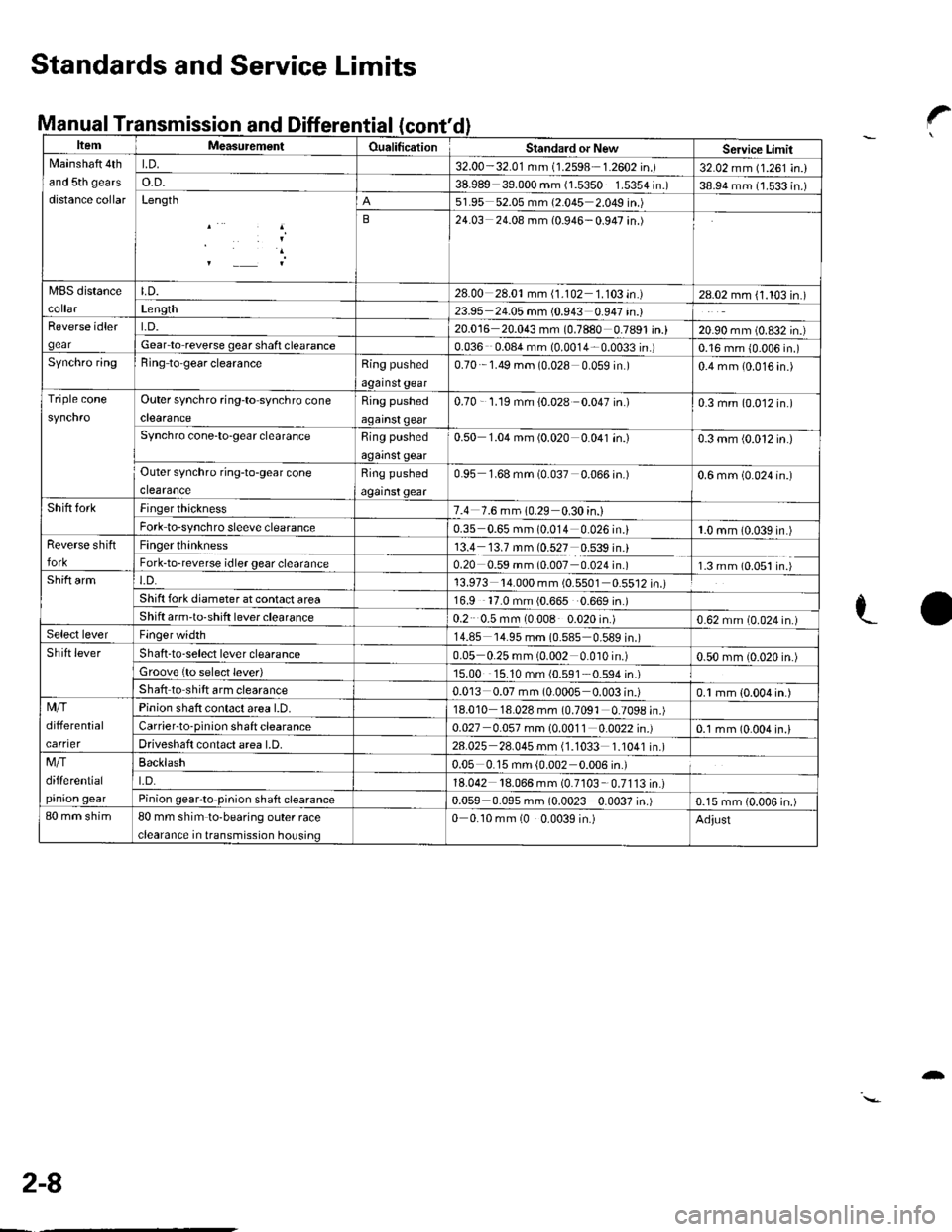
anuat I ransmcont'
ItemMeasutemenlOualificationStandard or NewServicc LimitNlainshaft 4th
and 5th gears
distance collar
LD.32.00-32.01 mm (1.2598 1.2602 in.)32.02 mm (1.261 in.)o.D.38.989 39.000 mm (1.5350 1.5354 in.)38.94 mm (1.533 in.)Length51.95 52.05 mm (2.045 2.049 in.)
B24.03 24.08 mm (0.946-0.947 in.)
MBS distanceLD.28.00 28.01mm (1.102 1.103 in.)28.02 mm (1.103 in.)Len9th23.95 24.05 mm (0.943 0.947 in.)Reverse idler
gear
t.D.20.016 20.043 mm (0.7880 0.7891 in.)20.90 mm (0.832 in.)Gear lo reverse gear shafi clearance0.036 0.08a mm (0.0014 0.0033 in.)0.16 mm {0.006 in.)Synchro ringBing to'gear clearanceRing pushed
against gear
0.70 1.49 mm (0.028 0 059 in )0.4 mm (0.016 4n.)
Triple coneOuter synchro ring-to synchro cone
clearance
Ring pushed
against qear
0.70 - '1.19 mm {0.028 0.047 in.)0.3 mm (0.012 in.)
Synchro cone-to-gear clearanceRing pushed
against gear
0.50 1.04 mm (0.020 0.041 in.)0.3 mm (0.012 in.)
Outer synchro ring-to-gear cone
clearance
Ring pushed
against gear
0.95 1.68 mm (0.037 0.066 in.)0.6 mm (0.024 in.)
Shift forkFinger thickness7.4 7.6 mm 10.29 0.30 in.)Fork to-synchro sleeve clearance0.35 0.65 mm (0.014 0.026 in.i1.0 mm (0.039 in.)Reverse shift
fork
Finger thinkness13.4 13.7 mm (0.527 0.539 in.)Fork-to-reverse idler gear clearance0.20 0.59 mm (0.007 0.024 in.)1.3 mm (0.051 in.)Shift armt.D.13.973 '14.000 mm (0.5501 0.5512 in.)Shift fork diameter at conlact area16.9 '17.0 mm (0.665 0.669 in.)Shift arm'to-shift lever clearance0.2 0.5 mm (0.008 0.020 in.)0.62 mm (0.024 in.)Select leverFinger width14.85 '14.95 mm (0.585 0.589 in.)Shift leverShaft -to-select lever clearance0.05 0.25 mm (0.002 0.010 in.)0.50 mm (0.020 in.)Groove {to select lever)15.00 15.10 mm {0.591 0.594 in.)
Shaft to shift arm clearance0.013 0.07 mm (0.0005 0.003 in.)0.1 mm {0.004 in.)Mfi
differential
carrier
Pinion shaft contact area l.D.18.010 18.028 mm (0.7091 0.7098 in.)Carrier-to-pinion shaft clearance0.027 0.057 mm (0.0011 0.0022 in.)0.1 mm (0.004 in.lDriveshaft contact area LD.28.025 28.045 mm (1.1033 1.1041 in.)Mfi
differential
pinion qear
Backlash0.05 0.15 mm {0.002 0.006 in.)
t.D.18.042 18.066 mm (0.7103 0.7113in.)Pinion gearto pinion shaft clearance0.059 0.095 mm (0.0023 0.0037 in.)0.15 mm (0.006 in.)80 mm shim80 mm shim to-bearing outer race
clearance in transmission housing
0 0.10 mm (0 0.0039 in.)Adjust
Standards and Service Limits
Manual Transmission and Differential?
LO
2-8
-
Page 21 of 1139
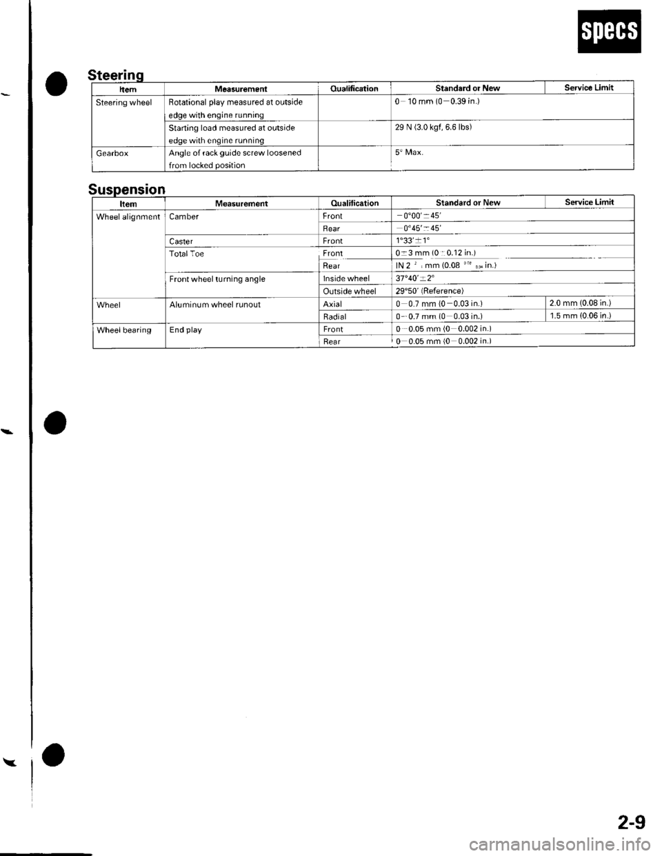
Y
2-9
o
o
a
0 10 mm (0 0.39 in.)Rotational olav measured at outside
29 N (3.0 kgf.6.6lbs)Starting load measured at outside
Angle of rack guide screw loosened
n
ItemMeasurementOualiticationStandard or New Service Limit
WheelalignmentCamberFront0'00' 45'
Rear0'45'- 45
CasterFront1"33'�11"
TotalToelryttRear
0-3 mm (0::0.12 in.)
lN 2 ' , mm (0.08 "' ,, in.)
Frontwheel turning anglelnside wheel37'40'-2'
Outside wheel29'50'(Reference)
Aluminum wheel runoutAxial0 0.7 mm (0 0.03 in.) 2.0 mm (0.08 in.)
Radial0 - 0.7 mm (0 0.03in.) l.5mm{0.06in.)
WheelbearingEnd playFront0 0.05 mm (0 0.002 in.)
Rear0 0.05 mm (0 0.002 in.)