engine coolant HONDA CIVIC 2002 7.G Workshop Manual
[x] Cancel search | Manufacturer: HONDA, Model Year: 2002, Model line: CIVIC, Model: HONDA CIVIC 2002 7.GPages: 1139, PDF Size: 28.19 MB
Page 8 of 1139
General Information
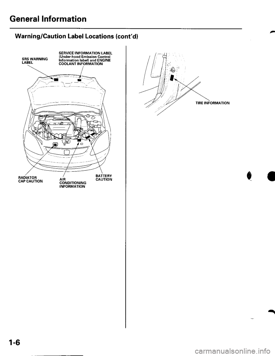
Warning/Caution Label Locations (cont'dl
SRS WARNINGLABEL
SERVICE INFORMATION LABEL(Undor-hood Emission ControlInformation lab€l) and ENGINECOOLANT INFORMATION
RADIATORCAP CAUTION
BATTERYCAUTION
1-6
t
TIRE INFORMATION
c
Page 17 of 1139
L
v
2-5
oi
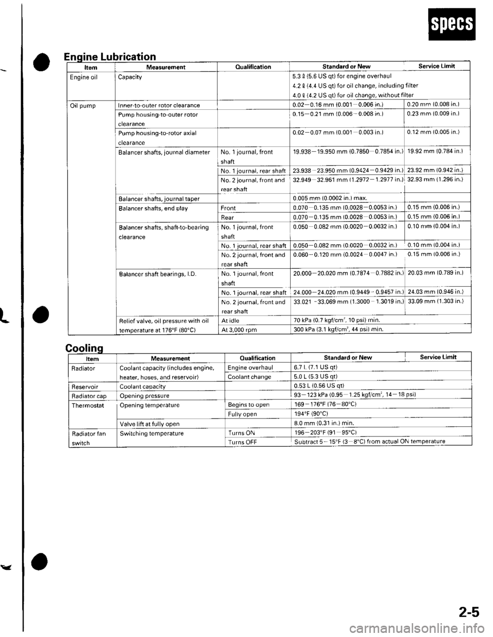
Lubrication
a
a
nqlne
|temMeasurementOualificalionStanderd or New Service Limil
Engine oilCapacity5.3 0 (5.6 US qt)for engine overhaul
4.2 0 (4.4 US qt) for oil change, including filter
4.0 0 (4.2 US qt)for oil change, without filter
Oilpumplnner-to outer rotor clearance0.02 0.16 mm {0.001 0.006 in.)0.20 mm (0.008 in.)
Pump housing to outer rotor
clearance
0-15 0.21 mm {0.006-0.008 in.)0.23 mm (0.009 in.)
Pump housing-to-rotor axial
clearance
0.02 0.07 mm (0.001 0.003 in.)0.12 mm (0.005 in.)
Balancer shafts, journal diameterNo. 1 journal, front
shaft
19.938 19.950 mm 10.7850 0.7854 in.)19.92 mm (0.784 in.)
No 1 journal, rear shaft23.938 23.950 mm (0.9424 0.9429 in.)23.92 mm (0.942 in.)
No. 2 journal, front and
rear shaft
32.949 32.961 mm 11.2912 1.2911 in.l32.93 mm (1.296 in.)
Ealancer shafts, journal taper0.005 rnm (0.0002 in.) max.
Balancer shafts, end playFront0.070 0.135 mm (0.0028 0.0053 in.)0.15 mm (0.006 in.)
Rear0.070 0.135 mm (0.0028 0.0053 in.)0.15 mm (0.006 in.)
Balancer shatts, shaft-to'bear;ng
clearance
No. 1 iournal, front
shaft
0.050 0.082 mm (0.0020 0.0032 in.)0.10 mm (0.004 in.)
No. 1 Journal, rear shaft0.050 0.082 mm (0.0020 0.0032 in.) 0.10 mm (0.004 in.i
No. 2 journal, front and
rear shafl
0.060 -0.120 mm (0.0024 0.0047 in.) 0.15 mm (0.006 in.)
Balancer shaft bearings, LD.No. 1 journal, front
shaft
No. 1 iournal, rear shaft
20.000 20.020 mm (0.1814 0.7442 in.l
Z+.OOO ZI.OZO m- tOSa+e- OSa57 ir'.)
20.03 mm (0.789 in.)
24.03 mm (0.946 in.)
No. 2 journal, front and
rear shaft
33.021 33.069 mm (1.3000 1.3019 in.)33.09 mm {1.303 in.)
Reliefvalve, oil pressure with oil
temperature at 176'F (80"C)
At idle70 kPa (0.7 kq?cm , 10 psr) min.
At 3,000 rpm300 kPa {3.1 ksf/cm',44 psi)min.
Standard or New Service Limit
6.7 L (7.1 USCoolant capacity {includes engine,
heater, hoses, and reservoir)
0.53 L (0.56 US
93 123 kPa (0.95 1.25 kqtcm , 14 18 psi)'t69 176'F (76 80'C)Thermostat OPeningtemPerature
8.0 mm {0.31 in.) min.
Turns OFF Subtract 5 15'F (3 8"C)from actual ON
Page 31 of 1139
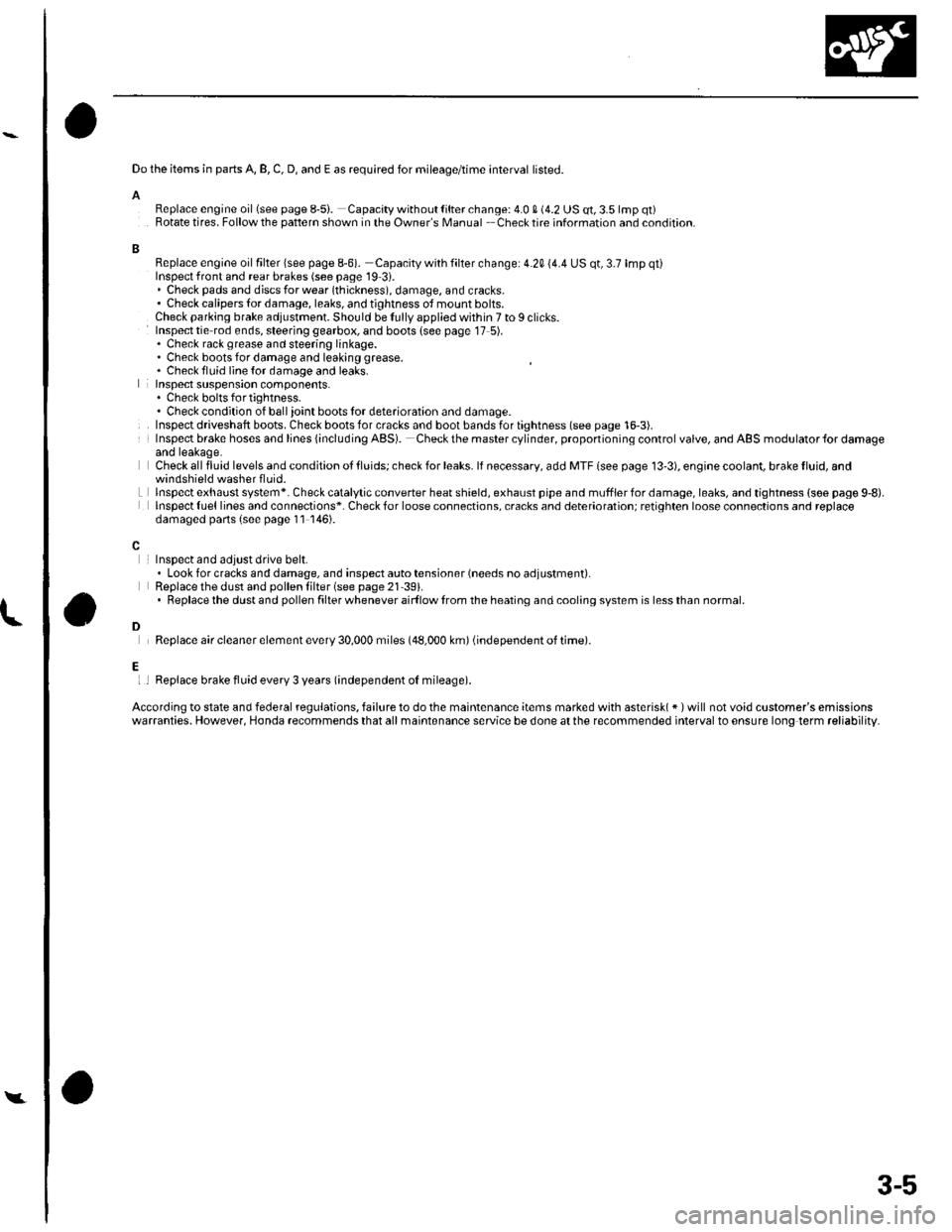
Do the items in parts A, B, C, D, and E as required for mileage/time interval listed.
AReplace engine oillsee page 8-5i. Capacity without lilter change: 4.0 S (4.2 US qt, 3.5 lmp qt)Rotate tires. Follow the pattern shown in the Owner's Manual Checktire information and condition.
BReplace engine oil filter lsee page 8-6). Capacity with filter change: 4.20 (4.4 US qt, 3.7 lmp qt)Inspect front and rear brakes (see page 19 3i.. Check pads and djscs for wear (thickness), damage, and cracks.' Check calipers tor damage, leaks, and tjghtness ot mount bolts.Check parking brake adjustment. Should be Iully applied within 7 to I clicks.Inspect tie rod ends, steering gearbox, and boots {see page 17 5).. Check rack grease and steering linkage.. Check boots for damage and leaking grease. Chack fluid line {or damage and leaks.lnspect suspension components.. Chock bolts fo r tig htness.. Check condition of ball ioint boots lor deterioration and damage.Inspect driveshaft boots. Check boots for cracks and boot bands for tightness (see page 16-3).Insp€ct brake hoses and lines {including ABS). Checkthe mastercylinder, proponioning control valve, and ABS modulator{or damageand leakage.Check all fluid levels and condition ot tluids; check for leaks. lf necessary, add MTF lsee page 13'3), engioe coolant, brake fluid, and
Lwindshield washer fluid.lnspectexhaust system*. Check catalytic converter heatshield, exhaust pipe and mufflerfordamage,leaks, and tightness {soe page 9,8).lnspect {uel lines and connections*. Check for loose connections, cracks and deterioration; retighten loose connoctions and replacedamaged parts (s€e page 11 146).
InsDect and adiust drive belt.. Look for cracks and damage, and inspect auto tensioner (needs no adjustment).Replace the dust and pollen lilter (see page 21 39).. Replacethe dustand pollen filter whenever airf low lrom the heating and cooling system is lessthan normal.
Replace air cleaner element every 30,000 miles (48,000 km) (independent of time).
l
D
Ei I Replace brake fluid every 3 years (independent oI mileage).
According to state and federal regulations, failure to do the maintenance items marked with asterisk( * ) will not void customer's emissionswarranties. However, Honda recommends that all maintsnance service be done at the recommended interval to ensure long term reliability.
Y
3-5
Page 33 of 1139
L
A
I
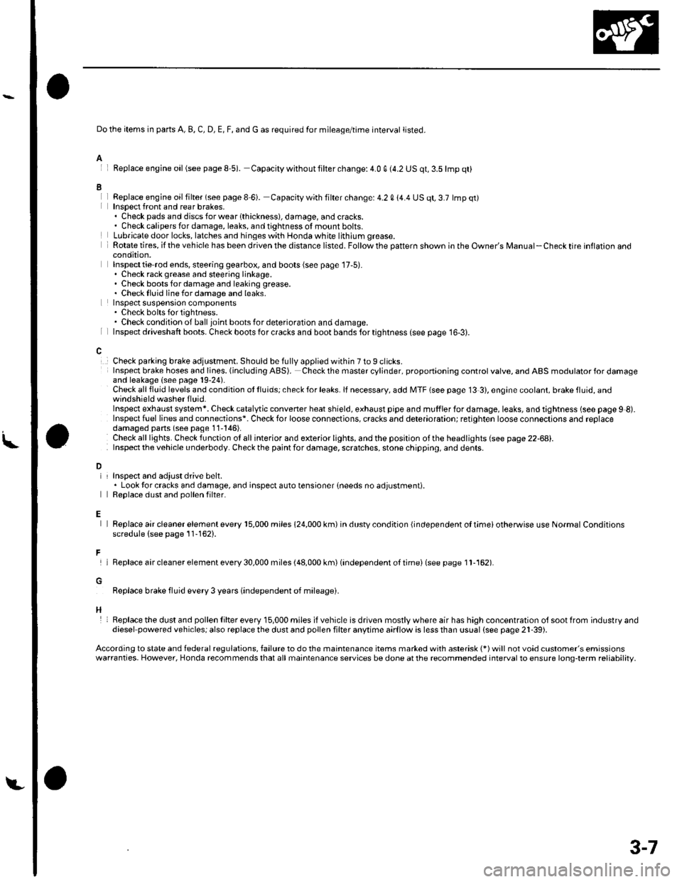
Do the items in parts A, B, C, D, E, F, and G as required for mileage/time interval listed.
Feplace engine oil(see pageS 5). Capacity withoutlilter change:4.0 q (4.2 US qt,3.5lmp qt)
Replace engjne oil filter (see page I 6). Capacity with filter change: 4.2 0 14.4 US qt, 3.7 lmp qt)Insoect front and rear brakes,. Check pads and discsforwearlthickness), damage, andcracks.. Check calipers for damage, leaks, and tightness of mount bolts.Lubricate door locks, latches and hinges with Honda white lithium grease.Rotate tires, if the vehicle has been driven the distance listed. Follow the pattern shown in the Owner's Manual-Check tire inflaron aoocondition,Inspecttie rod ends, steering gearbox, and boots (see page 17,5).. Check rack grease and steering linkage.. Check boots for damage and leaking grease.. Checklluid linefordamage and leaks.Inspect suspensron components. Check bolts for tightness.. Check condition of ball joint boots for deterioration and damage.Inspect driveshaft boots. Check boots for cracks and boot bands for tightness (see page 16-3).
Check parking brake adjustment. Should be fully applied within 7 to 9 clicks.Insp€ct brake hoses and lioes. (including ABS). Check the master cylinder, proportioning control valve, and ABS modulator for damageand leakage (see page 19-24).Check all fluid levels and condition ot lluids; check for leaks. lf necessary, add MTF (see page 13 3), engine coolant, brake fluid, andwindshield washer f luid.Inspect exhaust system*. Check catalytic converter heat shield, exhaust pipe and muffler for damage, leaks, and tightness (see page 9 8).Inspect fuel lines and connections*. Check for loose connections, cracks and deterioration; retighten loose connections and replacedamaged pans (seo page 11'146).Check alllights. Checkfunction otallinterior and exterior lights, andthe position ofthe headlights (see page 22-68).Inspect the v€hicle underbody. Check the paint for damage, scratches, stone chippin0, and dents.
L
D
E
F
H
InsDect and adiust drive belt.. Look tor cracks and damage, and inspect auto tensioner {needs no adjustment).Reolace dust and oollen filter.
Replace air cleaner element every 15,000 miles 124,000 km) in dustv condition {independent ol timei otherwise use Normal Conditionsscredule (see page 11-162).
lReplaceaircleanerelementevery30,000miles(48,000km)(independento{timei(seepagell-162).
Replace brake fluid every 3 years (independent oJ mileagei.
Replacethe dust and pollen Iilter every 15,000 miles ifvehicle is driven mostlywhere air has high concentration olsootfrom industryanddiesel powered vehiclesj also replace the dust and pollen filter anytime aarflow is less than ussal (see pags 21-39).
According to state and federal regulations, failure to do the maintenance items marked with asterisk (*) will not void customer's emissionswarranties. However, Honda recommends that all maintenance services be done at the recommended interval to ensure long-term reliability,
3-7
Page 34 of 1139
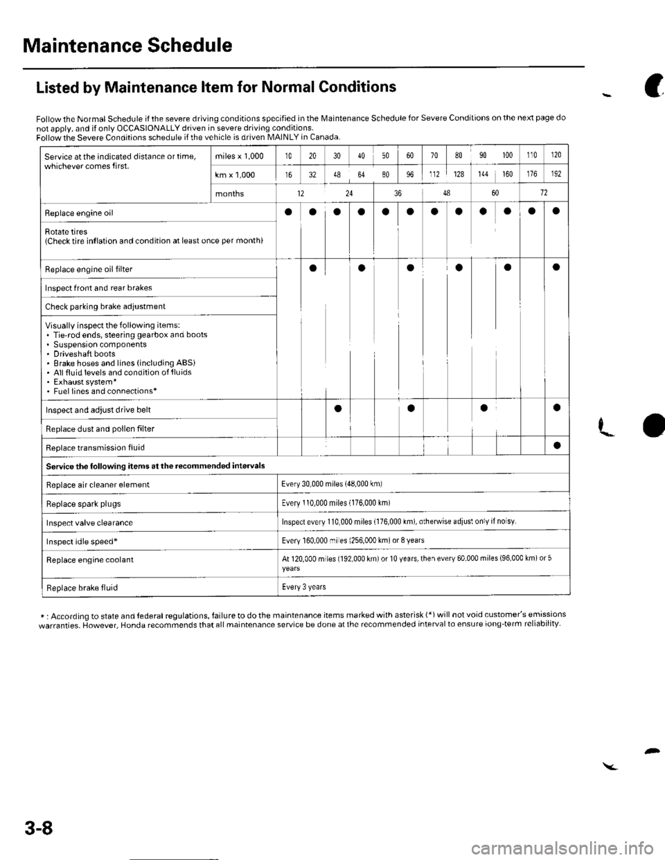
Maintenance Schedule
Service atthe indicated distance ortime,whichever comes first.miles x 1,000t020304050708090 100110r20
km x 1,000163248648096112128144 160192
months12243486012
Replace engine oilooooaooaaoOa
Rotate tires{Check tire intlation and condition at least once per month)
Replace engine oil filterooaaaa
Inspect front and rear brakes
Check parking brake adjustment
Visually inspect the following items:. Tie-rod ends, steering gearbox and boots. Suspension components. Driveshaft boots. Brake hoses and lines (including ABSi. Allfluid levels and condition of{luids. Exhaust system*. Fuel lines and connections*
Inspect and adjust drive beltaaaa
Replace dust and pollen filter
Reolace transmission fluid
Servicethe following items at the recommended intervals
a
Replace air cleaner elementEvery 30,000 miles (48,000 km)
Replace spark plugsEvery 110,000 miles (176,000 Lm)
Inspect valve clearanceInspect every 110,000 miles {176,000 km), otherwise adiusl only if noisy.
Inspect idle speed*Every 160.000 mr es 1256,000 km) or 8 years
Replace engine coolantAt 120,000 miles (192,000 km) or 10 years, then every 60,000 miles (96,000 km) or 5
Replace brake fluidEvery 3 years
Listed by Maintenance ltem for Normal Conditions
Follow the Normal Schedule if the severe driving conditions specified in the lMaintenance Schedule for Severe Conditions on the next page do
not apply, and if only OCCASIONALLY driven in severe driving conditions.Follow the Severe Conditions schedule if the vehicle is driven MAINLY in Canada.
* : According to state and lederal regulations, failure to do the maintenance items marked with asterisk (*) will not void customer's emissions
warranties. However, Honda recommends that all maintenance service be done at the recommended interval to ensure long-term reliability-
c
3-8
Page 35 of 1139
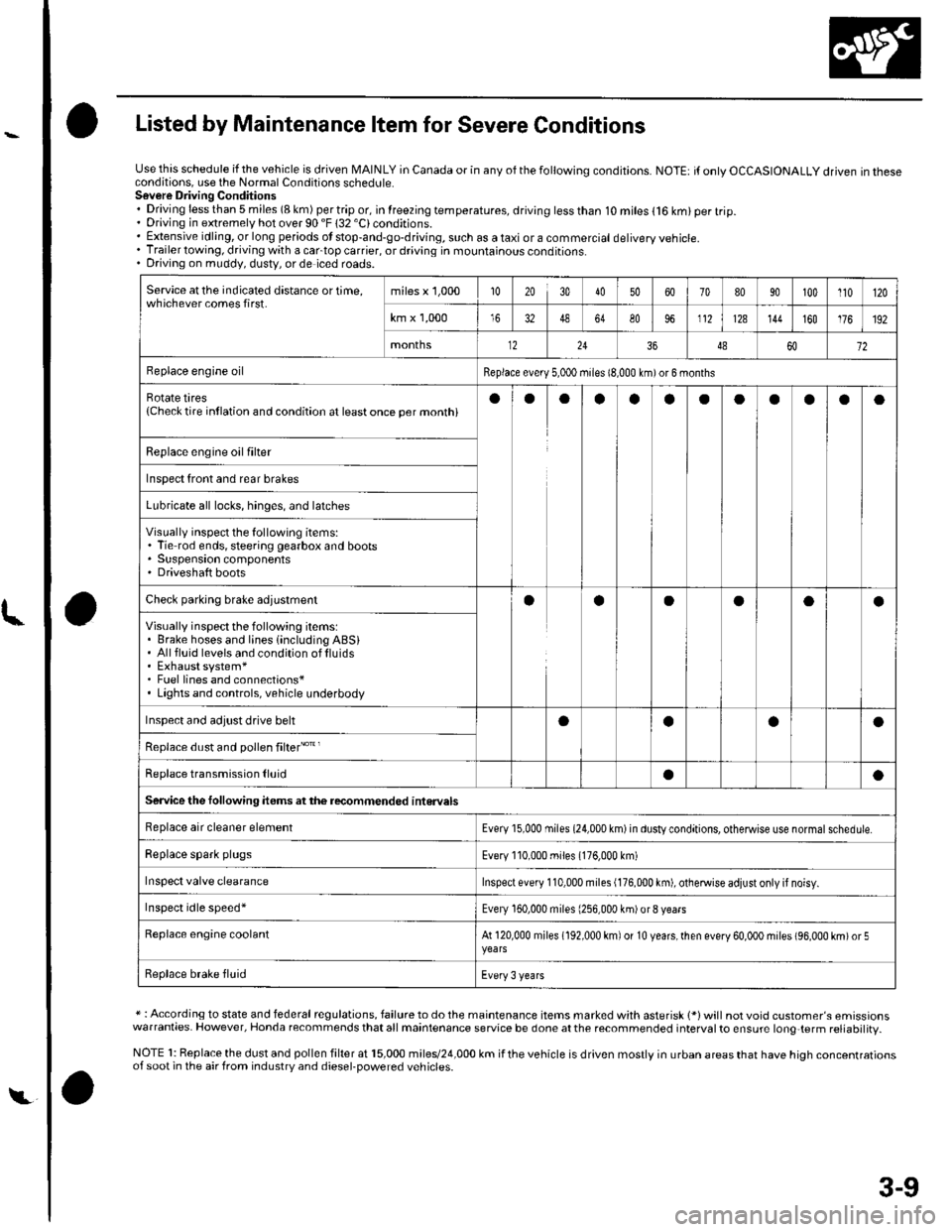
Listed by Maintenance ltem for Severe Conditions
Use this schedule if the vehicle is driven MAINLY in Canada or in anv of the followina conditions.NOTE: it only OCCASIONALLY driven in theseconditions, use the Normal Conditions schedute.Sovere Driving Conditions. Driving less than 5 miles (8 km) per trip or, in lreezing temperatures, driving less than. Driving in extremely hot over 90 "F 132 'C)conditions.10 miles (16 km) per trip.
. Extensive idling, or long periods ot stop-and-go-driving, such as a taxi or a commercial delivery vehicle.. Trailer towing, driving with a cartop carrier, or driving in mountainous conditions.. Driving on muddy, dusty, or de iced roads.
Service at the indicated distance or time,whichever comes first.miles x 1,000102030405060708090100110120
km x 1,0001648648096112128144160176192
months122436486072
Replace engine oilReplace every 5,000 miies 18,000 km)or 6 months
Rotate tires{Checktire intlation and condition at leastonce per monthiaoaaoaaoaaao
Replace engine oil fiher
Inspect front and rear brakes
Lubricate all locks, hinges, and latches
Visually inspect the following items:. Tie rod ends, steering gearbox and boots. Suspension components' Driveshaft boots
Checl parking brale adjuslmentaaOaoa
Visually inspect the following items:. Brake hoses and lines {including ABSi. Allfluid levels and condition oflluids. Exhaust system*. Fuel lines and connections*. Lights and controls, vehicle underbody
Inspect and adjust drive behoaoa
Replace dust and pollen filter"o't'
Replace transmission lluidaa
Service the following items atthe recommended interuals
Replace air cleaner elementEvery 15,000 miies (24,000 km) in dusty conditions, otheMise use normal schedule.
Replace spark plugsEvery 110,000 miles (176,000 km)
Inspect valve clearanceInspect every 110,000 miles (176,000 km), otheMise adiust only if noisy.
Inspect idle speed'Every 160,000 miles (256,000 km)or8 vears
Replace engine coolantAt 120,000 miles (192,000 km) of 10 years,lhen every 60,000 miles (96,000 km)or 5
Replace brake fluidEvery 3 years
* : According to state and federal regulations, failure to do the maintenance items marked with asterisk 1*)will not void customer's emissionswarranties. However, Honda recommends that all maintenance service be done at the recommended interval to ensure long{erm reliabilitv.
NOTE 1: Replace the dust and pollen filter at 15,000 miles/24,000 km if the vehicle is driven mostly in urban areas that have high concentrationsof soot in the air from industrv and diesel-Dowered vehicles.
t,
3-9
Page 85 of 1139
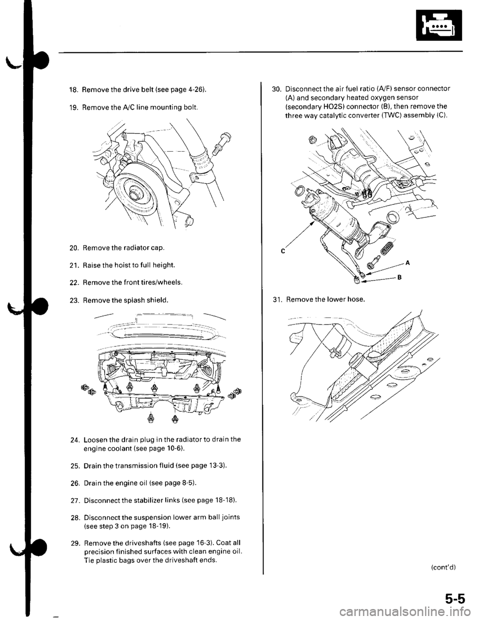
18.
19.
Remove the drive belt (see page 4-26).
Remove the lvC line mounting bolt.
20. Remove the radiator cap.
21. Raise the hoist to full height.
22. Remove the front tires/wheels.
23. Remove the splash shield.
o@
24. Loosen the drain plug in the radiatorto drain the
engine coolant (see page 10-6).
25. Drain the transmission fluid (see page 13'3).
26. Drain the engine oil {see page 8-5).
27. Disconnect the stabilizer links (see page 18-18).
28. Disconnect the suspension lower arm ball joints
(see step 3 on page 18-19).
29. Remove the driveshafts {see page 16-3). Coat all
precision finished surfaces with clean engine oil.
Tie plastic bags over the driveshaft ends.
30. Disconnect the air fuel ratio {4,/F) sensor connector
(A) and secondary heated oxygen sensor
(secondary HO2S) connector (B), then remove the
three way catalytic converter {TWC) assembly {C).
31. Remove the lower hose.
(cont'd)
5-5
Page 88 of 1139
Engine Assembly
Engine Removal (cont'd)
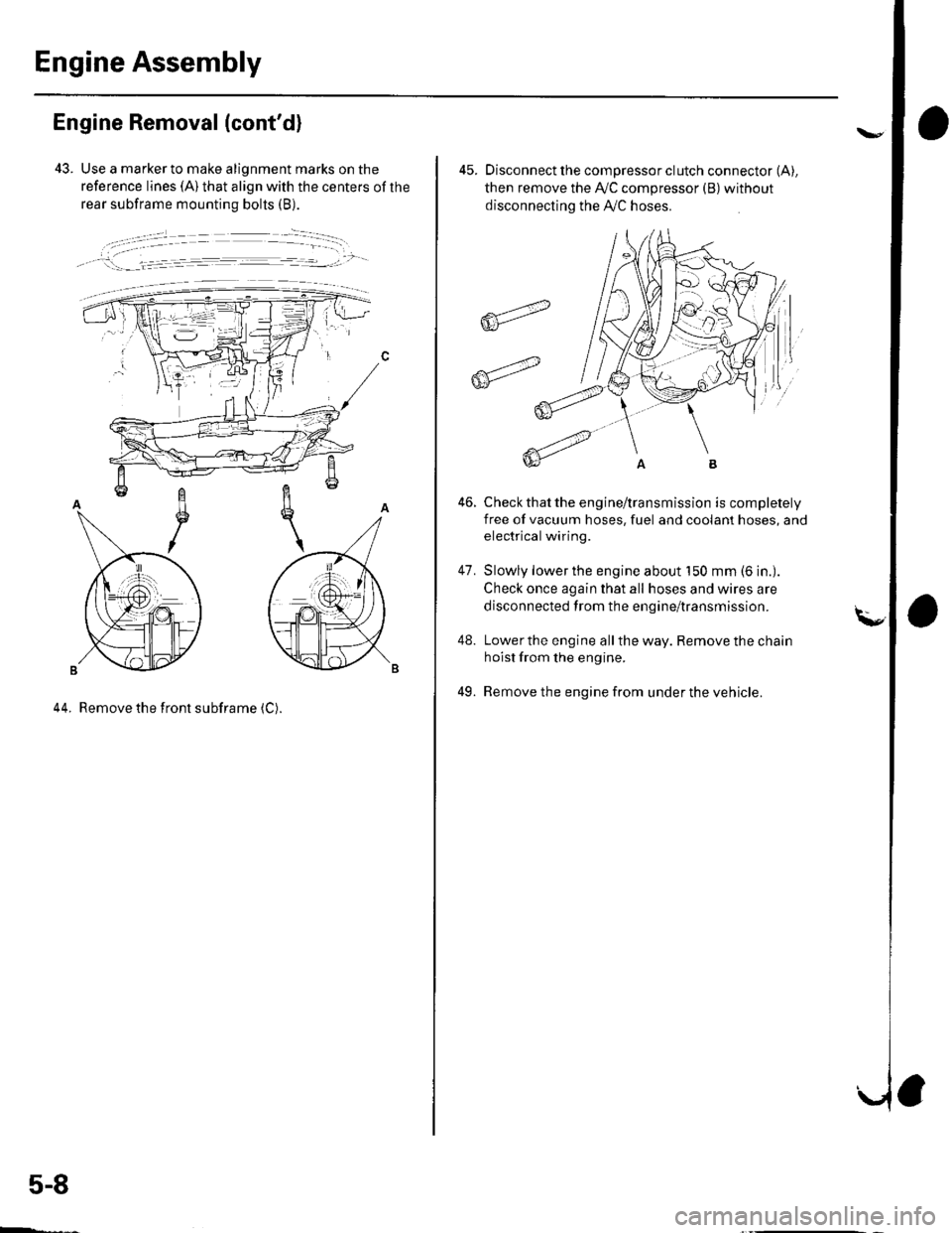
43. Use a marker to make alignment marks on the
reference lines (A) that align with the centers of the
rear subframe mounting bolts (B).
, !:_- _l.= :r -- ---.-','- -
44. Remove the front subframe (C).
5-8
ffi4
ffit'"
45. Disconnect the compressor clutch connector (A),
then remove the Ay'C compressor (B)without
disconnecting the A'./C hoses.
Check that the engine/transmission is completely
free of vacuum hoses, fuel and coolant hoses, and
electrical wiring.
Slowly lower the engine about 150 mm (6 in.).
Check once again that all hoses and wires are
disconnected trom the engine/transmission.
Lower the engine all the way. Remove the chain
hoist from the engine.
Remove the engine from under the vehicle.
46.
47.
48.
49.
Page 95 of 1139
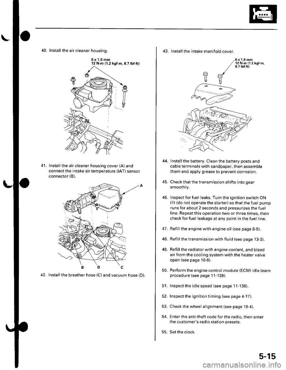
40. Install the air cleaner housinq.
6x1.0mm12 N m (1.2 kgf.m,8.7 lbt.ft)
Install the air cleaner housing cover (A) and
connect the intake air temperature (lAT) sensor
connector (B),
42. Installthe breather hose (C) and vacuum hose 1D).
41.
43. Installthe intake manifold cover.
6x1.0mm12Nm11.2kgf.m.8.7 tbf.ft)
Installthe battery. Clean the battery posts and
cable terminals with sandpaper, then assemble
them and apply grease to prevent corrosion.
Check that the transmission shifts into gear
smoothly.
Inspect for fuel leaks. Turn the ignition switch ON(ll) {do not operate the starter) so that the fuel pump
runs for about 2 seconds and pressurizes the fuel
line. Repeat this operation two or three times, then
check for fuel leakage at any point in the fuel line.
Refillthe engine with engine oil (see page 8-5).
Refill the transmission with fluid (see page 13-3).
Refill the radiator with engine coolant, and bleed
air from the cooling system with the heater valve
open (see page 10-6).
Perform the engine control module (ECM) idle learnprocedure (see page 11-139).
Inspect the idle speed (see page 1 1-138).
Inspect the ignition timing (see page 4-17).
Check the wheel alignment {see page 18-4).
Enter the anti-theft code for the radio, then enter
the customer's radio station presets.
Set the clock.
YE
44.
41.
]tE
46.
48.
49.
52.
53.
54.
50.
51.
55.
5-15
Page 118 of 1139
Gylinder Head Removal
NOTE:. Use fender covers to avoid damaging painted
surfaces.
To avoid damage, unplug the wiring connectors
carefully whlle holding the connector portion.
To avoid damaging the cylinder head, wait until the
engine coolant temperature drops below 100'F (38"C)
betore loosening the cylinder head bolts.
Mark all wiring and hoses to avoid misconnection.
Also, be sure that they do not contact other wiring or
hoses, or interfere with other parts.
'1.
2.
3.
Drain the engine coolant (see page 10-6).
Remove the drive belt (see page 4-26).
Remove the intake manifold {see page 9-3).
Remove the air cleaner housing (see step 7 on page
5-2t.
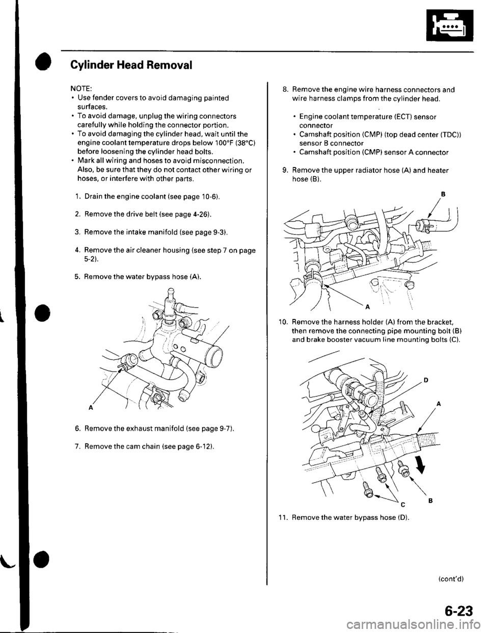
5. Remove the water bypass hose (A).
Remove the exhaust manifold (see page 9-7
Remove the cam chain (see page 6-12).
6.
7.
).
8. Remove the engine wire harness connectors and
wire harness clamps from the cylinder head.
. Engine coolant temperature (ECT) sensor
conneclor. Camshaft position (Cl\4P) (top dead center (TDC))
sensor B connector. Camshaft posilion (CMP) sensor A connector
9. Remove the upper radiator hose (A) and heater
hose (B).
'10. Remove the harness holder (A)from the bracket,
then remove the connecting pipe mounting boh {B)
and brake booster vacuum line mounting bolts {C).
(cont'd)
1 1. Remove the water bvpass hose (D).
6-23