multiplex control HONDA CIVIC 2002 7.G Workshop Manual
[x] Cancel search | Manufacturer: HONDA, Model Year: 2002, Model line: CIVIC, Model: HONDA CIVIC 2002 7.GPages: 1139, PDF Size: 28.19 MB
Page 57 of 1139
Gharging System
Charging Circuit Troubleshooting
lf the charging system indicator does not come on or
does not go off, or the battery is dead or low, test these
items in the order listed below:
Battery (see page 22-50)
Charging system indicator
Alternator and regulator circuit
Alternator control system
Charging System Indicator Test
1. Turn the ignition switch ON {ll).
Does the chatging system indicator come on?
YES Go to step 2.
NO Go to step 3.
2. Start the engine.
Does the charging system indicator go off?
YES-Charging system indicator circuit is OK. Go
to the Alternator and Regulator circuit Test. t
NO-Go to step 3.
3. Turn the ignition switch OFF.
4. Troubleshoot the multiplex control system (see
page 22 172).
ls the multiplex control system OK?
YES Go to step 5.
NO Check the multiplex control system as
indicated by the diagnostic trouble code (DTC) (see
step 8 on page 22-172).1
5. Disconnect the engine wire harness 6P connector
from the starter sub harness 6P connector.
4-22
\"4
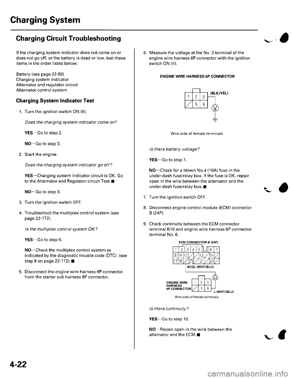
6. Measure the voltage at the No. 3 terminal of the
engine wire harness 6P connector with the ignition
switch ON { ll).
ENGINE WIRE HARNESS 6P CONNECTOR
IBLK/YEL}
Wire side of female terminals
ls there battery voltage?
YES-Go to step 7.
NO-Check for a blown No.4 {10A) fuse in the
under-dash fuse/relay box. lf the fuse is OK, repair
open in the wire between the alternator and the
under-dash fuse/relay box. I
Turn the ignition switch OFF.
Disconnect engine control module (ECM) connector
B (24P).
Check continuity between the ECM connector
terminal B'10 and engine wire harness 6P connector
terminal No. 6.
?
7.
8.
9.
ACGL {WHT/BLU)
ENGINE WIBEHARNESS6PL (WHT/BLUI
Wire side of femaletermina s
ls there continuity?
YES Go to step 10.
NO-Repair open in the wire between the
alternator and the ECN4.I
ECM CONNECTOB A (24P)
Page 638 of 1139
ABS Components
q,
CONNECTOR A {12P)BRAKE PEDAL POSITIONSWITCH 4P CONNECTOR
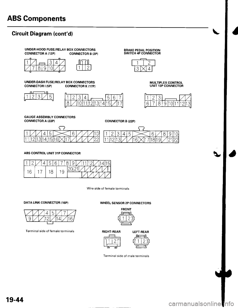
Circuit Diagram (cont'd)
UNDER-HOOD FUSE/RELAY BOX CONNECTORSCONNECTOR A {12P) CONNECTOR B {2P}
UNDER.DASH FUSE/RELAY BOX CONNECTORSCONNECTOR I {5P)CONNECTOR K I17P)MULTIPLEX CONTROLUNIT 13P CONNECTOR
CONNECTOR B I22PI
1l2l3l,/15
GAUGE ASSEMBLY CONNECTORS
CONNECTOR A I22P)
WHEEL SENSOR 2P CONNECTORS
FRONT
J --T:-l Ltqtt/)l'l L_.:-:J r\-r-----Tr'e:l
RIGHT.REAR LEFT-REAR
tslTt?t /J 1T-1\I tL | rlziJ
Terminal side of male lerminals
ABS CONTROL UNIT 3IP CONNECTOR
OATA LINK CONNECTOR {16P)
Terminal side of female terminals
Wire side of female terminals
1234567
810111213141511
123,/ ,/
67891011n213
1245678I11121415
161118192021/1,/1,/vl,/l
/t,/t/t,/t/
19-44
Page 649 of 1139
Brake System Indicator Gircuit Troubleshooting
Brake system indicator does not come on
'1. Discon nect the m ultiplex contro I unit l3Pconnector
and the ABS control unit 31P connector.
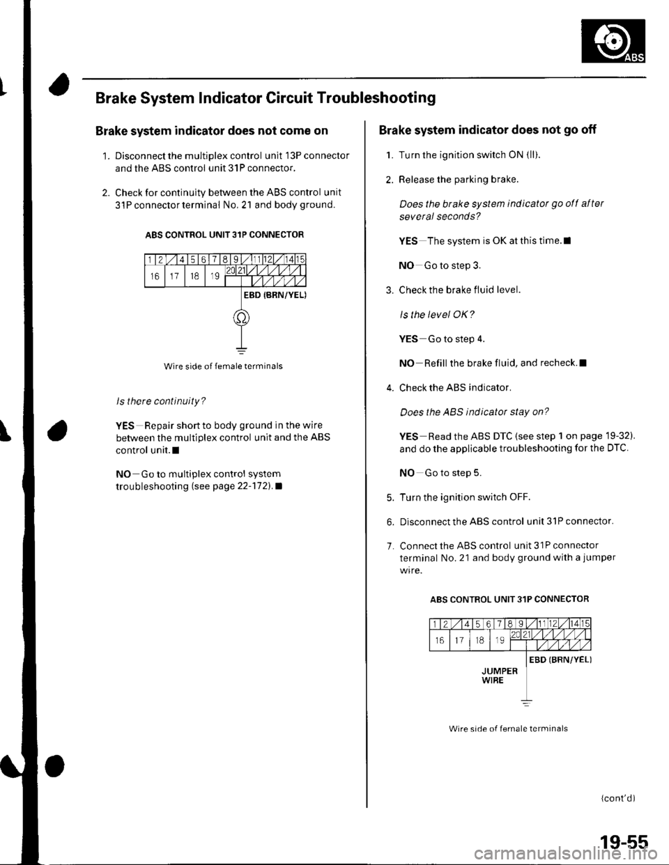
2. Check for continuity between the ABS control unit
3l P connector terminal No,21 and bodyground.
ABS CONTROL UNIT 31P CONNECTOR
Wire side of female terminals
ls there continuity?
YES Repair short to body ground in the wire
between the multiplex control unit and the ABS
control unit.l
NO Go to multiplex control system
trou bleshooting lsee page 22''172).a
Brake system indicator does not go off
1. Turn the ignition switch ON {ll).
2. Release the parking brake.
Does the brake system indicatot go ofl after
several seconds?
YES The system is OK at this time.l
NO Go to step 3.
3. Check the brake fluid level.
ls the level OK?
YES Go to step 4.
NO Refill the brake fluid, and recheck.l
4. Check the ABS indicator.
Does the ABS indicator stay on?
YES Read the ABS DTC (see step 1 on page 19-32).
and do the applicable troubleshooting for the DTC
NO Go to step 5.
5. Turn the ignition switch OFF.
6. Disconnect the ABS control unit3lPconnector.
7. Connect the ABS control unit 31P connector
terminal No. 21 and body ground with a jumper
ABS CONTROL UNIT 31P CONNECTOR
(cont'd )
Wire srde of lemale lerminals
19-55
Page 650 of 1139
ABS Components
8.
9.
10.
11.
12.
13.
Brake System Indicator Gircuit Troubleshooting (cont'd)
Turn the ignititon switch ON (ll).
Check the brake system indicator.
Does the brake system indicatot go off?
YES-Replace the ABS modulator-control unit.l
NO-Go to step 10.
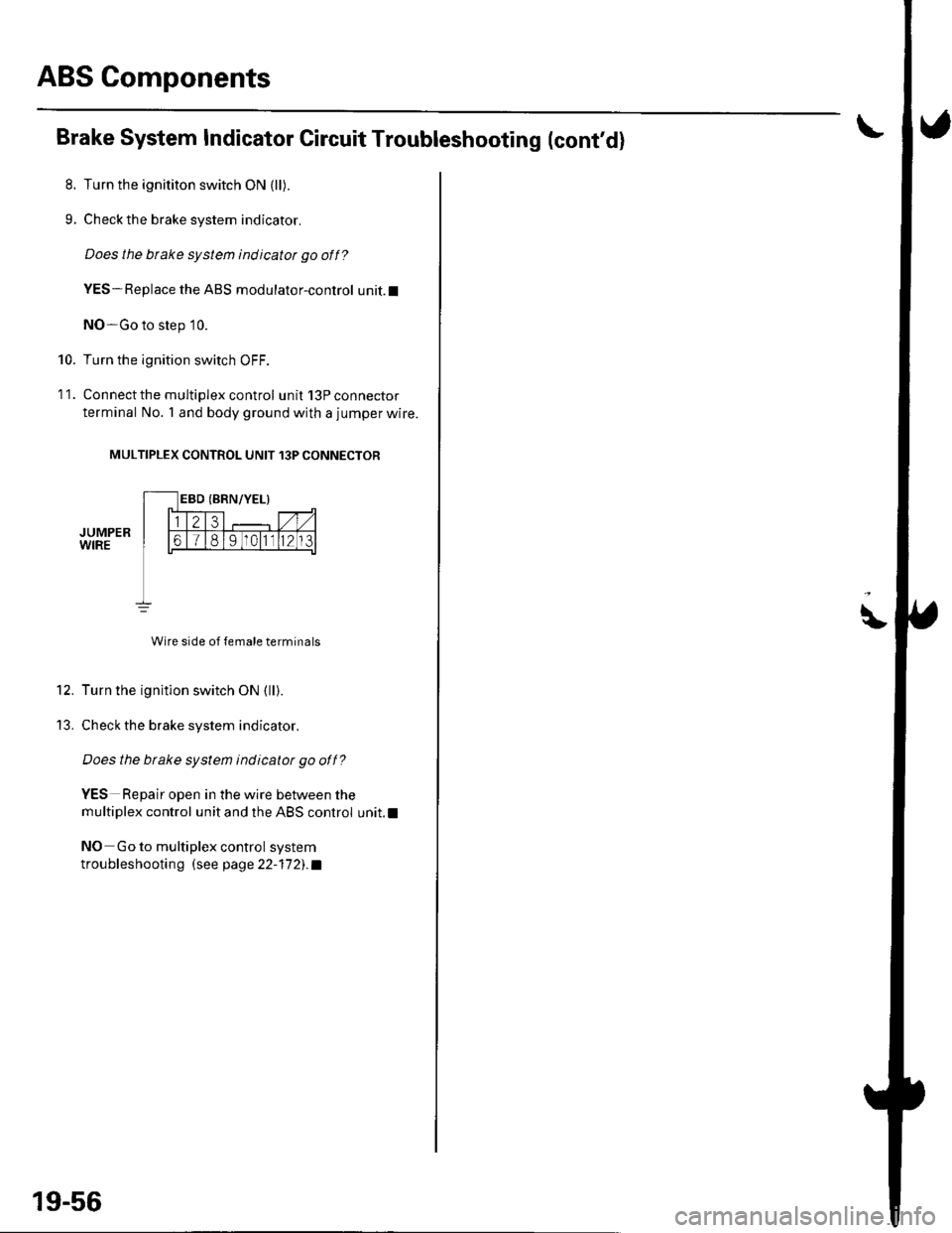
Turn the ignition switch OFF.
Connect the multiplex control unit 13P connector
terminal No. 'l and body ground with a jumper wire.
MULTIPLEX CONTROL UNIT 13P CONNECTOR
JUMPERWIRE
Wire side of female terminals
Turn the ignition switch ON (ll).
Check the brake system indicator.
Does the btake system indicatot go off?
YES Repair open in the wire between the
multiplex control unit and the ABS control unit.l
NO Go to multiplex control system
troubleshootin g (see page 22-17 2). a
19-56
\
Page 804 of 1139
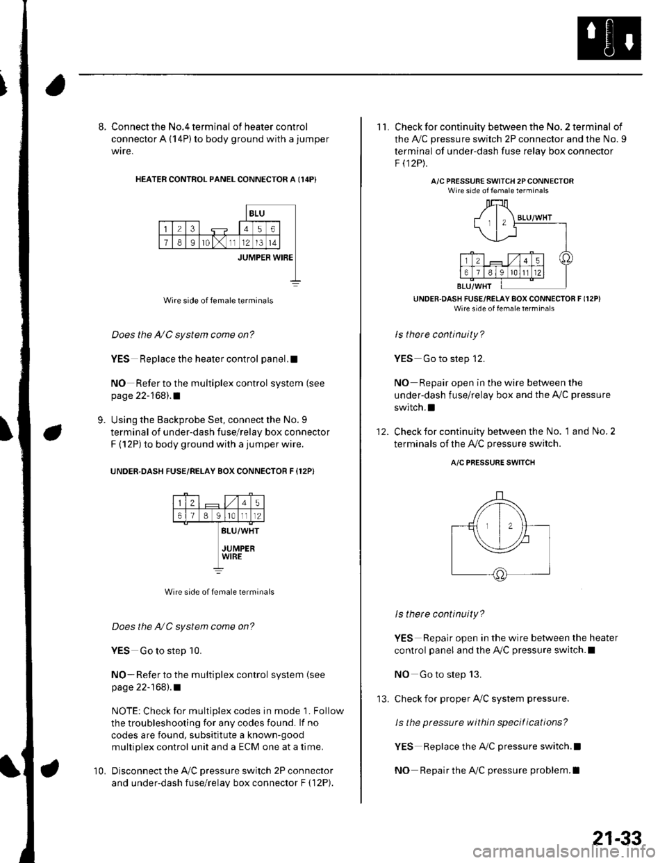
8. Connect the No.4 terminal ofheatercontrol
connector A (14P) to body ground with a jumper
wire,
HEATER CONTROL PANEL CONNECTOR A I14P}
BLU
23456
78Ir0lx1112l3t4
JUMPER WIBE
Wire side of female terminals
Does the A/C system come on?
YES Replace the heater control panel.!
NO Refer to the multiplex control system (see
page 22-168).1
Using the Backprobe Set, connect the No. 9
terminal of under-dash fuse/relay box connector
F (12P) to body ground with a jumper wire.
UNOER.DASH FUSE/RELAY BOX CONNECTOR F {12P}
9.
25
61B g lrotll2
BLU/WHT
JUMPERWIRE
Wire side of female terminals
Does the NC system come on?
YES Go to step 10.
NO- Refer to the multiplex control system (see
page 22-168).1
NOTE: Check for multiplex codes in mode '1. Follow
the troubleshooting {or any codes found. lf no
codes are found, subsititute a known-9ood
multiplex control unit and a ECM one at a time.
Disconnect the Ay'C pressure switch 2P connector
and under-dash fuse/relay box connector F { 12P).
10.
'13.
21-33
11. Check for continuity between the No. 2 terminal of
the A,/C pressure switch 2P connector and the No. 9
terminal of under-dash fuse relav box connector
F t12Pt.
A/C PRESSURE SWITCH 2PCONNECTORWire side of female terminals
UNDER.OASH FUSE/RELAY BOX CONNECTOR F (12P)
Wire side of fenale lerrrinal'
ls there continuity?
YES Go to step 12.
NO Repair open in the wire between the
under-dash fuse/relay box and the A,,/C pressure
switch.I
Check for continuity between the No. 1 and No. 2
terminals of the A,/C pressure switch.
12.
A/C PRESSURE SWITCH
ls there continuity?
YES Repair open in the wire between the heater
control panel and the A,/C pressure switch.l
NO Go to step 13.
check for proper Ay'C system pressure.
ls the pressure within specitications?
YES Replace the AilC pressure switch.l
NO Repair the AilC pressure problem.I
Page 832 of 1139
Power WindowsComponent Location Index ..........
circuit Diagram . .. ............... .........:.::::.::::.:Master Switch Input Test ...........................Master Switch TestDriver's Window Motor Test .....................
Passenger's Window Switch lnput Test ...Passenger's Window Switch Test .............
Passenger's Window Motor Test ..............
lMaster Switch Replacement ......................
Passenger's Window SwitchReplacement
Wipers/WashersComponent Location Index .......................
Circuit DiagramRear Window Wiper Intermiftent
Control Unit Input Test ...........................Wiper/Washer SwitchTesVReplacementControl Unit Input Test ...............................Wiper Motor Test
Washer Motor TestWasher Fluid Level Switch TesV
Replacement (Canadal ..........................
Windshield Wiper Motor Replacement ....
Rear Window Wiper MotorReplacementWasher Reservoir Replacement ................
Washer Tubes Beplacement ......................
Accessory Power SocketCircuit Diagram ......... 22-149
Accessory Power Socket
TesVReplacement ................................... 22-1 49
Keyless/Power Door Lock System
Component Location Index ....................... 22-150
Circuit Diagram ......... 22-151Keyless Receiver Unit InputTest ............... 22-153
Control Unit Input Test ............................... 22-155
Door LockActuatorTest .........,.......,..,.,..... 22-158Hatch LockActuatorTest ........................... 22-159
Door Lock Knob Switch Test ...................... 22-160
Door Lock Switch Test ................................ 22-160
Transmitter Test ....... 22-161
Transmitter Programming ......................... 22-161
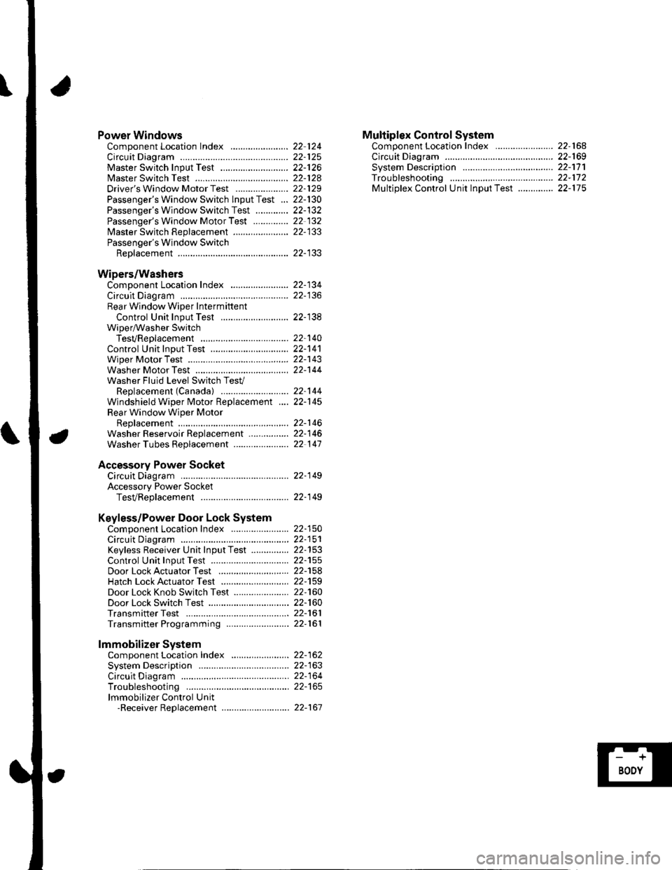
Multiplex Control SystemComponent Location Index ...........
circuit Diagram ...... ........................::.:..:.::.:
Svstem DescriDtionTroubleshootingMultiolex Control Unit InDut Test .............
22 12422-12522-12622-12822-129
22- t30
22-13222 13222-133
22-133
22-134
22-138
22-14022-14122-14322-144
22-14422-145
22-14622-14622 147
22,16422-16922-17'l22,11222-175
lmmobilizer Systemcomponent Location Index ...........
System Description ....... ............. ..:..:..:.:...
Circuit DiagramTroubleshootinglmmobilizer Control Unit-Receiver Replacement ...........................
22-16222-16322-164
22-167
Page 839 of 1139
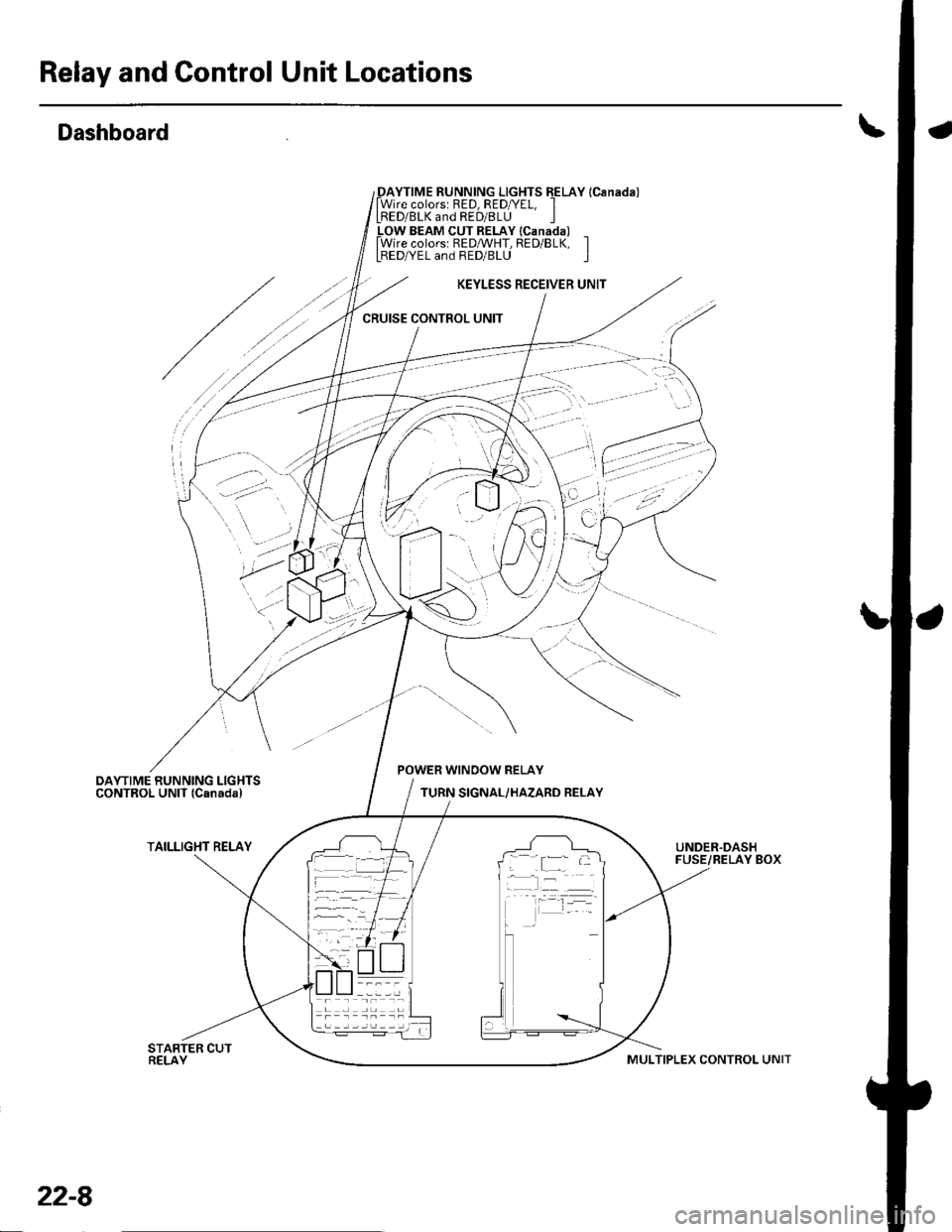
Relay and Gontrol Unit Locations
Dashboard
_DAYTIME RUNNING LIGHTS EELAY lCanada)lWire colorsr RED, RED/YEL, ILRED/BLK and RED/8LU I_LOW BEAM CUT RELAY lcanada) _lWire colors: REDMHT, RED/BLK, ILBEDA/EL and RED/BLU I
KEYLESS RECEIVER UNIT
CRUISE CONTROL UNIT
'
'-.:- ':
..? ;,
POWER WINOOW RELAY
TURN SIGNAL/HAZARD RELAY
TAILLIGHT RELAYUNDER.DASHFUSE/RELAY BOX; .[:_- -
-l:r --
22-8
MULTIPLEX CONTROL UNIT
Page 876 of 1139
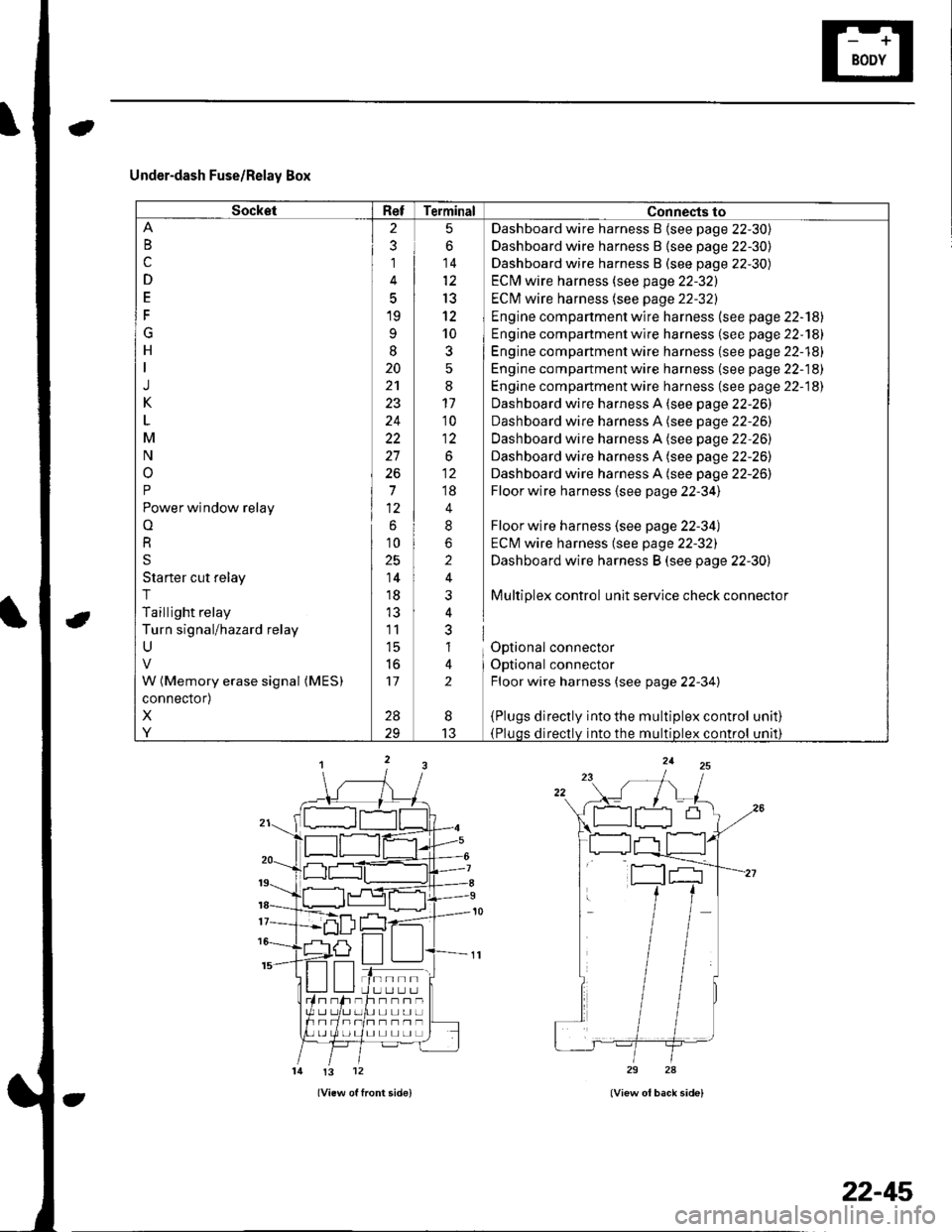
Under-dash Fuse/Relay Box
SocketRefTerminal Connects to
B
c
D
E
F
G
H
J
K
M
N
o
P
Power window relay
o
R
S
Starter cut relay
T
Taillight relay
Turn signal/hazard relay
U
W (Memory erase signal (MES)
connector)
X
Y
2
3
1
5
19
9
I
20
24
22
27
26
7
6
10
25
14
18
11
l5
to
17
28
5
6
14
13
12
10
3
:
11'10
1:
.o^
;;
4
8
2
i
nl
al
lt
2
Dashboard wire harness B {see page 22-30)
Dashboard wire harness B {see page 22-30)
Dashboard wire harness B (see page 22-30)
ECM wire harness (see page 22-32)
ECI\4 wire harness (see page 22-32)
Engine compartment wire harness (see page 22-'l8l
Engine compartment wire harness (se e page 22-181
Engine compartment wire harness (see page 22-18)
Engine compartment wire harness (se e page 22-18)
Engine compartment wire harness (see page 22-18)
Dashboard wire harness A (see page 22-26)
Dashboard wire harness A (see page 22-26)
Dashboard wire harness A (see page 22-26)
Dashboard wire harness A (see page 22-26)
Dashboard wire harness A (see page 22-26)
Floor wire harness (see page 22-34)
Floor wire harness (see page 22-34)
ECM wire harness (see page 22-32)
Dashboard wire harness B (see page 22-30)
Multiplex control unit service check connector
Optional connector
Optional connector
Floor wire harness (see page 22-34)
{Plugs directly into the multiplex control(Pluqs directlv into the multiDlex control
unat)
unrl)
I
13
tn--rlI U LI L.] L.Jh--n-UL]L]UL]
I] L] L] LI L]
!3 12
22-45
Page 877 of 1139
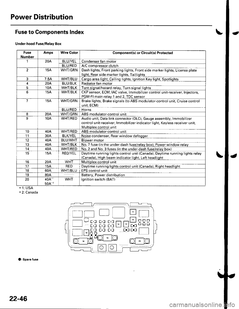
Power Distribution
Fuse to Components lndex
Under-hood Fuse/Relay Box
Fuse
Number
AmpsWire ColorComponent(sl or Circuit(s) Protected
'I204BLUI/ELCondenser fan motor
BLU/REDAy'C compressor clutch
15AWHT/GRNDash lights, Front parking lights, Front side marker lights, License plate
liqht, Rear side marker liqhts, Tailliqhts
7.5AWHT/BLUCarqo area liqht, Ceilinq liqhts. lqnition Kev liqht. Sootliohts
204BLU/BLKRadiator fan motor
510AWHT/BLKTurn siqnal/hazard relav, Turn siqnal liqhts
15AWHT/BLKCKP sensor, ECM, IAC valve, lmmobilizer control unit-receiver, Injectors,
PGM-FI main relav 1 and 2. TDC sensor
715AWHT/GRNBrake lights, Brake signals (to ABS modulator-control unit, Cruise control
unit, ECM)
BLU/REDi1 Orns
820AWHT/GRNABS modulatorcontrol unit
910AWHT/REDAudio unit, Data link connector (DLC), Gauge assembly, lmmobilizer
control unit-receiver, lmmobilizer indicator light. Keyless receiver unil,
lvlultiDlex control unit
1040AWHT/REDABS modulator-control unit
1130AB LK/YE LNoise condenser, Rear window defoqqer
40ABLU^^/HTBlower motor
IJ40AWHT/BLKNo. 7 fuse (in the under-dash fuse/relav box), Power window relav
1440AWHT/REDNo.2 and No.3 fuses (in the under-dash fuse/relav box)
t515AREDI/ELDaytime running lights control unit (Canada), Daytime running lights relay
{Canada), Hioh beam indicator liqht. Left headliqht
16204WHTMultiplex control unit
1715AREDDavtime runninq liqhts control unit (Canada). Rioht headlioht
1860AWHTiBLUEPS control unit
1980ABatterv. Power distribution
2040A'
50A'?
WHTlgnition switch (BAT)
* 1: USA" 2. Canada
O: Spare fuse
t t"| lll Itt 4t I
l l---- E'l E,l E,l r--r r---r t__J i; i6'!/'
E,l E,l E,l Eol E l f__--lI l'lr]n | |I r L__J,a ,..r^{-------l^-,
n[:]$"Lrt " N2, nf - r^l
22-46
Page 878 of 1139
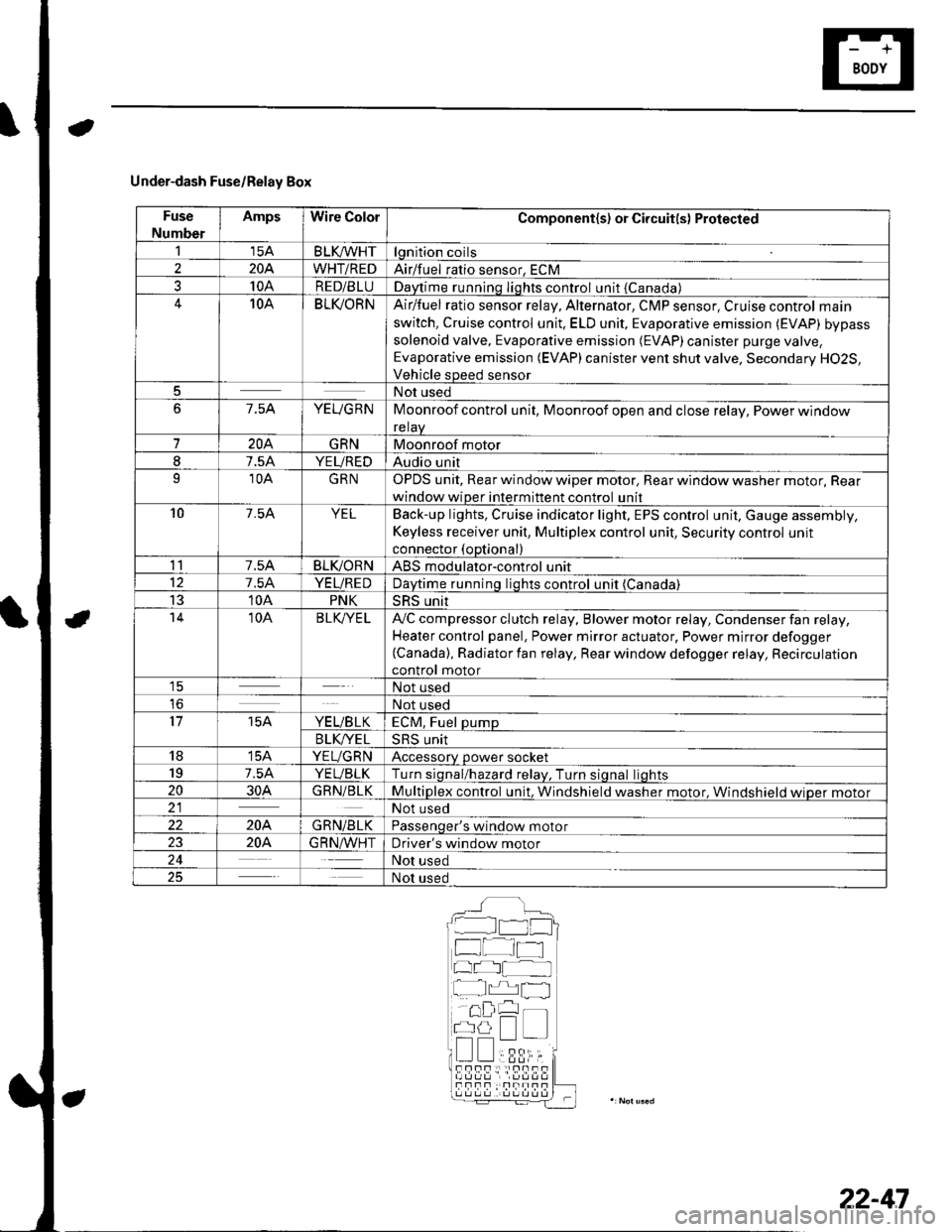
Under-dash Fuse/Relay Box
Fuse
Number
AmpsWire ColorComponent(s) or Circuit(s) Protected
115ABLKA/VHTlgnition coils
2204WHT/REDAirlfuel ratio sensor, ECM
310ARED/BLUDaytime running Iights control unit {Canada)10ABLI(ORNAir/fuel ratio sensor relay, Alternator, CMP sensor, Cruise control main
switch, Cruise control unit. ELD unit, Evaporative emission (EVAP) bypass
solenoid valve, Evaporative emission (EVAP)canister purge valve,
Evaporative emission (EVAP) canister vent shut valve, Secondary H02S,
Vehicle speed sensor
5Not used
67.5AYEUGRNMoonroof control unit, Moonroof open and close relay, Power window
relaV
7204GRNMoonroof motor
I7.5AYEUREDAudio unit
910AGRNOPDS unit, Rear window wiper motor, Rear window washer motor, Rear
window wiper intermittent control unit
107.54YELBack-up lights, Cruise indicator light, EPS control unit, Gauge assembly,
Keyless receiver unit, Multiplex control unit, Security control unit
connector (optional)
117.5ABLIVORNABS modulator-control unit
127.5AYEUREDDaytime runnino liohts control unit (Canada)
1310APNKSRS unit't410ABLK/YE LA,,/C compressor clutch relay, Blower motor relay, Condenser fan relay,
Heater control panel, Power mirror actuator, Power mirror defogger(Canada), Radiator fan relay, Rear window defogger relay, Recirculation
control motor1ENot used
loNot used
1715AYE L/B LKECM, Fuel pump
B LK/YE L>H> Unrr
1815AYEUGRNAccessory power socket
197.5AYEUBLKTurn siqnal/hazard relav, Turn siqnal liohts
2030AGRN/BLKMultiplex control unit, Windshield washer motor. Windshield wioer motor21Not used
22204GRN/BLKPassenqer's window motor
2320A.G R N,A/VHTDriver's window motor
24Not used
25Not used
__^:Hr tl_l
f at-t
at I
r^,rl fl
!!;r -
!339,i;s!!sf Fnf : |rnITf
22-47