washer fluid HONDA CIVIC 2002 7.G Workshop Manual
[x] Cancel search | Manufacturer: HONDA, Model Year: 2002, Model line: CIVIC, Model: HONDA CIVIC 2002 7.GPages: 1139, PDF Size: 28.19 MB
Page 31 of 1139
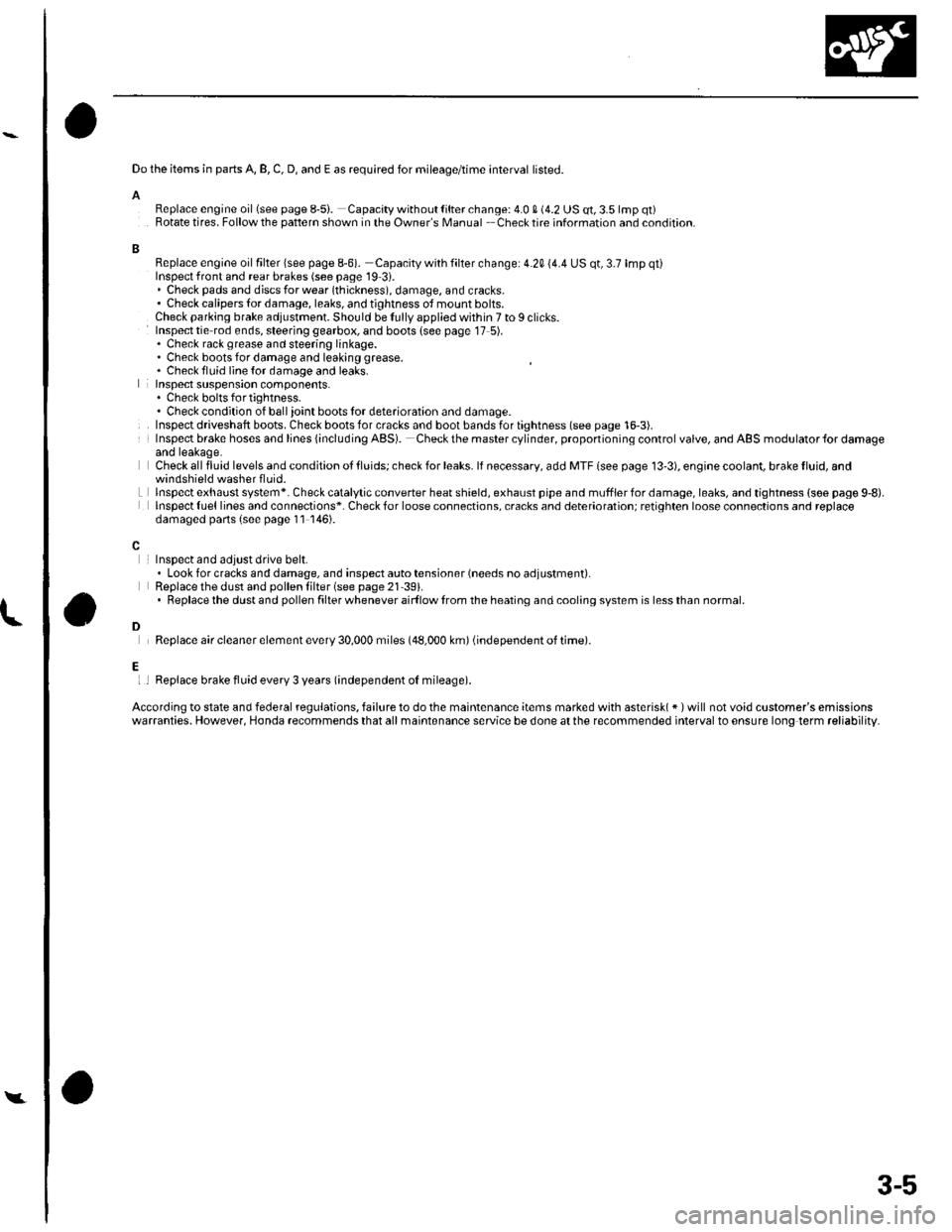
Do the items in parts A, B, C, D, and E as required for mileage/time interval listed.
AReplace engine oillsee page 8-5i. Capacity without lilter change: 4.0 S (4.2 US qt, 3.5 lmp qt)Rotate tires. Follow the pattern shown in the Owner's Manual Checktire information and condition.
BReplace engine oil filter lsee page 8-6). Capacity with filter change: 4.20 (4.4 US qt, 3.7 lmp qt)Inspect front and rear brakes (see page 19 3i.. Check pads and djscs for wear (thickness), damage, and cracks.' Check calipers tor damage, leaks, and tjghtness ot mount bolts.Check parking brake adjustment. Should be Iully applied within 7 to I clicks.Inspect tie rod ends, steering gearbox, and boots {see page 17 5).. Check rack grease and steering linkage.. Check boots for damage and leaking grease. Chack fluid line {or damage and leaks.lnspect suspension components.. Chock bolts fo r tig htness.. Check condition of ball ioint boots lor deterioration and damage.Inspect driveshaft boots. Check boots for cracks and boot bands for tightness (see page 16-3).Insp€ct brake hoses and lines {including ABS). Checkthe mastercylinder, proponioning control valve, and ABS modulator{or damageand leakage.Check all fluid levels and condition ot tluids; check for leaks. lf necessary, add MTF lsee page 13'3), engioe coolant, brake fluid, and
Lwindshield washer fluid.lnspectexhaust system*. Check catalytic converter heatshield, exhaust pipe and mufflerfordamage,leaks, and tightness {soe page 9,8).lnspect {uel lines and connections*. Check for loose connections, cracks and deterioration; retighten loose connoctions and replacedamaged parts (s€e page 11 146).
InsDect and adiust drive belt.. Look for cracks and damage, and inspect auto tensioner (needs no adjustment).Replace the dust and pollen lilter (see page 21 39).. Replacethe dustand pollen filter whenever airf low lrom the heating and cooling system is lessthan normal.
Replace air cleaner element every 30,000 miles (48,000 km) (independent of time).
l
D
Ei I Replace brake fluid every 3 years (independent oI mileage).
According to state and federal regulations, failure to do the maintenance items marked with asterisk( * ) will not void customer's emissionswarranties. However, Honda recommends that all maintsnance service be done at the recommended interval to ensure long term reliability.
Y
3-5
Page 33 of 1139
L
A
I
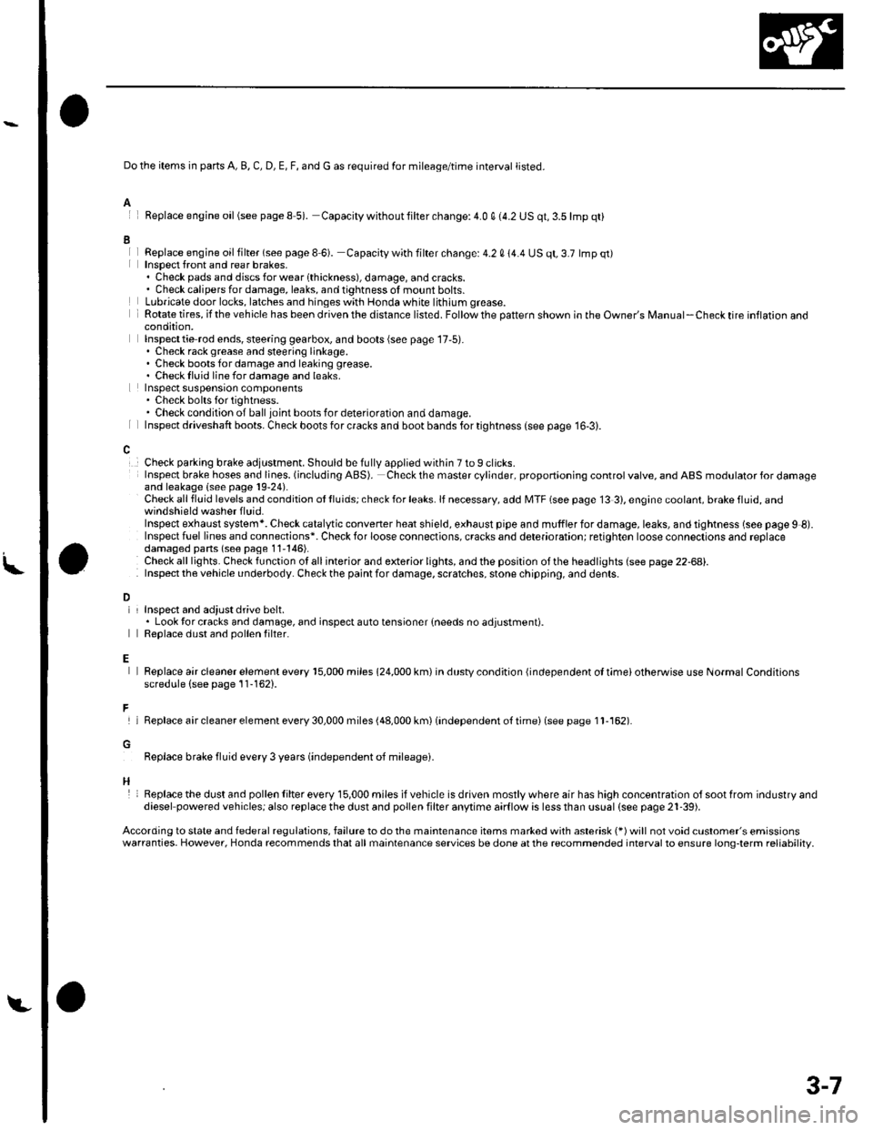
Do the items in parts A, B, C, D, E, F, and G as required for mileage/time interval listed.
Feplace engine oil(see pageS 5). Capacity withoutlilter change:4.0 q (4.2 US qt,3.5lmp qt)
Replace engjne oil filter (see page I 6). Capacity with filter change: 4.2 0 14.4 US qt, 3.7 lmp qt)Insoect front and rear brakes,. Check pads and discsforwearlthickness), damage, andcracks.. Check calipers for damage, leaks, and tightness of mount bolts.Lubricate door locks, latches and hinges with Honda white lithium grease.Rotate tires, if the vehicle has been driven the distance listed. Follow the pattern shown in the Owner's Manual-Check tire inflaron aoocondition,Inspecttie rod ends, steering gearbox, and boots (see page 17,5).. Check rack grease and steering linkage.. Check boots for damage and leaking grease.. Checklluid linefordamage and leaks.Inspect suspensron components. Check bolts for tightness.. Check condition of ball joint boots for deterioration and damage.Inspect driveshaft boots. Check boots for cracks and boot bands for tightness (see page 16-3).
Check parking brake adjustment. Should be fully applied within 7 to 9 clicks.Insp€ct brake hoses and lioes. (including ABS). Check the master cylinder, proportioning control valve, and ABS modulator for damageand leakage (see page 19-24).Check all fluid levels and condition ot lluids; check for leaks. lf necessary, add MTF (see page 13 3), engine coolant, brake fluid, andwindshield washer f luid.Inspect exhaust system*. Check catalytic converter heat shield, exhaust pipe and muffler for damage, leaks, and tightness (see page 9 8).Inspect fuel lines and connections*. Check for loose connections, cracks and deterioration; retighten loose connections and replacedamaged pans (seo page 11'146).Check alllights. Checkfunction otallinterior and exterior lights, andthe position ofthe headlights (see page 22-68).Inspect the v€hicle underbody. Check the paint for damage, scratches, stone chippin0, and dents.
L
D
E
F
H
InsDect and adiust drive belt.. Look tor cracks and damage, and inspect auto tensioner {needs no adjustment).Reolace dust and oollen filter.
Replace air cleaner element every 15,000 miles 124,000 km) in dustv condition {independent ol timei otherwise use Normal Conditionsscredule (see page 11-162).
lReplaceaircleanerelementevery30,000miles(48,000km)(independento{timei(seepagell-162).
Replace brake fluid every 3 years (independent oJ mileagei.
Replacethe dust and pollen Iilter every 15,000 miles ifvehicle is driven mostlywhere air has high concentration olsootfrom industryanddiesel powered vehiclesj also replace the dust and pollen filter anytime aarflow is less than ussal (see pags 21-39).
According to state and federal regulations, failure to do the maintenance items marked with asterisk (*) will not void customer's emissionswarranties. However, Honda recommends that all maintenance services be done at the recommended interval to ensure long-term reliability,
3-7
Page 413 of 1139
Transmission Fluid Inspection and
Replacement
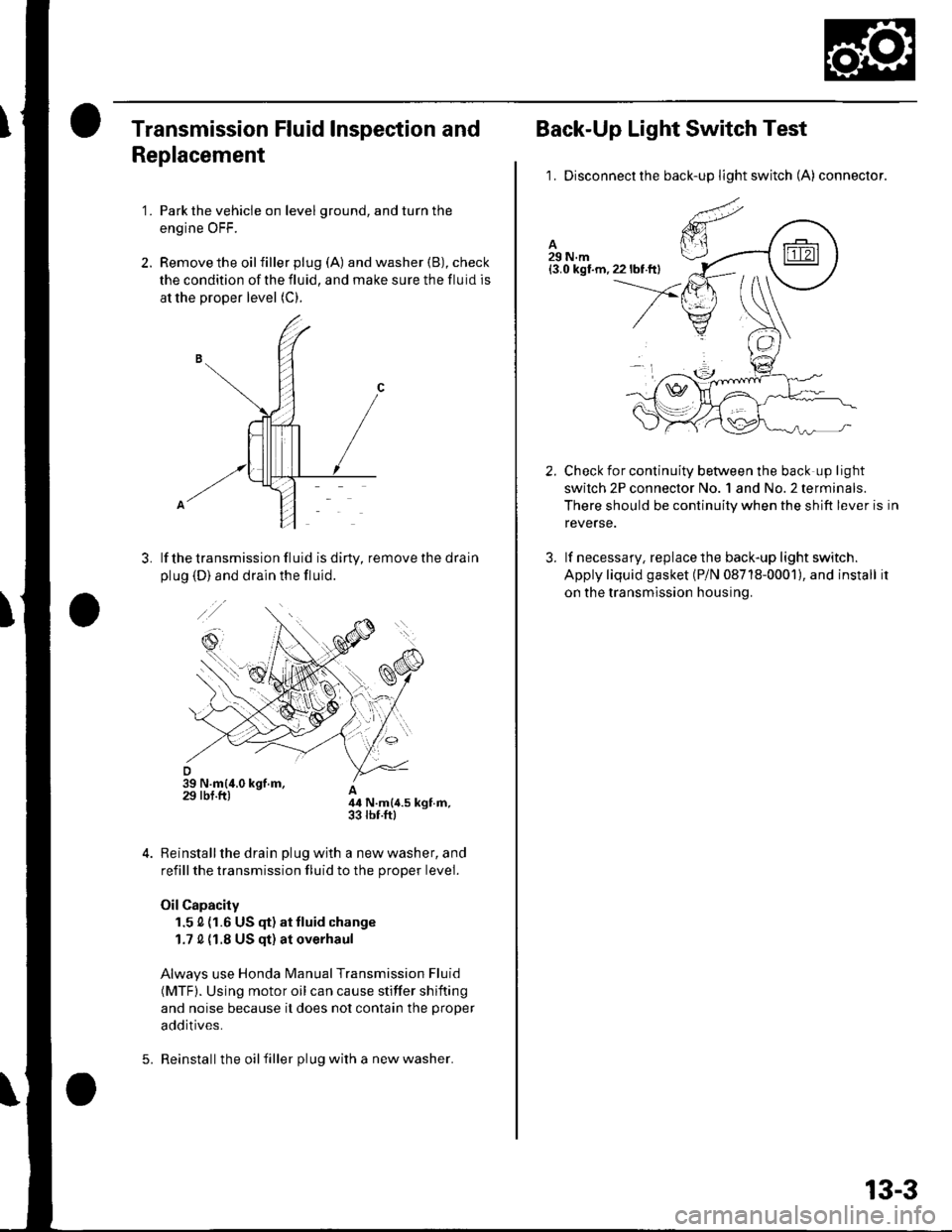
'1. Park the vehicle on level ground, and turn the
engine OFF.
2. Remove the oilfiller plug (A) and washer (B), check
the condition of the fluid, and make sure the fluid is
at the proper level (C).
lf the transmission fluid is diny, remove the drain
plug (D) and drain the fluid.
A44 N.m{4.5 kgt.m,33 rbr.ftl
Reinstall the drain plug with a new washer, and
refill the transmission fluid to the proper level.
Oil Capacity
1.5 0 (1.6 US (F) at tluid change
1.7 0 {1.8 US qt) at overhaul
Always use Honda Manual Transmission Fluid
(MTF). Using motor oil can cause stiffer shifting
and noise because it does not contain the proper
additives.
Reinstall the oil filler plug with a new washer.5.
13-3
Back-Up Light Switch Test
1. Disconnectthe back-up light switch (A) connector.
Check for continuity between the back up light
swilch 2P connector No. 1 and No.2 terminals.
There should be continuity when the shift lever is in
reverse.
lf necessary, replace the back-up light switch.
Apply liquid gasket (P/N 08718-0001), and install it
on the transmission housing.
2.
3.
Page 416 of 1139
Manual Transmission
Transmission Removal (cont'd)
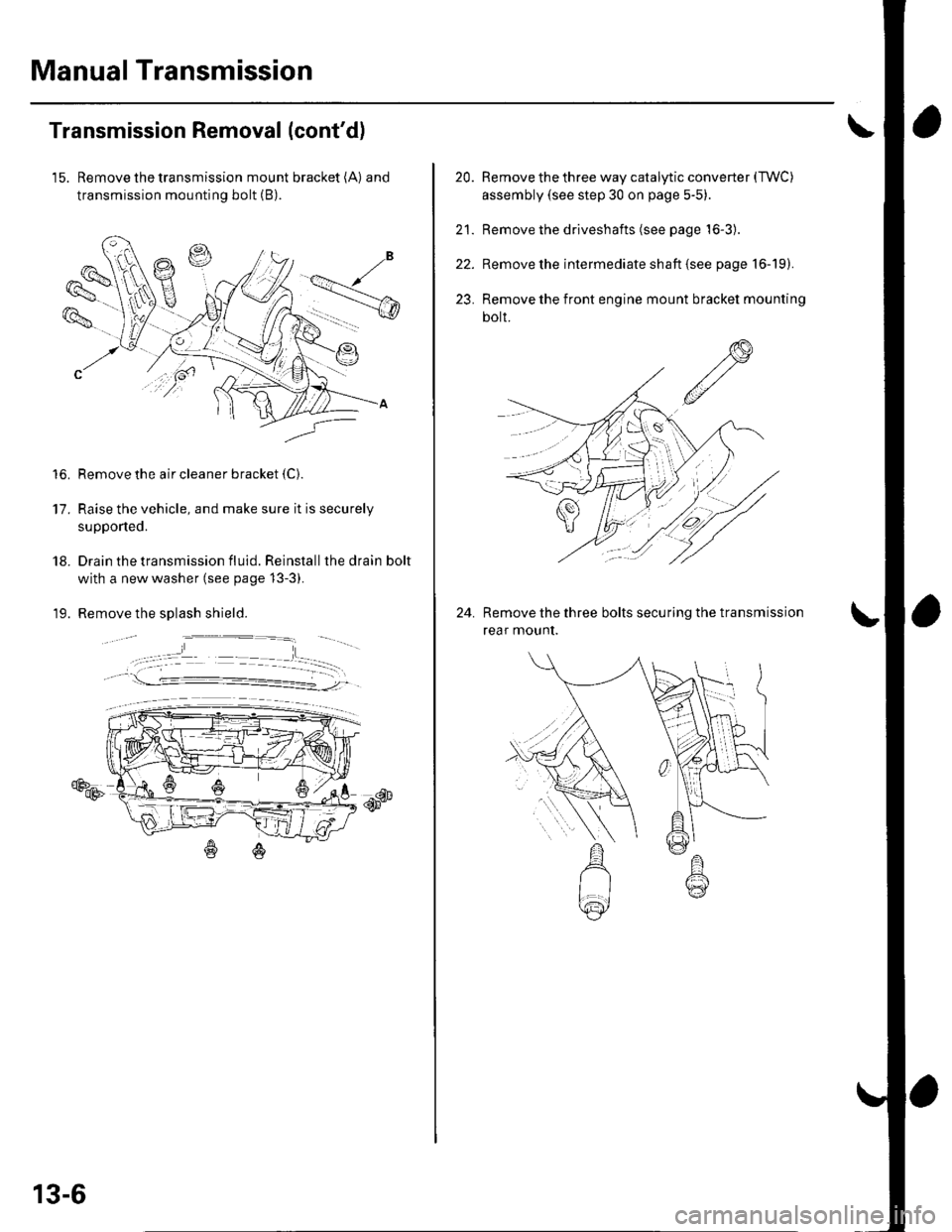
15. Remove the transmission mount bracket (A) and
transmission mounting bolt (B).
Remove the air cleaner bracket {C).
Raise the vehicle, and make sure it is securely
supponed.
Drain the transmission fluid. Reinstall the drain bolt
with a new washer (see page 13-3).
Remove the splash shield.
€Ds
to.
17.
18.
19.
db--qF
13-6
20.
21.
22.
23.
Remove the three way catalytic converter (TWC)
assembly (see step 30 on page 5-5)
Remove the driveshafts (see page 16-3).
Remove the intermediate shaft {see page 16-19).
Remove the front engine mount bracket mounting
bolt.
Remove the three bolts securing the transmission
rear mounI.
24.
Page 470 of 1139
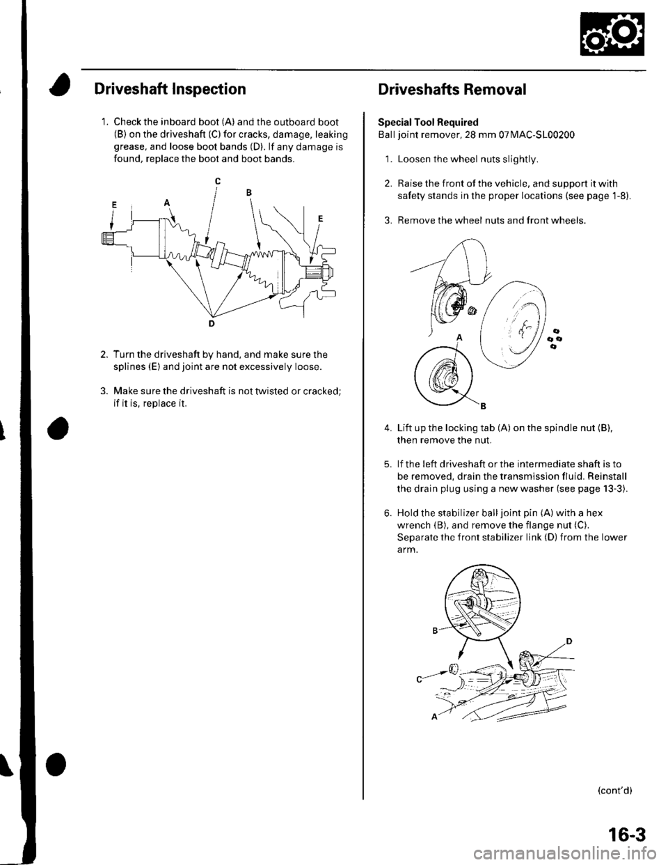
Driveshaft Inspection
1. Check the inboard boot (A) andthe outboard boot(B) on the driveshaft (C) for cracks, damage, leaking
grease, and loose boot bands (D). lf any damage is
found, reDlace the boot and boot bands.
Turn the driveshaft by hand, and make sure the
splines (E) and joint are not excessively loose.
Make sure the driveshaft is not twisted or cracked;
if it is, replace it.
Driveshafts Removal
Special Tool Required
Balljoint remover, 28 mm 07MAC-S100200
1. Loosen the wheel nuts slightly
2. Raise the front of the vehicle, and support it with
safety stands in the proper locations (see page 1-8).
3. Remove the wheel nuts and front wheels.
4.Lift up the locking tab (A) on the spindle nut (B),
then remove the nut.
lf the !eft driveshaft or the intermediate shaft is to
be removed, drain the transmission fluid. Reinstall
the drain plug using a new washer (see page 13-3).
Hold the stabilizer balljoint pin (A) with a hex
wrench {B), and remove the flange nut (C).
Separate the front stabilizer link (D) from the lower
a rm.
(cont'd)
16-3
Page 610 of 1139
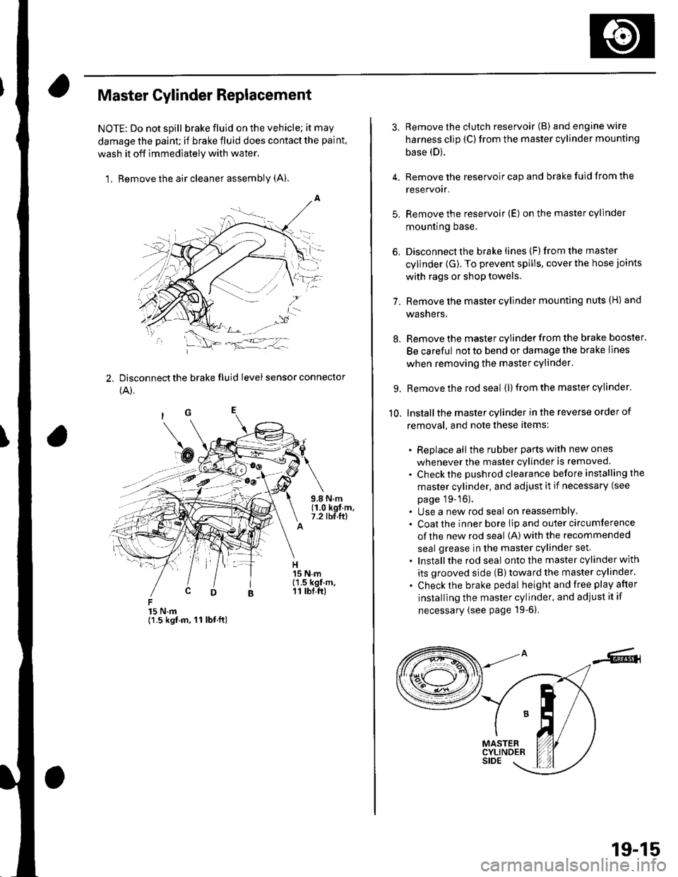
Master Cylinder Replacement
NOTE: Do not spill brake fluid on the vehicle; it may
damage the paint; if brake fluid does contact the paint,
wash it off immediately with water,
1, Remove the air cleaner assembly (A).
2, Disconnect the brake fluid level sensor connector
(A).
15 N.m{1.5 kgt.m, 11 lbt.ft)
3. Remove the clutch reservoir (B) andenginewire
harness clip (C)from the master cylinder mounting
base (D).
4. Remove the reservoir cap and brake fuid from the
reservoir.
5. Remove the reservoir (E) on the master cylinder
mountrng Dase.
6, Disconnect the brake lines (F)from the master
cylinder (G). To prevent spills, cover the hose joints
with rags or shop towels.
7. Remove the master cylinder mounting nuts {H) and
washers.
8. Remove the master cylinder from the brake booster.
Be careful not to bend or damage the brake lines
when removing the master cylinder.
9. Remove the rod seal (l) from the master cylinder.
10. Installthe master cylinder in the reverse order of
removal, and note these items:
. Replace all the rubber parts with new ones
whenever the master cylinder is removed.
. Check the pushrod clearance before installing the
master cylinder. and adjust it if necessary (see
page 19-16).. Use a new rod seal on reassemblY. Coat the inner bore lip and outer circumference
of the new rod seal {A) with the recommended
seal grease in the master cylinder set.
. Installthe rod seal ontothe master cylinder with
its grooved side (B)toward the master cylinder.
. Check the brake pedal height and free play after
installing the master cylinder, and adjust it if
necessary (see page 19-6).
19-15
Page 618 of 1139
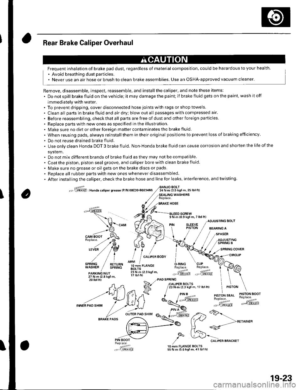
Rear Brake Caliper Overhaul
Frequent inhalation of brake pad dust, regardless of material composition, could be hazardous to your health.
' Avoid breathing dust particles.
. Never use an air hose or brush to clean brake assemblies. Use an OSHA-approved vacuum cleaner'
Remove, disassemble, inspect, reassemble, and installthe caliper, and note these items:
. Donotspill brake fluid on the vehicle; it may damage the paint; if brake f luid gets on the paint, wash it off
immediately with water.. To prevent dripping. cover disconnected hose joints with rags or shop towels.
. Cleanall partsinbrakefluidandairdry;blowoutall passageswith compressed air'
. Before reassembling, check that all parts are free of dust and other foreign particles
. Replace pans with new ones as specified in the illustration.. Make sure no dirt or other foreign matter contaminates the brake fluid.
. When reusing pads, always reinstallthem in their original positions to prevent loss of b ra king efficie ncy.
. Do not reuse drained brake fluid.
. Use only clean Honda DOT 3 brake fluid. Non-Honda brake fluid can cause corrosion and shorten the life of the
system.. Do not mix different brands ot brake fluid as they may not be compatible.
. Coatthe piston, piston seal groove, and caliper bore with clean brake fluid.
. Make sure no grease or oil gets on the brake discs or pads.
. Replaceall rubber parts with new ones whenever disassembled.
. After installing the caliper, check the brake hose and line for leaks, interference. and twisting.
oG , nonau."rip6r qreas€ lP/N 08c30-aoa4Ml34 N.m (3.5 kgf m,25lbtft)BOLT
WASHERS
BRAKE HOSE
a
l,i,,'IltE" / !!;,ff
olT-J,.o"c.O.RING CUPBeplace. Beplace.
.ARKING NUr lii.'i rz.r rgr.. Gd ffi27Nm{2.8kgtm,
\-"o, V((rA ",1 ;[.,.JF /;;;;---
t H\a \l / t,i*t'*"
?,,.t/*"^.,,.:,"", /"V4#
ADJUSTING BOLT
,/
27Nm{2.8kgf.m,20 tbf.ftr PAD SPRING
A,n Na 7lfl,lif,loffi ',,0,n, ,,:,o" \
--t)(*ff l^7k ''"'t!1'ry#'
INNEBPA'SHIM
/ .r.:._U i*E'( ":;*" *dF ,.2>a>-
fr.x{_>@ fftt **-->**^'"
,,.-"iV ,/q &'"o.,"."""o"^.,
: 10 MM FLANGE BOLTS.:r=,9!q!q}l 55 N m (5.6 lgf-m, 4r lbt ft)
19-23
Page 620 of 1139
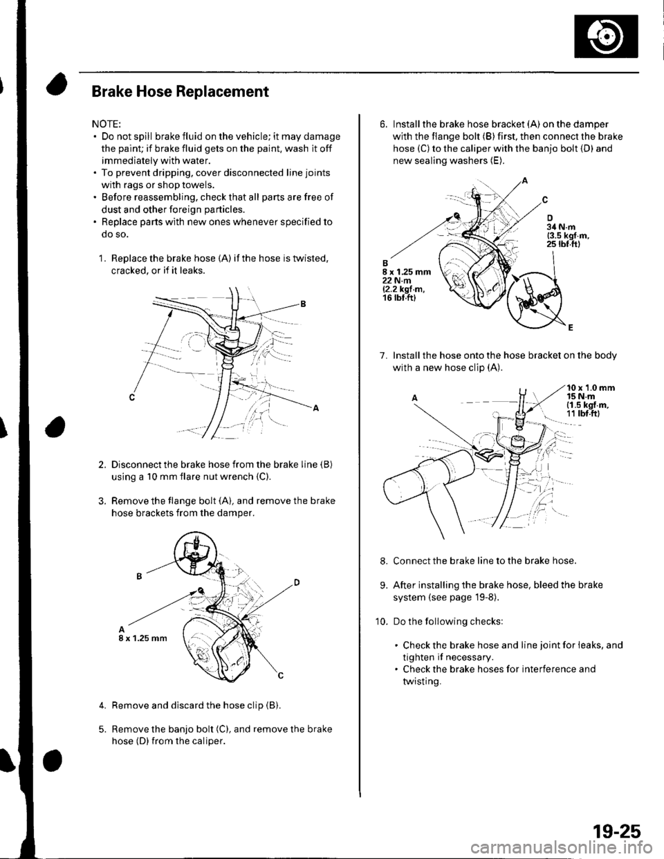
Brake Hose Replacement
NOTE:. Do not spill brake fluid on the vehicle; it may damage
the paint; if brake fluid gets on the paint, wash it off
immediately with water.. To prevent dripping, cover disconnected line joints
with rags or shop towels.. Before reassembling, check that all parts are free of
dust and other foreign particles.
. Replace parts with new ones whenever specified to
do so.
1 . Replace the brake hose (A) if the hose is twisted,
cracked, or if it leaks.
Disconnect the brake hose from the brake line (B)
using a 10 mm flare nut wrench {C)
Remove the flange bolt (A), and remove the brake
hose brackets from the damper.
Remove and discard the hose clip (B).
Remove the banjo bolt (C), and remove the brake
hose (D) {rom the caliper.
4.
I x 1.25 mm
6. Installthe brake hose bracket (A)on the damper
with the flange bolt (B) first, then connect the brake
hose (C) to the caliper with the banjo bolt {D) and
new sealing washers (E).
7. lnstallthe hose onto the hose bracket on the bodv
with a new hose clip (A).
10 x 1.0 mm15 N.mi (1.5 kgf.m,
! 1t tbt.ftl
Connect the brake line to the brake hose.
After installing the brake hose, bleed the brake
system (see page l9-8).
Do the following checks:
. Check the brake hose and line joint for leaks, and
tighten if necessary.. Check the brake hoses for interference and
twisting.
9.
10.
19-25
Page 832 of 1139
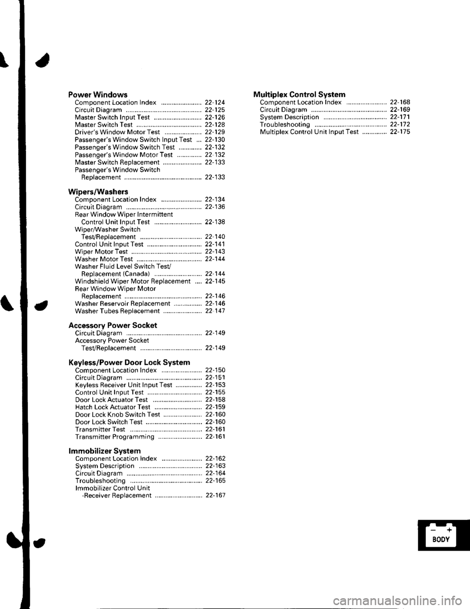
Power WindowsComponent Location Index ..........
circuit Diagram . .. ............... .........:.::::.::::.:Master Switch Input Test ...........................Master Switch TestDriver's Window Motor Test .....................
Passenger's Window Switch lnput Test ...Passenger's Window Switch Test .............
Passenger's Window Motor Test ..............
lMaster Switch Replacement ......................
Passenger's Window SwitchReplacement
Wipers/WashersComponent Location Index .......................
Circuit DiagramRear Window Wiper Intermiftent
Control Unit Input Test ...........................Wiper/Washer SwitchTesVReplacementControl Unit Input Test ...............................Wiper Motor Test
Washer Motor TestWasher Fluid Level Switch TesV
Replacement (Canadal ..........................
Windshield Wiper Motor Replacement ....
Rear Window Wiper MotorReplacementWasher Reservoir Replacement ................
Washer Tubes Beplacement ......................
Accessory Power SocketCircuit Diagram ......... 22-149
Accessory Power Socket
TesVReplacement ................................... 22-1 49
Keyless/Power Door Lock System
Component Location Index ....................... 22-150
Circuit Diagram ......... 22-151Keyless Receiver Unit InputTest ............... 22-153
Control Unit Input Test ............................... 22-155
Door LockActuatorTest .........,.......,..,.,..... 22-158Hatch LockActuatorTest ........................... 22-159
Door Lock Knob Switch Test ...................... 22-160
Door Lock Switch Test ................................ 22-160
Transmitter Test ....... 22-161
Transmitter Programming ......................... 22-161
Multiplex Control SystemComponent Location Index ...........
circuit Diagram ...... ........................::.:..:.::.:
Svstem DescriDtionTroubleshootingMultiolex Control Unit InDut Test .............
22 12422-12522-12622-12822-129
22- t30
22-13222 13222-133
22-133
22-134
22-138
22-14022-14122-14322-144
22-14422-145
22-14622-14622 147
22,16422-16922-17'l22,11222-175
lmmobilizer Systemcomponent Location Index ...........
System Description ....... ............. ..:..:..:.:...
Circuit DiagramTroubleshootinglmmobilizer Control Unit-Receiver Replacement ...........................
22-16222-16322-164
22-167
Page 849 of 1139
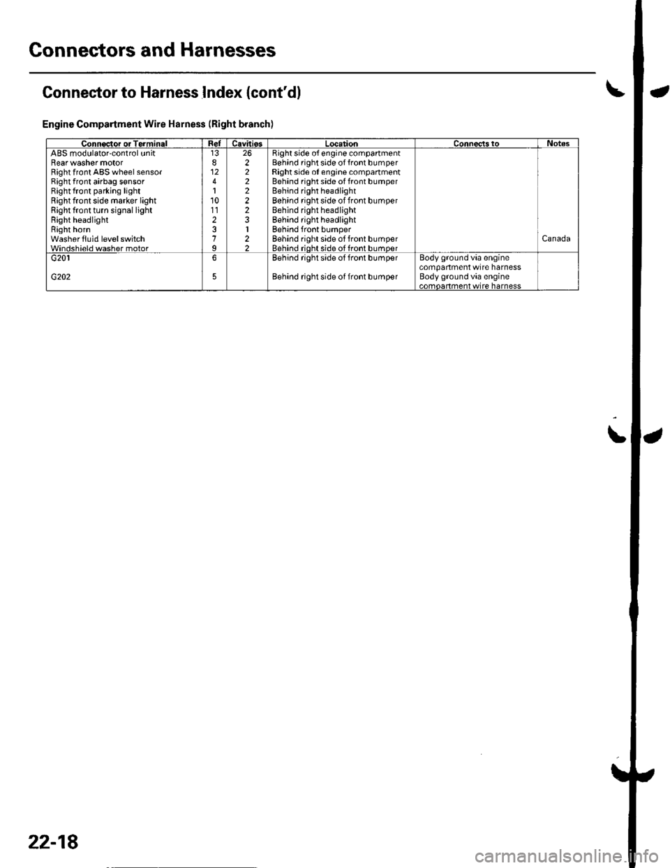
Connectors and Harnesses
Connector to Harness Index {cont'dl
Engine Compartment Wire Harness (Right branch)
\
Connsctor or TerminalCavitissLocationConnects toNotesABS modulator-control unitBearwasher motorRight front ABS wheel sensorRight front airbag s€nsorBightfront parking lightRight front side marker lightRight front turn signal lightRight headlightRight hornwash€rfluid level switchWindshield washer motor
812
110112
7
222222
I22
Bight side o{ engine compartmentBehind right side of {ront bumperRight side ot engine compartmentBehind right side of front bumperBehind right headlightBehind rightside of Jront bumperBehind right headlightBehind right headlightBehind front bumperBehind rightside of tront bumperBehind rioht side of front bumoerCanada
G202
G2016Behind rightside of tront bumper
Behind rightside of Jront bumper
Body ground via €nginecompartment wtre harnessBody ground via engine.omnerhent wire harness
22-18