radiator replacement HONDA CIVIC 2003 7.G Workshop Manual
[x] Cancel search | Manufacturer: HONDA, Model Year: 2003, Model line: CIVIC, Model: HONDA CIVIC 2003 7.GPages: 1139, PDF Size: 28.19 MB
Page 191 of 1139
Engine Cooling
Cooling System
Component Location Index ......................................... 10-2
Radiator Cap Test ..................... .......... 10-3
RadiatorTest ............. 10-3
Fan Motor Test .......... l0-4
Thermostat Test ...................... ........... 10-4
Water Pump Inspection ..................... 10-5
Water Pump Replacement ................. 10-5
Coolant Check .............. ....................... 10-6
Coolant Replacement ......................... 10-6
Thermostat Replacement .................. 10-8
Water Passage Installation ................ 10-9
Water Outlet Installation .................... 10-9
Radiator and Fan Replacement ................................... 10-10
Fan Controls
Component Location Index ......................................... 10-11
Symptom Troubleshooting Index ............................... 10-12
Circuit Diagram ......... 10-13
Radiator Fan CircuitTroubleshooting ........................ 10-14
Radiator Fan Switch Circuit Troubleshooting
(Open) ............ ........ 10-16
Radiator Fan Switch Circuit Troubleshooting
(Short) ............ ........ 10-16
Radiator Fan Switch Test ................... 10-17
Radiator Fan Switch Reolacement .............................. 10-17
Page 192 of 1139
Cooling System
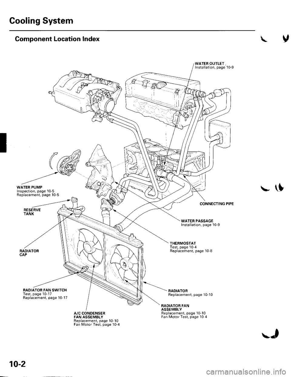
Component Location Index
WATER PUMPInspection, page 10-5Replacement. page 10-5
RESERVETANK
RADIATORCAP
RAOIATOR FAN SWITCHTest, page 10-17Replacement, page 10'17
\
WATER OUTLET,Installation, page'10-g
\f
CONNECTING PIPE
WATER PASSAGEInstallation, page 10-9
THERMOSTATTest, page 10 4Replacement, page 10 8
RADIATORReplacement, page 10-'l0
RADIATOR FANASSEMgLYReplacement, page 10-10Fan MotorTest, page 10 4A/C CONDENSERFAN ASSEMBLYReplacement, page 10 10Fan Motor Test, page '10-4
10-2
\J
Page 195 of 1139
1.
2.
Water Pump Inspection
Remove the drive belt (see page 4-26),
Turn the water pump pulley counterclockwise.
Check that it turns freely.
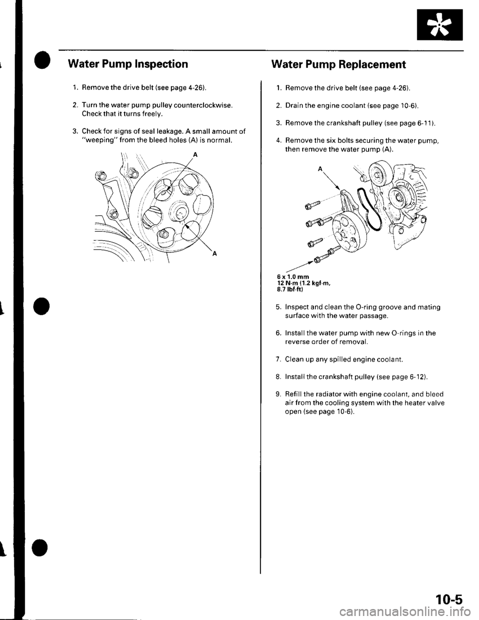
Check for signs of seal leakage. A small amount of"weeping" from the bleed holes (A) is normal.
Water Pump Replacement
1. Remove the drive belt (see page 4-26).
2. Drain the engine coolant {see page 10-6).
3. Remove the crankshaft pulley (see page 6-11).
4. Remove the six bolts securing the water pump,
then remove the water pump (A).
6x1.0mm12 N m {1.2 kgt m,8.7 rbf.ft)
Inspect and clean the O-ring groove and mating
surface with the water passage.
Installthe water pump with new O rings in the
reverse order of removal.
7. Clean up any spilled engine coolant.
8. Installthe crankshaft pulley (see page 6-12).
L Refill the radiator with engine coolant, and bleed
air from the cooling system with the heater valve
open {see page 10-6}.
10-5
Page 196 of 1139
Cooling System
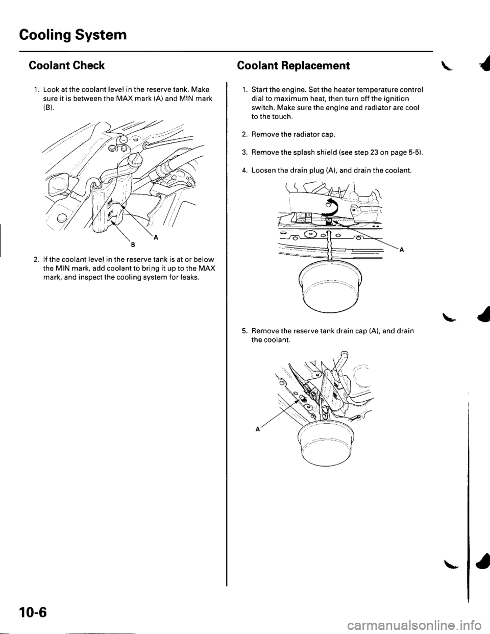
1 . Look at the coolant level in the reserve tank. Make
sure it is between the MAX mark (A) and MIN mark(B),
Goolant Check
lf the coolant level in the reserve tank is at or below
the MIN mark, add coolant to bring it up to the l\4AX
mark, and inspect the cooling system for leaks.
10-6
\-
Coolant Replacement
1.
\
Start the engine. Set the heater temperature control
dial to maximum heat. then turn off the ignition
switch. Make sure the engine and radiator are cool
to the touch.
Remove the radiator cap.
Remove the splash shield (see step 23 on page 5-5).
Loosen the drain plug (A), and drain the coolant.
Remove the reserve tank drain cap (A), and drain
the coolant.
\
Page 198 of 1139
Gooling System
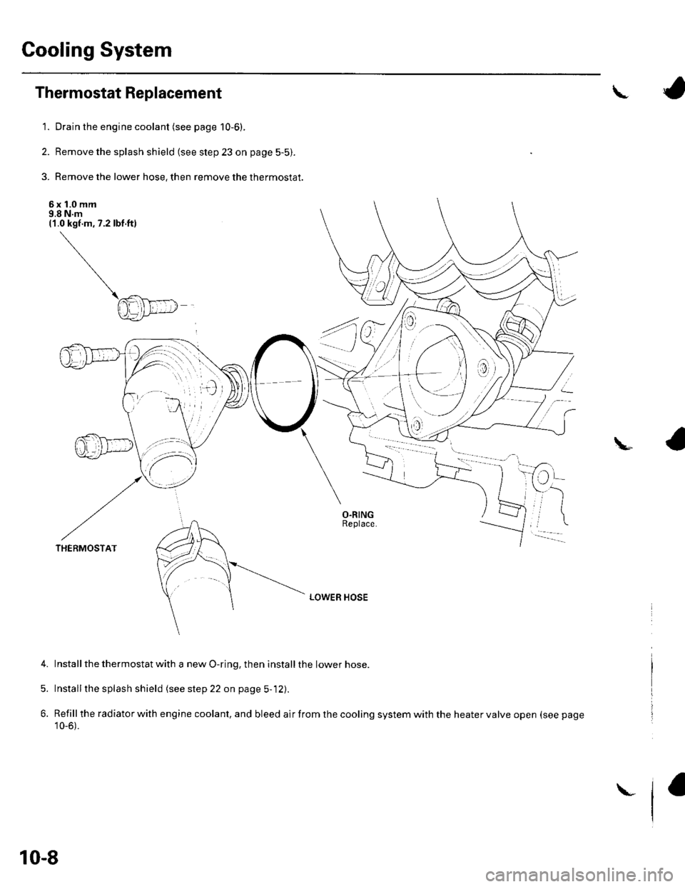
Thermostat Replacement
1. Drain the engine coolant (see page 10-6).
2. Remove the splash shield (see step 23 on page 5-5).
3. Remove the lower hose, then remove the thermostat.
6x 1.0 mm9.8 N.m(1.0 kgf.m,7.2lbf ft)
a
u
i*
-
LOWER HOSE
4. Installthe thermostat with a new O-ring, then installthe lower hose.
5. Installthe splash shield (see step 22 on page 5-12).
6. Refillthe radiator with engine coolant, and bleed air from the cooling system with the heater valve open (see page
10_6).
THERMOSTAT
10-8
\_
Page 200 of 1139
Cooling System
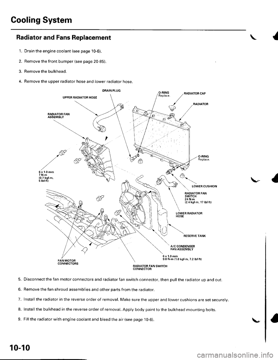
Radiator and Fans Replacement
1. Drain the engine coolant (see page 10-6).
2. Remove the front bumper {see page 20,85).
3. Remove the bulkhead.
4. Remove the upper radiator hose and lower radiator hose.
DRAIN PLUG
UPPER BADIATOR HOSE
BAOIATOA FANASSEMBLY
{
O.RINGRADIATOR CAP
BADIATOB
LOWERCUSHION
\-
RADIATOR FANswtTcH24Nm{2.1t kgl m. 17lbl hl
LOWER FADIATORHOSE
RESERVETANK
A/C CONDENSERFAN ASSEMBLY
9.8 N m {1.0 kgf m,7.2 lbf ft)CONNECTORSRADIATOB FAN SWITCHCONNECTOB
5. Disconnect the fan motor connectors and radiator fan switch connector, then pull the radiator up and out.
6. Remove the fan shroud assemblies and other parts from the radiator.
7. Installthe radiator in the reverse order of removal. Make sure the upper and lower cushions are set securelV.
8. Install the bulkhead in the reverse order of removal. Apply body paint to the bulkhead mounting bolts.
9. Fill the radiator with engine coolant and bleed the air (see page 10-6).
10-10
\.
Page 201 of 1139
Fan Controls
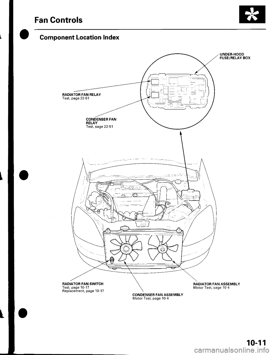
Component Location Index
RADIATOR FAN RELAY
RADIATOB FAN SWITCHTest, page 10'17Replacement, page'10-17
UNDER.HOODFUSE/RELAY BOX
RADIATOR FAN ASSEMBLYMotor Test, page 10 4
CONDENSER FAN ASSEMBLYMotor Test, page 10-4
10-11
Page 207 of 1139
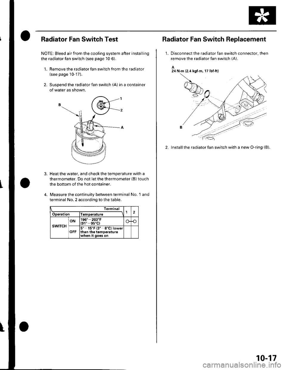
Radiator Fan Switch Test
NOTE: Bleed air from the cooling system after installing
the radiator fan switch (see page 10-6).
1, Remove the radiator fan switch from the radiator
(see page 10-17).
2. Suspend the radiator fan switch (A) inacontainer
of water as shown.
3. Heat the water, and check the temperature with a
thermometer. Do not let the thermometer (B) touch
the bottom of the hot conlainer.
4. Measure the continuity between terminal No. 1 and
terminal No. 2 according to the table.
Termina
Operation lTemperature1
swtTcH
ON196" 203'F(91" gs"C)
OFF5' 15'F {3' 8'C) lowelthan the temoeraturewhen it goes on
Radiator Fan Switch Replacement
1.Disconnect the radiator fan switch connector, then
remove the radiator fan switch (A).
A24 N m (2.4 kgt.m, 17 lbt.ftl
2. Installthe radiator fan switch with a new O-ring (B).
10-17
Page 773 of 1139
21-2
z t-'5
z t-o
z t-o
21-8
21-9
21-10
21-11
21-14
z t- to
HVAC (Heating, Ventilation, and Air Gonditioningl
Heating and Air Conditioning
SpecialTools
Comoonent Location lndex ........
A/C Service Tios and
Precautions
A,/C Refrigerant Oil
ReDlacement
General Troubleshooting
lnformation
DTC Troubleshooting Index .......
Symptom Troubleshooting
1ndex..............
System Description .....................
Circuit Diagram
DTC Troubleshooting ..................
Recirculation Control Motor
CircuitTroubleshooting .......... 21-25
Heater Control Power and Ground
Circuits Troubleshooting ........ 21-27
Condenser Fan Circuit
Troubleshooting ...................... 21-28
Radiator and Condenser Fans
Common Circuit
Troubfeshooting ...................... 21-29
Compressor Clutch Circuit
Troubleshooting ...................... 21-30
A,/C Pressure Switch Circuit
Troubleshooting ...................... 21-32
Air Mix Control Motor
Test and Reolacement ............. 21-34
Mode Control Motor
Test and Replacement ............. 21-35
Recirculation Control Motor
Test and Reolacement ............. 21-36
Evaporator Temperature Sensor
Reolacement and Test ............. 21-31
Power Transistor Test ................. 21 -38
Heater Control Panel and
Push Switch Assemblv
Removal and Installation ........ 21-38
Dust and Pollen Filter
Reolacement ..21-39
Blower Unit Removal and
lnstallation ...... 21-39
Blower Unit Comoonents
ReDlacement ............................ 21-41
Evaporator Core
Reolacement ..21-42*Heater Unit/Core
ReDlacement ..21-43
Heater Valve Cable
Adjustment .....21-46
CompressorReplacement .......... 21-47
Comoressor Clutch Check .......... 21-48
Comoressor Clutch Overhaul ..... 21-49
Compressor Thermal Protector
Reo1acement ............................ 21-51
Comoressor Relief Valve
Reolacement ............................ 21-51
Condenser Reolacement ............ 21-52
Refrigerant Recovery .................. 21-53
System Evacuation ...................... 21-54
System CharginS ......................... 21-55
Refrigerant LeakTest .................. 21-56
A,/C Svstem Tests ........................ 21-57
Page 814 of 1139
Heater Unit/Core Replacement
SRS components are located in this area. Review the
SRS component locations (see page 23'13), and
precautions and procedures (see page 23-14) in the SRS
section before performing repairs or service.
1. Make sure you have the anti-theft code forthe radio,
then write down the freouencies for the radio's
Dreset buttons.
4.
Disconnect the negative cable from the battery,
Disconnect the suction and receiver lines from the
evaporator core (see page 21-42).
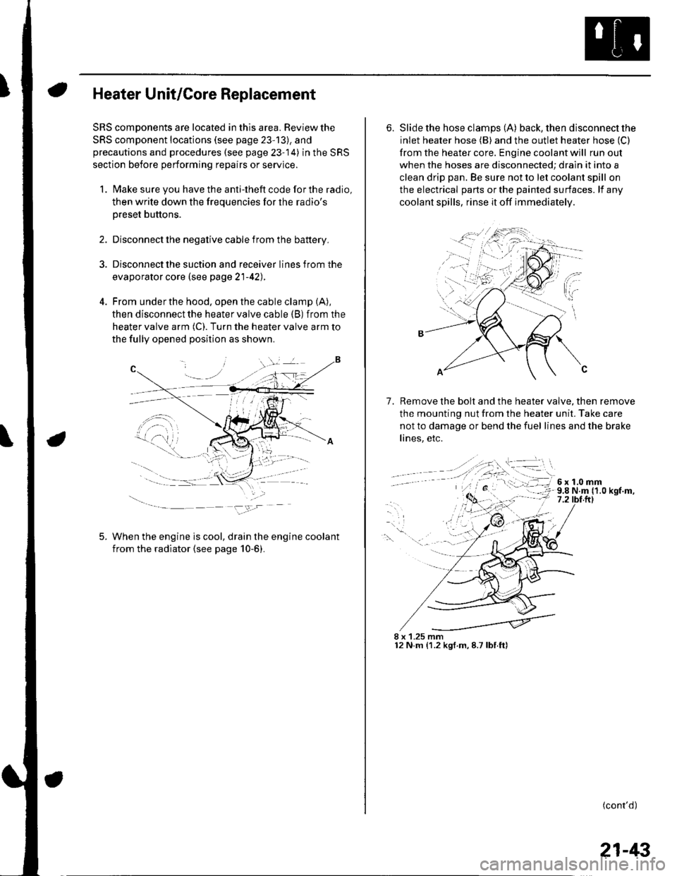
From under the hood, open the cable clamp (A),
then disconnect the heater valve cable (B) from the
heater valve arm (C). Turn the heater valve arm to
the fully opened position as shown
When the engine is cool, drain the engine coolant
from the radiator (see page 10-6).
6. Slide the hose clamps (A) back, the n d isconnect the
inlet heater hose (B) and the outlet heater hose (C)
from the heater core. Engine coolant will run out
when the hoses are disconnected; drain it into a
clean drip pan. Be sure not to let coolant spill on
the electrical parts or the painted surfaces. lf any
coolant spills, rinse it off immediately.
Remove the bolt and the heater valve, then remove
the mounting nut from the heater unit. Take care
not to damage or bend the fuel lines and the brake
lines, etc.
7.
8 x 1.25 mm12 N.m (1.2 kgf.m,8.7lbf.ft)
(cont'd)
21-43