ect HONDA CIVIC 2003 7.G Workshop Manual
[x] Cancel search | Manufacturer: HONDA, Model Year: 2003, Model line: CIVIC, Model: HONDA CIVIC 2003 7.GPages: 1139, PDF Size: 28.19 MB
Page 163 of 1139
5. Installthe bearing halves in the cylinder block and
conneclrng rods.
6. Apply a coat of engine oilto the main bearings and
rod bearings.
7. Hold the crankshaft so rod journal No.2and rodjournal No. 3 are straight up, and lower the
crankshaft into the block.
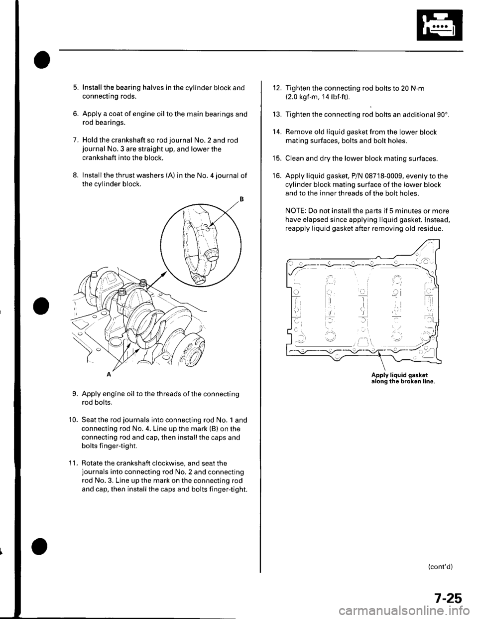
8. lnstallthe thrust washers (A) in the No. 4 journal of
the cylinder block.
Apply engine oil to the threads ot the connecting
rod bolts,
Seat the rod journals into connecting rod No. 1 and
connecting rod No. 4. Line up the mark (B) on the
connecting rod and cap, then installthe caps and
bolts finger-tight.
Rotate the crankshaft clockwise, and seat thejournals into connecting rod No.2 and connecting
rod No. 3. Line up the mark on the connecting rod
and cap, then install the caps and bolts finger-tight.
9.
10.
'11 .
\-1
12. Tighten the connecting rod bolts to 20 N.m(2.0 kgf.m, 14 lbf.ft).
13. Tighten the connecting rod bolts an additional 90".
14. Remove old liquid gasket from the lower block
mating surfaces, bolts and bolt holes.
15. Clean and dry the lower block mating surfaces.
16. Apply liquid gasket, P/N 08718-0009, evenly to the
cylinder block mating surface of the lower block
and to the innerthreads ofthe bolt holes.
NOTE: Do not install the parts if 5 minutes or more
have elapsed since applying liquid gasket. Instead,
reapply liquid gasket after removing old residue.
(cont'd)
.\
,i,
Apply liquid gasketalong the broken line.
7-25
Page 166 of 1139
Engine Block
Oil Pan Installation (cont'dl
6. lf the engine is still in the vehicle, install the
subframe,
-1 Installthe subframe. Align the reference lines
on the subframe with the bolt head center, then
tighten the bolts (see step 5 on page 5-10).-2 Tighten the front mounting bolt (see step 6 onpage 5-10).-3 Tighten the rear mount mounting bolts (see
step 7 on page 5-11).-4 Connect the suspension lower arm ball joints
(see step 6 on page 18-19).
7. After assembly, wait at least 30 minutes before
filling the engine with oil.
7-28
v
Transmission End Grankshaft Seal
Installation - In Car
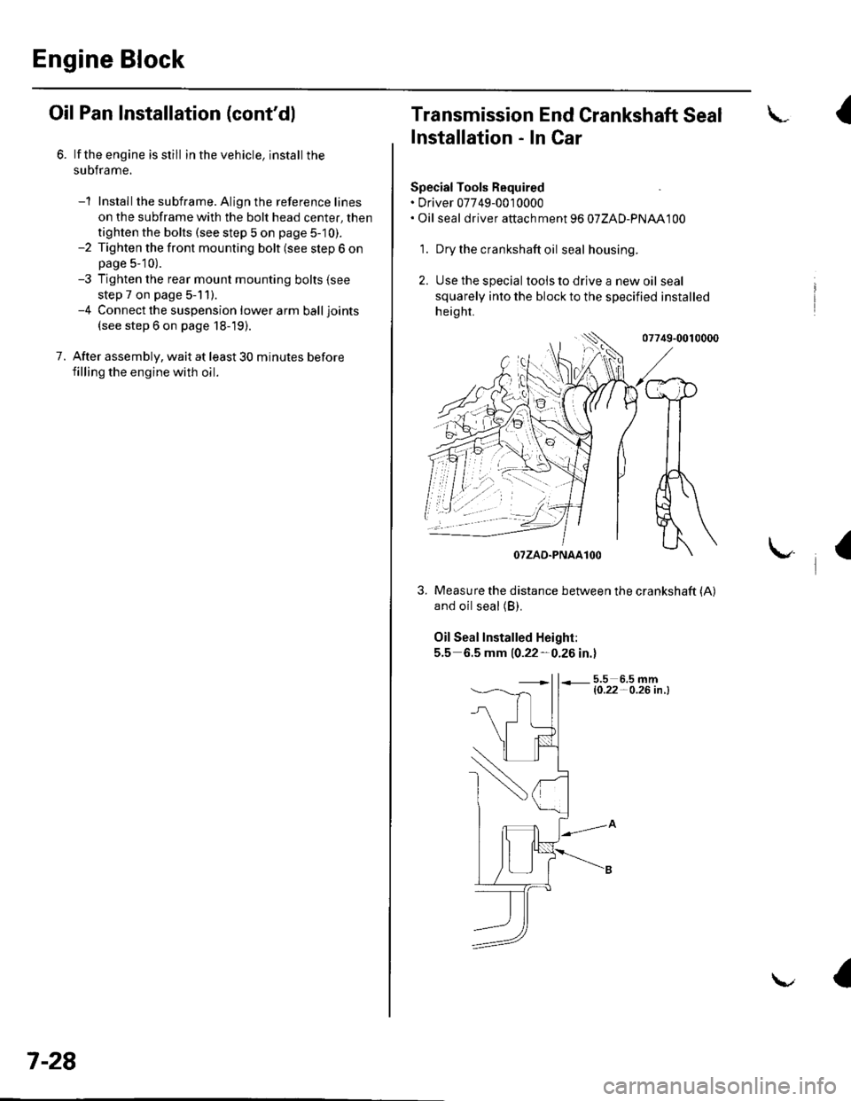
Special Tools Required. Driver 07749-0010000. Oil seal driver attach ment 96 07ZAD-PNAA100
'1. Dry the crankshaft oil seal housing.
2. Use the special tools to drive a new oil seal
squarely into the block to the specified installed
height.
07749-0010000
and oil seal (B).
Oil Seal Installed Height:
5.5 6.5 mm 10.22-0.26 in.l
5.5 6.5 mml0.22- O.26 in .l
I
/$rRfr4T
tr*W(r
-]t
fl\OTZAD.PNAAlOO
Measure the distance between the crankshaft (A)
a
Page 170 of 1139
Engine Lubrication
Oil Pressure Switch Test
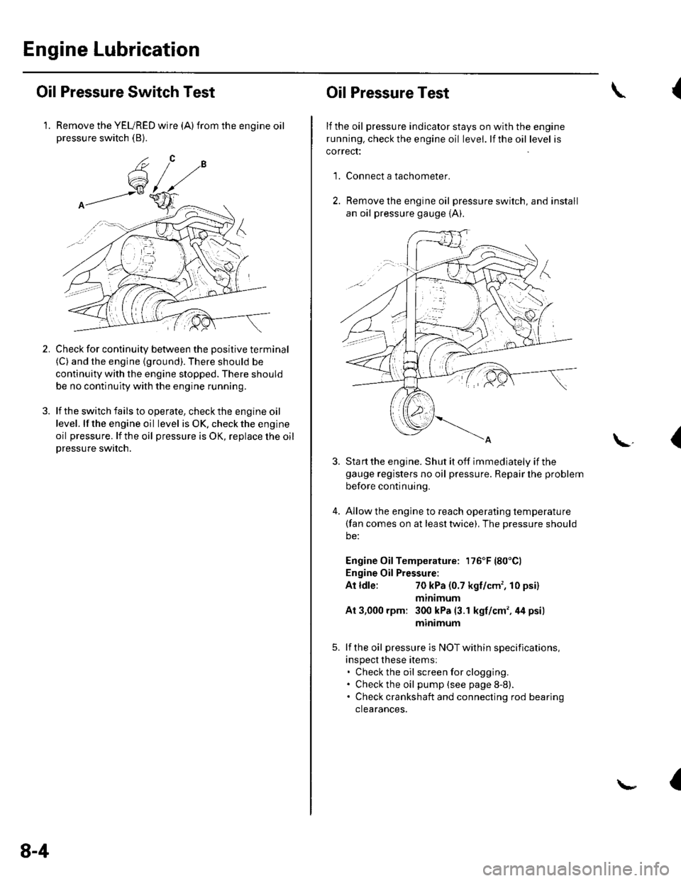
1. Remove the YEURED wire (A)from the engine oilpressure switch (B).
Check for continuity between the positive terminal(C) and the engine (ground). There should be
continuity with the engine stopped. There should
be no continuity with the engine running.
lf the switch fails to operate, check the engine oil
level. lf the engine oil level is OK. check the engine
oil pressure. lf the oil pressure is OK, replace lhe oil
Dressure switch.
2.
8-4
Oil Pressure Test
lf the oil pressure indicator stays on with the engine
running. check the engine oil level. lf the oil level is
correct:
Connect a tachometer.
Remove the engine oil pressure switch, and install
an oil pressure gauge {A).
{
'1.
\.(
4.
Sta rt the engine. Shut it off immediately if thegauge registers no oil pressure. Repair lhe problem
before continuing.
Allow the engine to reach operating temperature(fan comes on at least twice), The pressure should
be:
Engine Oil Temperature: 176'F (80'Cl
Engine Oil Pressure:
At ldle:70 kPa (0.7 kgf/cm', 10 psi)
mtntmum
At 3,000 rpm: 300 kPa (3.1 kgf/cm',44 psi)
minimum
lf the oil pressure is NOT within specifications,
inspect these items:. Check the oil screenforclogging.. Check the oil pump (see page 8-8).. Check crankshaft and connecting rod bearing
clearances.
I
Page 172 of 1139
Engine Lubrication
Engine Oil Filter Replacement
Special Tool Fequired
Oil filter wrench 07HAA-PJ70100
Engine Oil Filter (3/4-turn type)
1. Remove the oil filterwiththesDecial tool.
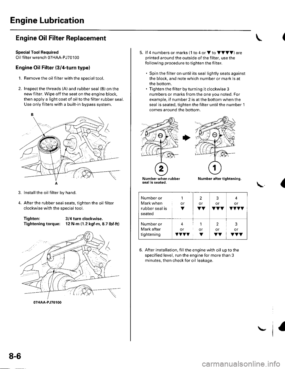
2. Inspect the threads {A) and rubber seal (B) on the
new filter. Wipe off the seat on the engine block,
then apply a light coat of oil to the filter rubber seal.
Use only filters with a built-in bypass system.
Installthe oilfilter by hand.
After the rubber seal seats, tighten the oil filter
clockwise with the special tool.
Tighten: 3/4 turn clockwise.
Tightening torque: 12 N.m (r.2 kgf.m,8.7 lbf.ft)
07HAA-PJ70100
8-6
\,
5. lf 4 numbers or marks (1 to 4 or V to VVVV) are
printed around the outside of the filter, use the
following procedure to tighten the filter.
. Spin the filter on until its seal lightly seats against
the block, and note which number or mark is at
the bottom.. Tighten the filter by turning it clockwise 3
numbers or marks from the one you noted. For
example, if number 2 is at the bottom when the
seal is seated, tighten the filter until the number 1
comes around the bottom.
Number when rubberseal is seated.Number after tightening.
(\..
6. After installation, fill the enginewith oil uptothe
specified level, run the engine for more than 3
minutes, then check for oil leakage.
Number or
Mark when
rubber seal is
1
or
V
2
or
VV
3
or
VVV
4
or
VVVV
Number or
Mark after
tightening
41
or or
vvvv. v
2
or
VV
3
or
VVV
Page 176 of 1139
Engine Lubrication
Oil Pump Overhaul {cont'dl
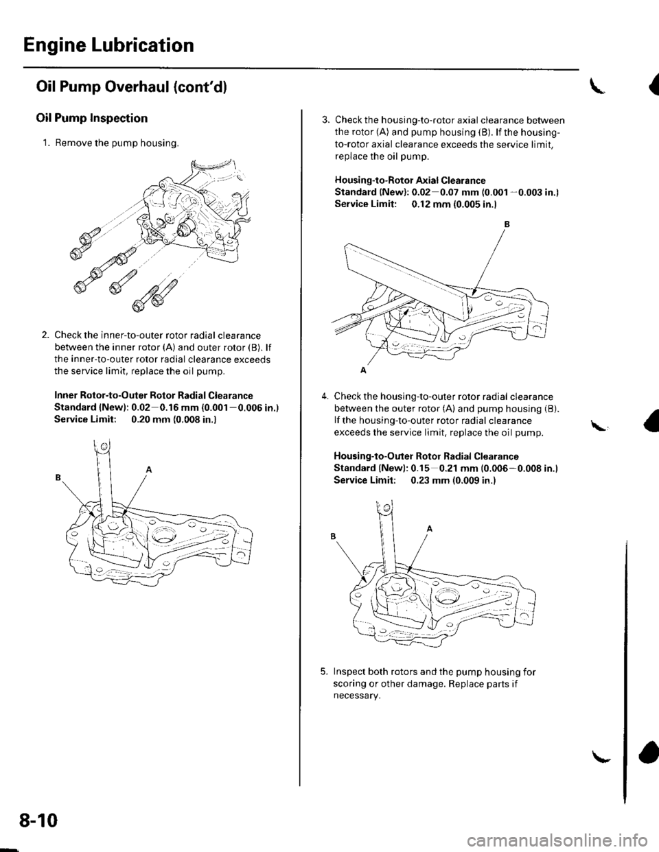
Oil Pump Inspection
1. Remove the pump housing.
Check the inner-to-outer rotor radial clearance
between the inner rotor (A) and outer rotor {B). lf
the inner-to-outer rotor radial clearance exceeds
the service limit, replace the oil pump.
Inner Rotor-to-Outer Botor Radial Clearance
Standard {New): 0.02 0.16 mm (0.001 -0.006 in.)
Service Limit: 0.20 mm (0.008 in.,
1'[1e-\1.-,-2
1 'a - :.: ,-'r'
8-10
\-
{
4.
3. Check th e h ousing-to-roto r axia I clearance between
the rotor (A) and pump housing (B). lf the housing-
to-rotor axial clearance exceeds the service limit.
replace the oil pump.
Housing"to-Rotor Axial Clearance
Standard (New): 0.02 0.07 mm (0.001 -0.003 in.l
Service Limit: 0.12 mm (0.005 in.l
Check the housing-to-outer rotor radial clearance
between the outer rotor (A) and pump housing (B).
lf the housing-to-outer rotor radial clearance
exceeds the service limit, replace the oil pump.
Housing-to-Outer Rotor Radial Clearance
Standard lNewl: 0.15 0.21 mm (0.006-0.008 in.l
Service Limit; 0.23 mm (0.009 in.)
Inspect both rotors and the pump housing for
scoring or other damage. Replace parts if
necessary.
\,
Page 177 of 1139
1.
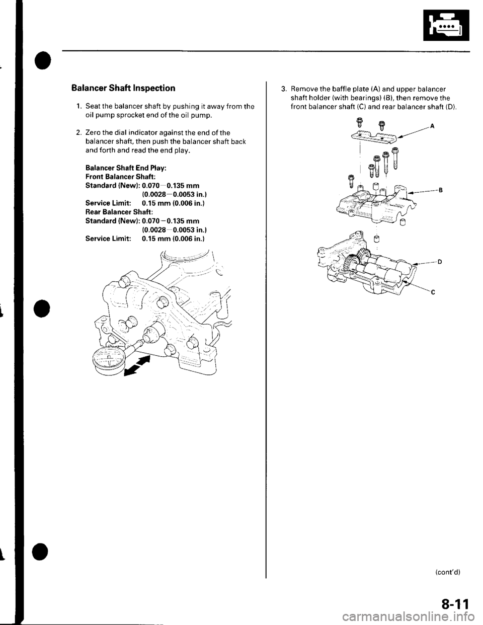
Balancer Shaft Inspection
Seat the balancer shaft by pushing it away from the
oil pump sprocket end ofthe oil pump.
Zero the dial indicator against the end of the
balancer shaft, then push the balancer shaft back
and forth and read the end olav.
Balancer Shaft End Play:
Fronl Balancer Shaft:
Standard {Newl: 0.070 0.135 mm
{0.0028 0.0053 in.}
Service Limit: 0.15 mm (0.006 in.)
Rear Balancer Shaft:
Standard {New): 0.070-0.135 mm(0.0028 0.0053 in.l
Service Limit: 0.15 mm (0.006 in.)
2.
3. Remove the baffle plate (A) and upper balancer
shaft holder {with bearings) (B), then remove the
front balancer shaft (C) and rear balancer shaft (D).
9H.A''/.r L=] j/
R
Rfl|]
3I] UUr Be
+-
(cont'd)
8-11
Page 179 of 1139
8.
9.
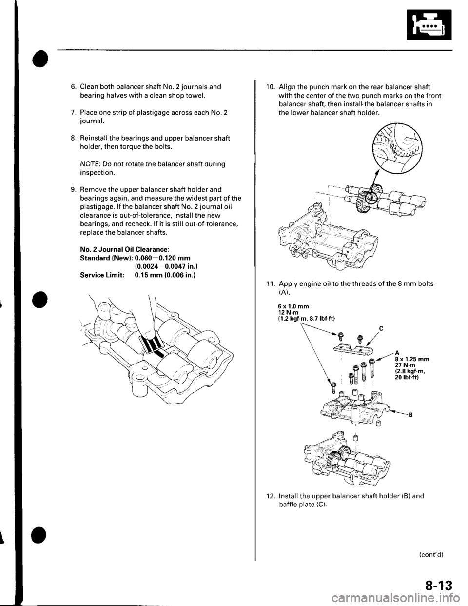
6. Clean both balancer shaft No. 2 journals and
bearing halves with a clean shop towel.
7. Place one strip of plastigage across each No.2journal.
Reinstall the bearings and upper balancer shaft
holder, then torque the bolts.
NOTE; Do not rotate the balancer shaft durinq
insDection.
Remove the uooer balancer shaft holder and
bearings again, and measure the widest part of the
plastigage. lf the balancer shaft No. 2 journal oil
clearance is out-of-tolerance. install the new
bearings, and recheck. lf it is still out-of-tolerance,
replace the balancer shafts.
No. 2 Journal Oil Clearance:
Standard lNewl; 0.060 0.120 mm
Service Limit:
(0.0024 0.0047 in.l
0.15 mm {0.006 in.)
10. Align the punch mark on the rear balancer shaft
with the center of the two punch marks on the front
balancer shaft, then install'the balancer shafts in
the lower balancer shaft holder
Apply engine oil to the threads of the 8 mm bolts(A).
6x1.0mm'12 N.m(1.2 kgt.m, 8.7 lbt ft)
11.
Installthe upper balancer shaft holder (B) and
bafile plate (C).
(cont'd)
12.
8-13
Page 182 of 1139
Engine Lubrication
Oil Pump Overhaul (cont'dl
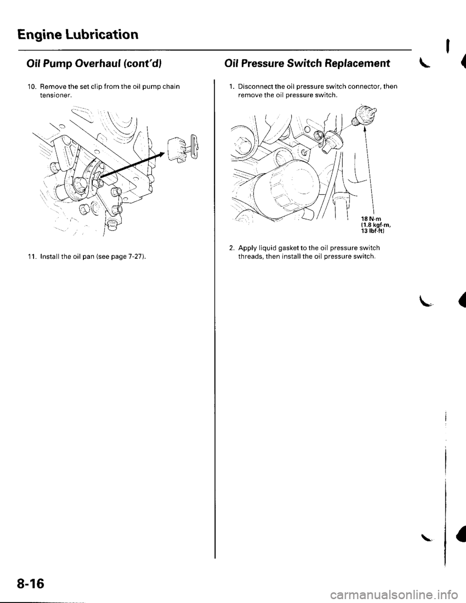
10. Remove the set clip from the oil pumpchain
tensioner.
11. Install the oil pan (see pageT-27).
8-16
\
I
(Oif Pressure Switch Replacement
1. Discon nect the oil pressure switch connector, then
remove the oil pressure switch.
2. Apply liquid gasket to the oil pressure switch
threads, then installthe oil pressure switch.
(
Page 185 of 1139
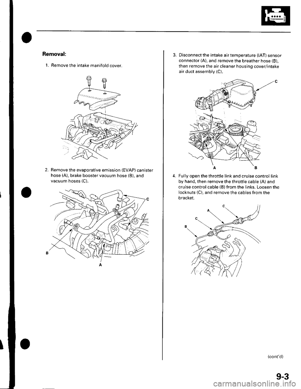
Removal:
'1. Remove the intake manifold cover.
2.Remove the evaporative emission (EVAP) canister
hose (A), brake booster vacuum hose (B), and
vacuum hoses {C).
3. Disconnectthe intake airtemperature (lAT) sensor
connector (A), and remove the breather hose (B),
then remove the air cleaner housing cover/intake
air duct assembly (C).
4.Fully open the throttle link and cruise control link
by hand, then remove the throttle cable (A) and
cruise control cable (B) from the links. Loosen the
locknuts {C). and remove the cables from the
bracket.
(cont'd)
(
9-3
Page 186 of 1139
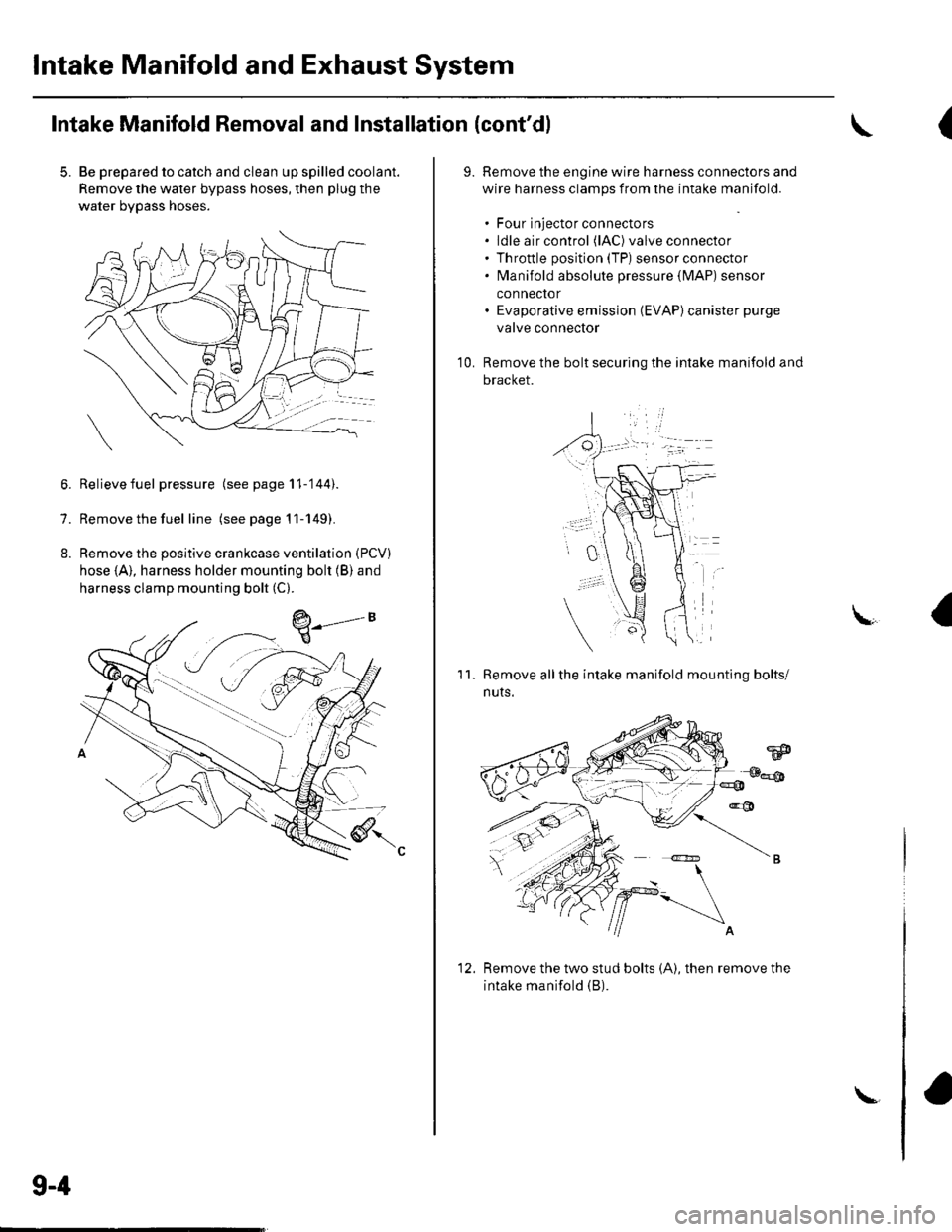
Intake Manifold and Exhaust System
Intake Manifold Removal and Installation (cont'dl
5. Be prepared to catch and clean up spilled coolant.
Remove the water bypass hoses, then plug the
water bypass hoses.
6. Relievefuel pressure (see page 11-'144).
7. Remove the fuel line (seepagell-149).
8. Remove the positive crankcase ventilation (PCV)
hose (A), harness holder mounting bolt (B) and
harness clamp mounting bolt (C).
9-4
\-
(
9.Remove the engine wire harness connectors and
wire harness clamps from the intake manifold.
. Four injector connectors. ldle air control (lAC) valve connector. Throttle position (TP) sensor connector. fvlanifold absolute pressure {lvlAP) sensor
connector. Evaporative emission (EVAP)canister purge
valve connector
Remove the bolt securing the intake manifold and
bracket.
'1 0.
11.Remove allthe intake manifold mounting bolts/
nuts.
Remove the two stud bolts (A), then remove the
intake manifold (B).
1'>