ERS HONDA CIVIC 2003 7.G Workshop Manual
[x] Cancel search | Manufacturer: HONDA, Model Year: 2003, Model line: CIVIC, Model: HONDA CIVIC 2003 7.GPages: 1139, PDF Size: 28.19 MB
Page 609 of 1139
Conventional Brake Components
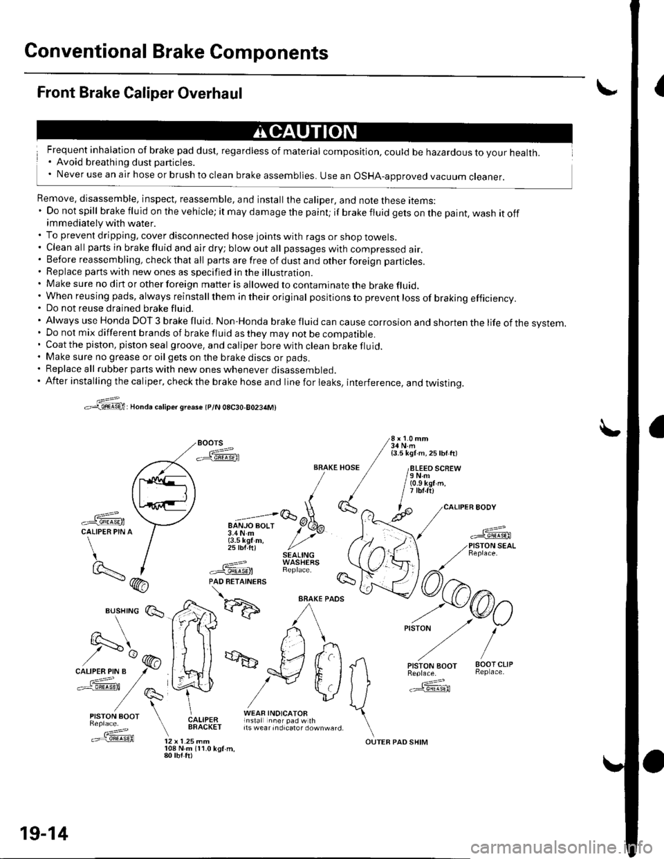
{Front Brake Caliper Overhaul
Frequent inhalation of brake pad dust, regardless of material composition, could be hazardous to your health.. Avoid breathing dust particles.' Never use an air hose or brush to clean brake assemblies. use an osHA-approved vacuum cleaner.
Remove, disassemble, inspect, reassemble, and install the caliper, and note these items:' Do not spill brake fluid on the vehicle; it may damage the paint; if brakefluidgetsonthepaint,washitoffimmediately with water.. To prevent dripping, cover disconnected hose joints with rags or shop towels.. Cleanall partsinbrakefluidandairdry;blowoutall passageswith compressed air.. Before reassembling, check that all parts are free of dust and other foreign particles.. Replace parts with new ones as specified in the illustration.. Make sure no dirt or other foreign matter is allowed to contaminate the brake fluid,' When reusing pads, always reinstallthem in their original pos itio ns to prevent loss of braking efficiency.. Do not reuse drained brake fluid.'AlwaysuseHondaDOT3brakefluid.Non'Hondabrakefluidcancausecorrosionandshortenthelifeofthesvstem.
. Do not mix different brands of brake fluid as they may not be compatible.. Coatthe piston, piston seal groove, and caliper borewithclean brakefluid.. Make sure no grease or oil gets on the brake discs or pads.. Replace all rubber parts with new ones whenever disassembled.. After installing the caliper, check the brake hose and line for leaks, interference, and twistinq.
>:@:Honda caliper sreaso tplN 08C30-80234M)
Boors 3i,l'1.'"
-ffiFA / isli\ii ^ zsw ttt
/paq\tl ll /
,\L,.'iE/ [
-ffi \--l u";;;lqEtCALIPER PIN A / 3.4N.m y' >vr / {3.5 kef m, / ,,' / 25 lbf ft) //'t / SEAL|NG)- I ---=-? WASHEaS
BRAKE HOSE / /8LEEO SCREW/ / /eNm/ / / (o.s kgr'm./ / | itbt.ftl,1(}', ^ l^ /caLl
-ffi \:7 "=;lGoX-
*fL-f
/) I .===? WAStrtXS \t9..- | #.'@ RepracF /7\- (hA PAD RETATNERS !s- / \
*d':ffi
^/rkr) ,-o/
vlJ ffi
Es,lry:' E*,e,a ["fif:i#l1t*"_,,. \.==f@ tz x t.zsmm ourEB paD sHrM
19-14
108 N.m 111.0 kgf.m,80 tbt.ft)
Page 610 of 1139
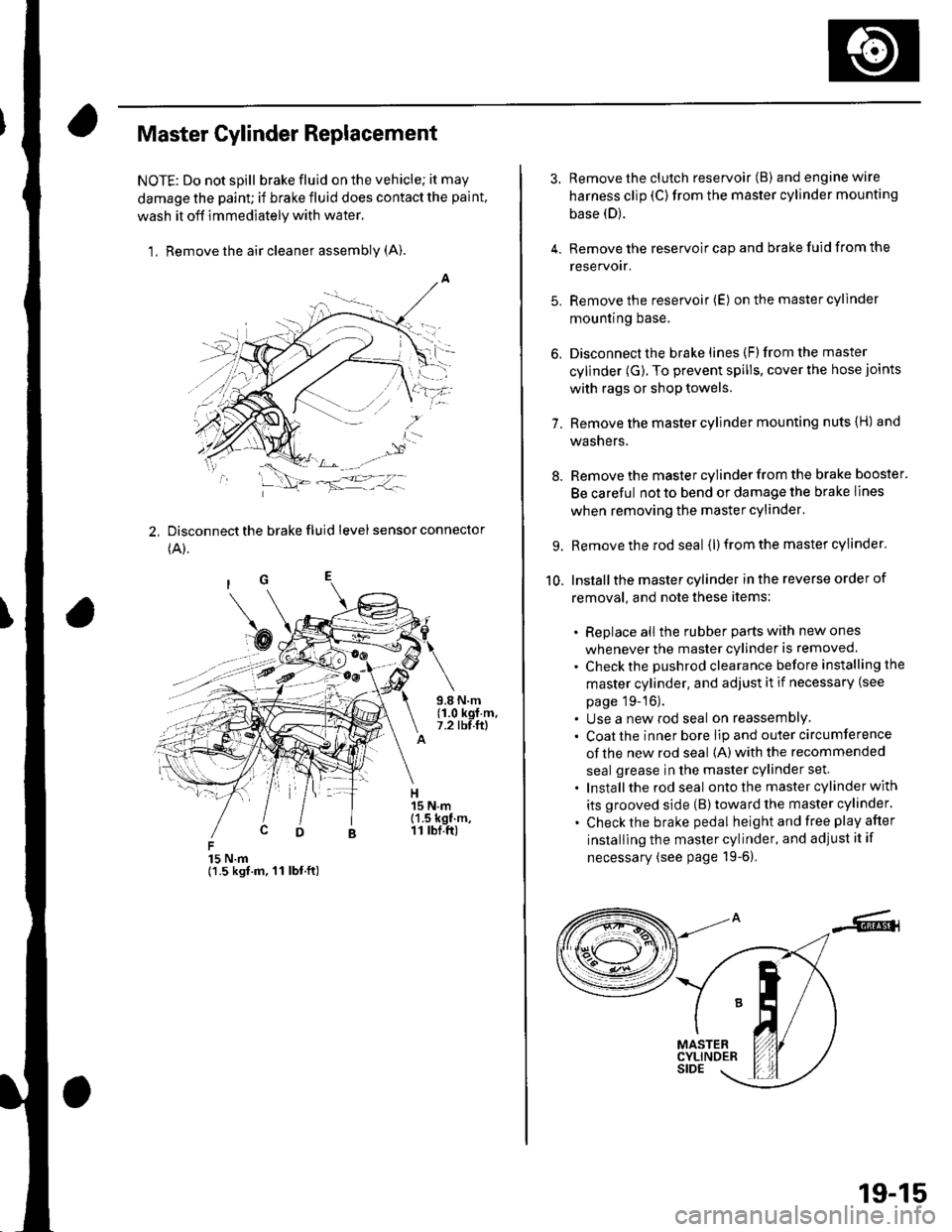
Master Cylinder Replacement
NOTE: Do not spill brake fluid on the vehicle; it may
damage the paint; if brake fluid does contact the paint,
wash it off immediately with water,
1, Remove the air cleaner assembly (A).
2, Disconnect the brake fluid level sensor connector
(A).
15 N.m{1.5 kgt.m, 11 lbt.ft)
3. Remove the clutch reservoir (B) andenginewire
harness clip (C)from the master cylinder mounting
base (D).
4. Remove the reservoir cap and brake fuid from the
reservoir.
5. Remove the reservoir (E) on the master cylinder
mountrng Dase.
6, Disconnect the brake lines (F)from the master
cylinder (G). To prevent spills, cover the hose joints
with rags or shop towels.
7. Remove the master cylinder mounting nuts {H) and
washers.
8. Remove the master cylinder from the brake booster.
Be careful not to bend or damage the brake lines
when removing the master cylinder.
9. Remove the rod seal (l) from the master cylinder.
10. Installthe master cylinder in the reverse order of
removal, and note these items:
. Replace all the rubber parts with new ones
whenever the master cylinder is removed.
. Check the pushrod clearance before installing the
master cylinder. and adjust it if necessary (see
page 19-16).. Use a new rod seal on reassemblY. Coat the inner bore lip and outer circumference
of the new rod seal {A) with the recommended
seal grease in the master cylinder set.
. Installthe rod seal ontothe master cylinder with
its grooved side (B)toward the master cylinder.
. Check the brake pedal height and free play after
installing the master cylinder, and adjust it if
necessary (see page 19-6).
19-15
Page 613 of 1139
Gonventional Brake Components
IBrake Booster Test
Functional Test
1. With the engine stopped, press the brake pedal
several times to deplete the vacuum reservoir, thenpress the pedal hard, and hold itfor 15 seconds. lfthe pedal sinks, either the master cylinder is
bypassing internally, or the brake system (master
cylinder, lines. modulator, or calipers) is leaking.
2. Start the engine with the brake pedal pressed. lf thepedal sinks slightly, the vacuum booster is workingproperly. lf the pedal height does not vary, thebooster or check valve is faulty.
3. With the engine running, press the brake pedal
lightly. lfthe brake pedal sinks more than 1O mm
{3/8 in, ) in 3 minutes, the master cylinder is faulty.A slight change in pedal height when the Ay'C
compressor cycles on and off is normal. (The A,/C
compressor load changes the vacuum available tothe booster.)
Leak Test
1. Press the brake pedal with the engine running, thenstop the engine. lf the pedal height does not vary
while pressed for 30 seconds, the vacuum boosteris OK. lf the pedal rises, the booster is faulty.
2. With the engine stopped, press the brake pedal
several times using normal pressure. When thepedal is first pressed, it should oe row.
On consecutive applications, the pedal height
should gradually rise. lfthe pedal position does notvarv, check the booster check valve.
19-18
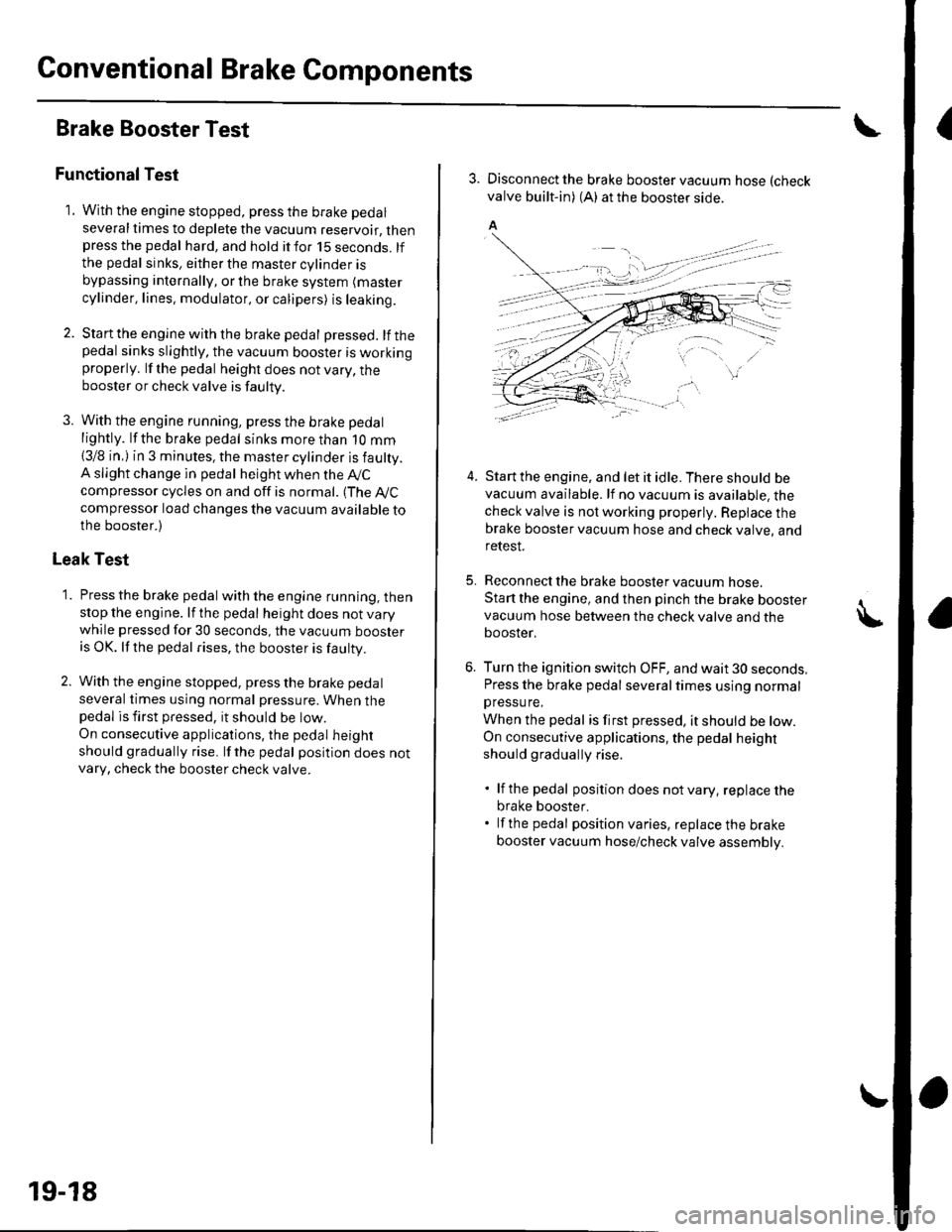
3. Disconnect the brake booster vacuum hose (check
valve built-in) (A) at the booster side.
5.
4.Start the engine, and let it idle. There should bevacuum available. lf no vacuum is available, thecheck valve is not working properly. Repiace thebrake booster vacuum hose and check valve, andrelesI.
Reconnect the brake booster vacuum nose.
Start the engine, and then pinch the brake boostervacuum hose between the check valve and thebooster,
Turn the ignition switch OFF, and wait 30 seconds,Press the brake pedal several times using normalpressu re,
When the pedal is first pressed, it should be low.On consecutive applications, the pedal height
should gradually rise.
. lf the pedal position does notvary, replacethe
brake booster.. lf the pedal position varies, replace the brake
booster vacuum hose/check valve assembly.
Page 614 of 1139
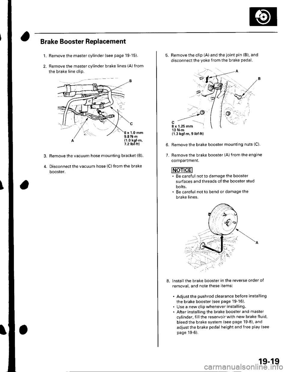
Brake Booster Replacement
1.Remove the master cylinder (see page 19-15).
Remove the master cylinder brake lines {A) from
the brake line clip.
c
6x1.0mm9.8 N.m(1.0 kgf.m,7.2 tbf.ft)
Remove the vacuum hose mounting bracket (B).
Disconnect the vacuum hose {C) from the brake
booster.
'-/
.,.,....
alu
i '..
5. Remove the clip (A) and the joint pin (B). and
disconnectthe yoke from the brake pedal.
7.
{'l.3 kgf.m,9 lbf.ftl
Remove the brake booster mounting nuts (C).
Remove the brake booster (A)from the engine
comparlmenr.
INdAdEI. Be careful not to damage the booster
surfaces and threads of the booster stud
bolts.. Be careful not to bend or damage the
brake lines.
lnstallthe brake booster in the reverse order of
removal, and note these items:
. Adjust the pushrod clearance before installing
the brake booster (see page 19-16).. Use a new clip whenever installing.. After installing the brake booster and master
cylinder, fill the reservoir with new brake fluid,
bleed the brake system (see page 19-8), and
adjust the brake pedal height and free play (see
page 19-6),
19-19
Page 616 of 1139
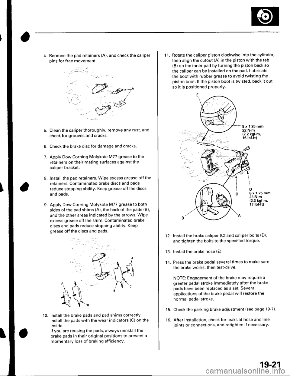
4. Remove the pad retainers (A). and check the caliper
pins for free movement.
:.i _ _l
7.
8.
5. Clean the caliper thoroughly; remove any rust. and
check for grooves and cracks.
6, Check the brake disc for damage and cracks.
Apply Dow Corning Molykote M77 grease to the
retainers on their mating surfaces against the
caliper bracket,
Installthe pad retainers. Wipe excess grease offthe
retainers. Contaminated brake discs and pads
reduce stopping ability. Keep grease off the discs
and pads.
Apply Dow Corning Molykote lvl77 grease to both
sides of the pad shims {A), the back of the pads (B),
and the other areas indicated by the arrows. Wipe
excess grease off the shim. Contaminated brake
discs and pads reduce stopping ability. Keep
grease off the discs and pads.
9.
..-.
10. Installthe brake pads and pad shims correctly.
Installthe pads wirh the wear indicators {C) on the
inside.
lf you are reusing the pads, always reinstall the
brake pads in their original positions to prevent a
momentary loss of braking efficiency.
11. Rotate the caliper piston clockwise into the cylinder,
then align the cutout (A) in the piston with the tab
{B) on the inner pad by turning the piston back so
the caliper can be installed on the pad. Lubricate
the boot with rubber grease to avoid twisting the
Diston boot. lf the piston boot is twisted, back it out
so it is positioned properly.
8 x 1.25 mm22 N.ml2.2 kgt m,16 rbl.ttl
.ar
D8 x 1.25 mm23Nm{2.3 kgf.m,17 rbf.ft)
13.
14.
Installthe brake caliper (C) and caliper bolts (D).
and tighten the bolts to the specified torque.
Installthe brake hose (E).
Press the brake pedal several times to make sure
the brake works, then test-drive.
NOTE: Engagement of the brake may require a
greeter pedal stroke immediately after the brake
pads have been replaced as a set. Several
applications of the brake pedal will restore the
normal pedal stroke,
15. Check the parking brake adjustment {see page 19-7).
16. After installation, check for leaks at hose and line
joints or connections, and retighten if necessarY.
19-21
Page 617 of 1139
Conventional Brake Components
Rear Brake Disc Inspection
Runout
1. Raise the rear of the vehicle, and support it with
safety stands in the proper location (see page 1-8).Remove the rear wheels,
2. Remove the brake pads (see page 19-20).
3. Inspect the disc surface for damage and cracks.
Clean the disc thoroughly, and remove all rust,
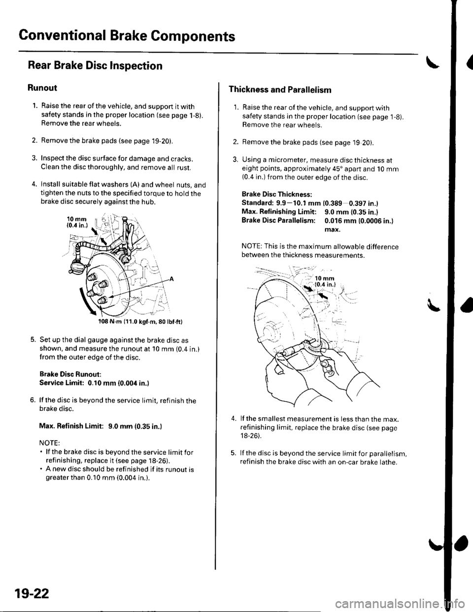
4. lnstall suita ble f lat washers (A) and wheel nuts, andtighten the nuts to the specified torque to hold thebrake disc securely against the hub.
108 N.m (11.0 kgf.m,80lbf.ft)
Set up the dial gauge against the brake disc as
shown. and measure the runout at 10 mm (0.4 in.)
from the outer edge of the disc.
Brake Disc Runout;
Service Limit: 0.10 mm {0.004 in.)
lf the disc is beyond the service limit, refinish thebrake disc.
Max. Refinish Limit: 9.0 mm (0.35 in.)
NOTE:. lf the brake disc is beyondtheservice limitfor
refinishing, replace it (see page 18-26).. A new disc should be refinished if its runout isgreater than 0.10 mm (0.004 in.).
19-22
Thickness and Parallelism
1. Raise the rear of the vehicle, and support with
safety stands in the proper location (see page l-g).Remove the rear wheels.
2. Remove the brake pads {see page 19 20).
3, Using a micrometer, measure disc thickness ateight points, approximately 45'apart and 10 mm
{0.4 in.) from the outer edge of the disc.
Brake Disc Thickness:
Standard: 9.9-10.1 mm (0.389 0.397 in.l
Max. Retinishing Limit: 9.0 mm (0.35 in.)
Brake Disc Parallelism: 0.016 mm 10.0006 in.)
max.
4.lf the smallest measurement is less than the max.
refinishing limit, replace the brake disc (see page
18-26).
lf the disc is beyond the service limit for parallelism,
refinish the brake disc with an on-car brake lathe.
Page 618 of 1139
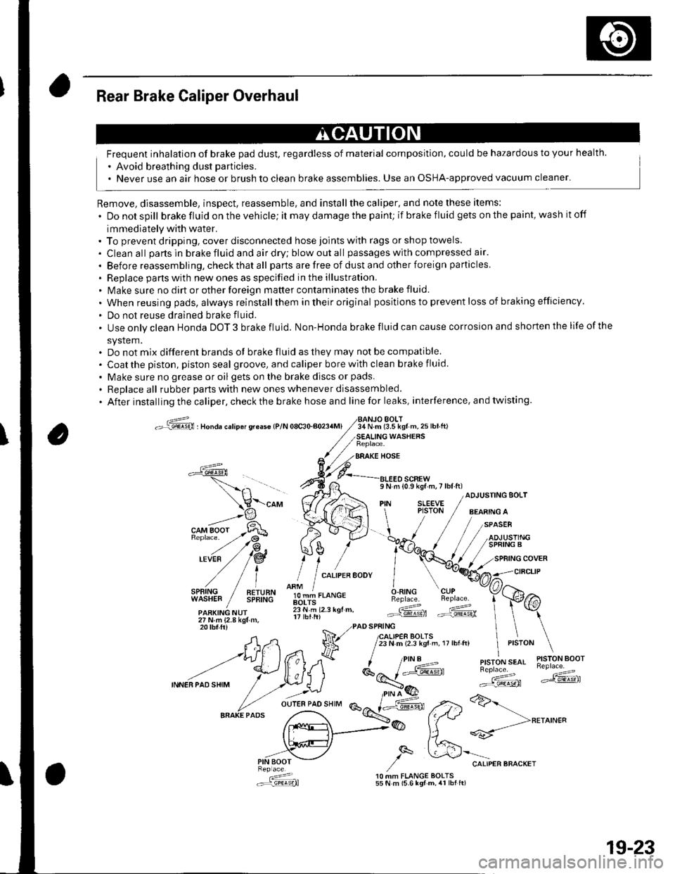
Rear Brake Caliper Overhaul
Frequent inhalation of brake pad dust, regardless of material composition, could be hazardous to your health.
' Avoid breathing dust particles.
. Never use an air hose or brush to clean brake assemblies. Use an OSHA-approved vacuum cleaner'
Remove, disassemble, inspect, reassemble, and installthe caliper, and note these items:
. Donotspill brake fluid on the vehicle; it may damage the paint; if brake f luid gets on the paint, wash it off
immediately with water.. To prevent dripping. cover disconnected hose joints with rags or shop towels.
. Cleanall partsinbrakefluidandairdry;blowoutall passageswith compressed air'
. Before reassembling, check that all parts are free of dust and other foreign particles
. Replace pans with new ones as specified in the illustration.. Make sure no dirt or other foreign matter contaminates the brake fluid.
. When reusing pads, always reinstallthem in their original positions to prevent loss of b ra king efficie ncy.
. Do not reuse drained brake fluid.
. Use only clean Honda DOT 3 brake fluid. Non-Honda brake fluid can cause corrosion and shorten the life of the
system.. Do not mix different brands ot brake fluid as they may not be compatible.
. Coatthe piston, piston seal groove, and caliper bore with clean brake fluid.
. Make sure no grease or oil gets on the brake discs or pads.
. Replaceall rubber parts with new ones whenever disassembled.
. After installing the caliper, check the brake hose and line for leaks, interference. and twisting.
oG , nonau."rip6r qreas€ lP/N 08c30-aoa4Ml34 N.m (3.5 kgf m,25lbtft)BOLT
WASHERS
BRAKE HOSE
a
l,i,,'IltE" / !!;,ff
olT-J,.o"c.O.RING CUPBeplace. Beplace.
.ARKING NUr lii.'i rz.r rgr.. Gd ffi27Nm{2.8kgtm,
\-"o, V((rA ",1 ;[.,.JF /;;;;---
t H\a \l / t,i*t'*"
?,,.t/*"^.,,.:,"", /"V4#
ADJUSTING BOLT
,/
27Nm{2.8kgf.m,20 tbf.ftr PAD SPRING
A,n Na 7lfl,lif,loffi ',,0,n, ,,:,o" \
--t)(*ff l^7k ''"'t!1'ry#'
INNEBPA'SHIM
/ .r.:._U i*E'( ":;*" *dF ,.2>a>-
fr.x{_>@ fftt **-->**^'"
,,.-"iV ,/q &'"o.,"."""o"^.,
: 10 MM FLANGE BOLTS.:r=,9!q!q}l 55 N m (5.6 lgf-m, 4r lbt ft)
19-23
Page 620 of 1139
Brake Hose Replacement
NOTE:. Do not spill brake fluid on the vehicle; it may damage
the paint; if brake fluid gets on the paint, wash it off
immediately with water.. To prevent dripping, cover disconnected line joints
with rags or shop towels.. Before reassembling, check that all parts are free of
dust and other foreign particles.
. Replace parts with new ones whenever specified to
do so.
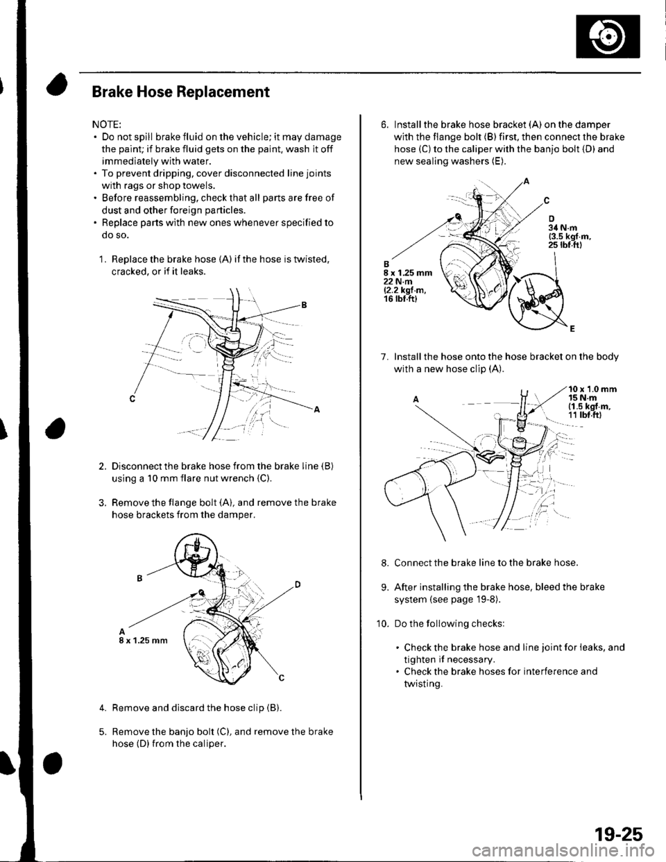
1 . Replace the brake hose (A) if the hose is twisted,
cracked, or if it leaks.
Disconnect the brake hose from the brake line (B)
using a 10 mm flare nut wrench {C)
Remove the flange bolt (A), and remove the brake
hose brackets from the damper.
Remove and discard the hose clip (B).
Remove the banjo bolt (C), and remove the brake
hose (D) {rom the caliper.
4.
I x 1.25 mm
6. Installthe brake hose bracket (A)on the damper
with the flange bolt (B) first, then connect the brake
hose (C) to the caliper with the banjo bolt {D) and
new sealing washers (E).
7. lnstallthe hose onto the hose bracket on the bodv
with a new hose clip (A).
10 x 1.0 mm15 N.mi (1.5 kgf.m,
! 1t tbt.ftl
Connect the brake line to the brake hose.
After installing the brake hose, bleed the brake
system (see page l9-8).
Do the following checks:
. Check the brake hose and line joint for leaks, and
tighten if necessary.. Check the brake hoses for interference and
twisting.
9.
10.
19-25
Page 622 of 1139
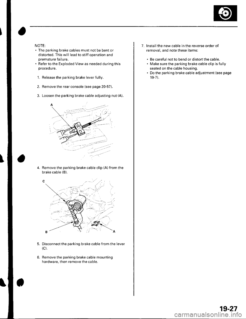
NOTE:. The parking brake cables must not be bent or
distorted. This will lead to stiff operation and
premature failure.. Refer to the Exploded View as needed during this
proceoure.
1. Release the parking brake lever fully.
2. Remove the rear console (see page 20-57).
Remove the parking brake cable clip (A) from the
brake cable (B).4.
6.
Disconnectthe parking brake cable from the lever
{c).
Remove the parking brake cable mounting
hardware, then remove the cable.
7. lnstallthe new cable in the reverse order of
removal. and note these items:
. Be careful not to bend or distort the cable.. Make sure the parking brake cable clip is fully
seated on the cable housing.. Do the parking brake cable adjuslment (see page
19-7 ).
19-27
Page 653 of 1139
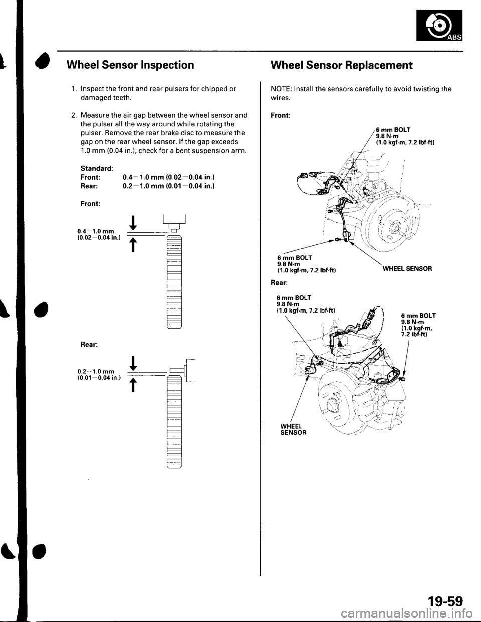
Wheel Sensor Inspection
1.
2.
Inspect the front and rear pulsers for chipped or
damaged teeth.
Measure the air gap between the wheel sensor and
the pulser all the way around while rotating the
pulser. Remove the rear brake disc to measure the
gap on the rear wheel sensor. lf the gap exceeds
1.0 mm (0.04 in.), check for a bent suspension arm.
Standard:
Front; 0.4- 1.0 mm (0.02-0.04 in.)
Rear: 0.2 1.0 mm (0.01 0.04 in.l
Front:
0.4 '1.0 mm10.02 0.0'l in.l
I
t
Bear:
0.2 1.0 mm{0.01 0.04 in.}
Wheel Sensor Replacement
NOTE: Inslall the sensors carefully to avoid twisting the
wtres.
Front:
6 mm BOLT9.8 N.m{1.0 kgf.m,7.2lbf.ftl
6 mm BOLT9.8 N.m{1.0 kgf.m,7.2 lbf.ftl
Rear:
6 mm BOLT9.8 N.m11.0 kgf.m,7.2 lbf.ft)
WHEEL SENSOR
6 mm BOLT9.8 N.m(1.0 kgf'm,7.2 rbr.ft)
19-59