Compressor HONDA CIVIC 2003 7.G User Guide
[x] Cancel search | Manufacturer: HONDA, Model Year: 2003, Model line: CIVIC, Model: HONDA CIVIC 2003 7.GPages: 1139, PDF Size: 28.19 MB
Page 161 of 1139
Piston Installation
lf the crankshaft is already installed
1. Setthe crankshaftto bottom dead center (BDC) for
each cylinder.
2. Remove the connecting rod caps, then install the
ring compressor, and check that the bearing is
securely in place,
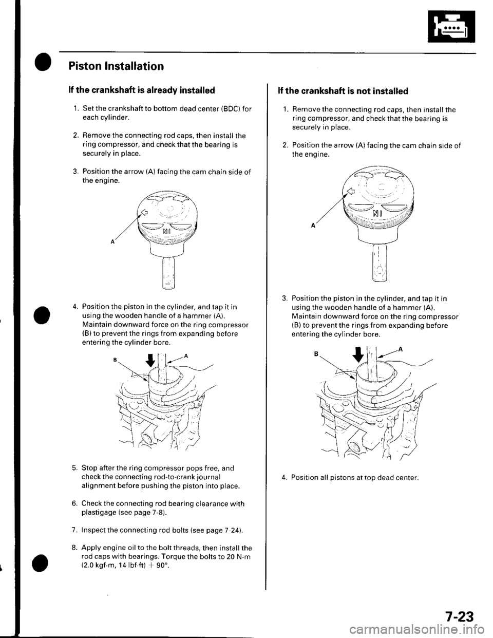
3. Position the arrow {A) facing the cam chain side of
rne engtne.
Position the piston in the cylinder, and tap it in
using the wooden handle of a hammer (A).
N4aintain downward force on the ring compressor(B) to prevent the rings from expanding before
entering the cylinder bore.
Stop after the ring compressor pops free, and
check the connecting rod-to-crank journal
alignment before pushing the piston into place.
Check the connecting rod bearing clearance withplastigage (see page 7-8).
lnspect the connecting rod bolts (see page 7 241.
Apply engine oil to the bolt threads, then install the
rod caps with bearings. Torque the bolts to 20 N.m
{2.0 kgf m, 14 lbf ft) + 90'.
6.
7.
2.
1.
lf the crankshaft is not installed
Remove the connecting rod caps. then install the
ring compressor, and check that the bearing is
securely in place.
Position the arrow (A)facing the cam chain side of
Ine engrne.
Position the piston in the cylinder, and tap it in
using the wooden handle of a hammer (A),
Maintain downward force on the ring compressor(B) to prevent the rings from expanding before
entering the cylinder bore.
4. Position all pistons attop dead center.
\--lno n\-.--l. ^u t
>-*/zi
.,.'_\pf{
wr
(( 'V,/ :
7-23
Page 229 of 1139
![HONDA CIVIC 2003 7.G User Guide Fuel and Emissions Systems
System Descriptions (contdl
ECM lnputs and Outputs at Connector E (31P}
L
u
1iMoFPR
2sr-{]zs3LG34SG3
6$1025HTC
1M RLY
8AFSHTCR
I
14FTP15ELD
16EPSLD
18ACC20Z/VBS21VSV
22BKSW HONDA CIVIC 2003 7.G User Guide Fuel and Emissions Systems
System Descriptions (contdl
ECM lnputs and Outputs at Connector E (31P}
L
u
1iMoFPR
2sr-{]zs3LG34SG3
6$1025HTC
1M RLY
8AFSHTCR
I
14FTP15ELD
16EPSLD
18ACC20Z/VBS21VSV
22BKSW](/img/13/5744/w960_5744-228.png)
Fuel and Emissions Systems
System Descriptions (cont'dl
ECM lnputs and Outputs at Connector E (31P}
L
u
1iMoFPR
2sr-{]zs3LG34SG3
6$1025HTC
1M RLY
8AFSHTCR
I
14FTP15ELD
16EPSLD
18ACC20Z/VBS21VSV
22BKSW23K-LINE24SEFMJ26NEP
21rMoCD
29scs30WEN31MIL
Wire side of female terminals
NOTE: Standard battery voltage is '12 V.
TerminalnumberWire colorferminal nameDescription Signal
GRNI/ELIMO FPR (IMMOBILIZERFLJEL PUMP RELAYIDrives PGM Fl main relay 20Vfor2 seconds after turning ignition switch ON{ll). then batterv voltaoe2WHT/REDSHO2S (SECONDARYHEATED OXYGEN SENSOR(SECONDARY HO2S),SENSOR 2r
Detects secondary HO2S{sensor 2) signalWith throttle Jully opened from idle with fullywarmed up engine: above 0.6VWith throttle quickly closed: below 0.4 V
3BRN/YELLG3 (LOGIC GROUND)cround forthe ECM/PCMcontrolcircuitLess than 1.0 V at all times
4PNKSG3 {SENSOR GBOUND)Sensor oroundLess than 1.0 V at all times5YEUELUVCC3 {SENSOR VOLTAGE)Provides sensor voltageWith ignition switch ON (ll): about 5 VWith ionition switch OFF: about 0 V6BLKATr'HTSO25HTC (SECONDARYHEATED OXYGEN SENSOR(SECONDARY H02S)HEATER CONTROL)
Drives secondary HO2SheaterWith ignition switch ON (ll): baftery voltageWilh fullv warmed up engine running: dul,controlled
1REDA/ELMRLY (PGM.FI MAINRELAY}Drives PGM-Flmain relay 1Power source forthe DTCWith ignition switch ON (ll): about 0 VWith ignition switch OFF: battery voltage
IORNAFSHTCR {AIR FUEL BATIO(Iy'F)SENSOR HEATERCONTROL RELAY)
Drives air fuel ratio sensorheater relayWith ignition swirch ON {ll): 0 V
IYEUBLKIGl (IGNITION SIGNAL)Detecrs ignition signalWith ignition switch ON (ll): battery voltageWith iqnition switch OFF: about 0 V't4LT GRNFIP lFUEL TANKPRESSURE (FTP) SENSOR)Detects FTP sensor signalWith ignition switch ON (ll) and fuel fill cap open:about 2.5 VGRN/REDELD (ELECTRICAL LOADDETECTOF)Detects ELD signalWith ignition swjtch ON itt):aOoutO.t V l-gV(deDendino on electrical load)LT GRN/8LKEPSLD (ELECIRICALPOWEB STEEBING LOADDETECT)
Detects Power steering loadsrgnalAt idle with steering wheel in straight aheadposition: about 0 VAt idle with steering wheelatfull lock: momentary
'18REDACC (Ay'C CLUTCH RELAY)Drives P,/C clutch relayWith compressor ON: about 0 VWith comoressor OFF: batterv voltaoe
11-22
\-
Page 233 of 1139
Fuel and Emissions Systems
System Descriptions (cont'd)
PGM-FI System
The Programmed Fuel Injection (PGM-Fl) system is a
sequential multiport fuel injection system.
Air Conditioning {A/C) Compressor Glutch Relay
When the ECfM receives a demand for cooling from the
Ay'C system, it delays the compressor from being
energized, and enriches the mixture to assure smooth
transition to the AVC mode.
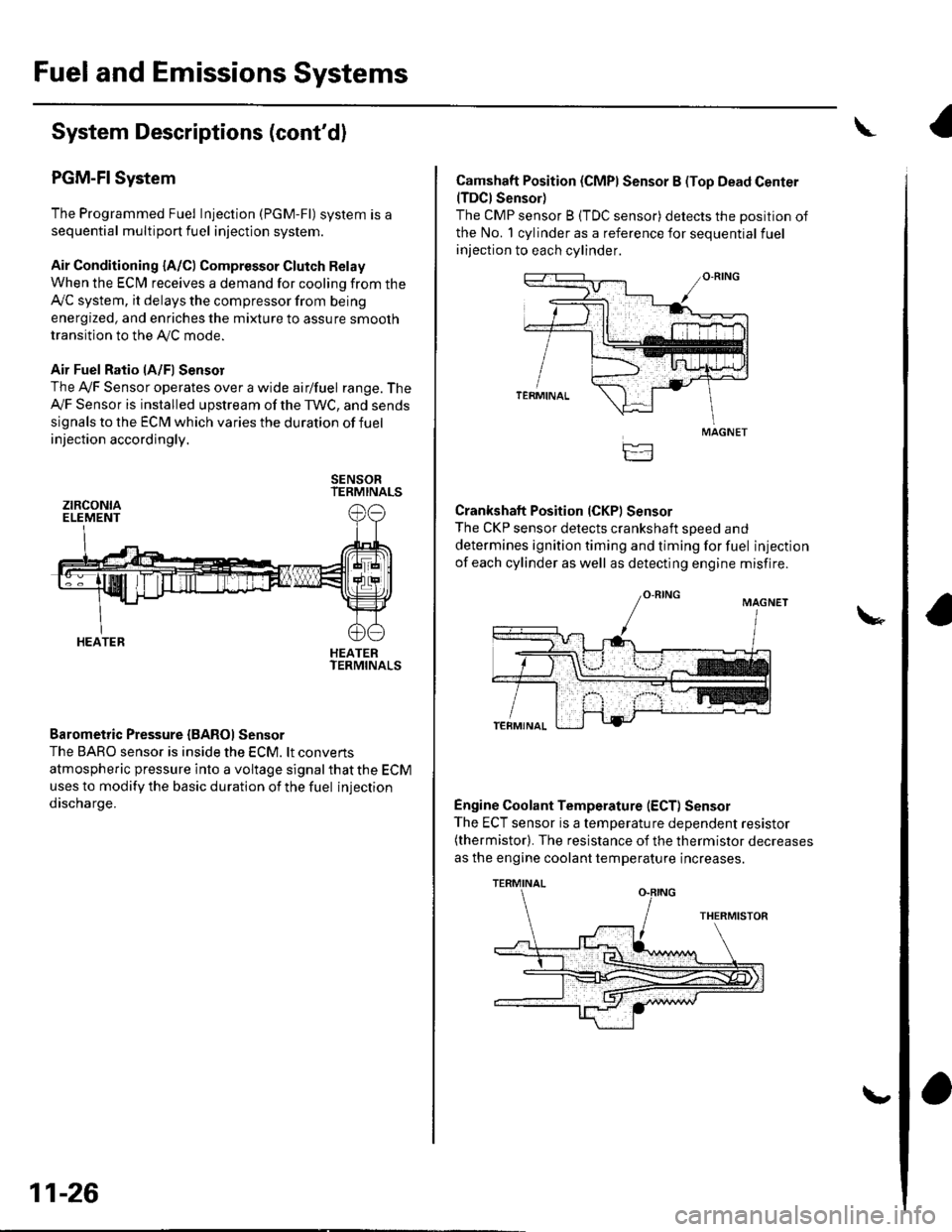
Air Fuel Ratio lA/Fl Sensor
The Ay'F Sensor operates over a wide airlfuel range. The
Ay'F Sensor is installed upstream of the TWC, and sends
signals to the ECM which varies the duration of fuel
injection accordingly.
SENSORTERMINALS
HEATERTERMINALS
Barometric Pressure {BAROI Sensor
The BARO sensor is inside the ECM. lt convens
atmospheric pressure into a voltage signal that the ECM
uses to modify the basic duration of the fuel injection
discharge.
ztRcoNtaELEMENT
HEATER
11-26
\,
Camshaft Position (CMPI Sensor B (Top Dead Center(TDCI Sensor)
The CMP sensor B (TDC sensor) detects the position of
the No. 1 cylinder as a reference for sequential fuel
injection to each cylinder.
Crankshaft Position (CKPI Sensor
The CKP sensor detects crankshaft soeed and
determines ignition timing and timing for fuel injection
of each cylinder as well as detecting engine misfire.
Engine Coolant Temperature (ECT) Sensor
The ECT sensor is a temperature dependent resistor(thermistor). The resistance of the thermistor decreases
as the engine coolant temperature increases.
MAGNET
TERMINAL
Page 239 of 1139
Fuel and Emissions Systems
(
{
System Descriptions (cont'd)
ldle Control System
When the engine is cold, the Ay'C compressor is on, the
transmission is in gear, the brake pedal is pressed. thepower steering load is high, or the alternator is
charging, the ECIM controls current to the ldle Air
Control (lAC) valve to maintain the correct idle speed.
Refer to the System Diagram to see the functional
layout of the system.
Brake Pedal Position Switch
The brake pedal position switch signals the ECM when
the brake pedal is oressed.
Electrical Power Steering (EPS) Senser
The EPS sensor signals the ECM when the power
steering load is high.
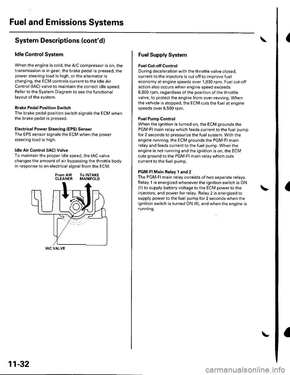
ldle Air Control llACl Valve
To maintain the proper idle speed, the IAC valve
changes the amount of air bypassing the throttle body
in response to an electrical signal from the ECM.
From AIR To INTAKECLEANER MANIFOLD
IAC VALVE
11-32
Fuel Supply System
Fuel Cut-off Control
During deceleration with the throttle valve closed,
current to the injectors is cut off to improve fuel
economy at engine speeds over 1,030 rpm. Fuel cut-off
action also occurs when engine speed exceeds
6,900 rpm, regardless of the position of the throttle
valve, to protect the engine from over-rewing. When
the vehicle is stopped. the ECM cuts the fuel at engine
speeds over 6,500 rpm.
Fuel Pump Control
When the ignition is turned on, the ECM grounds the
PGM-Fl main relay which feeds current to the fuel pump
for 2 seconds to pressurize the fuel system, With the
engine running. the ECM grounds the PGM-Fl main
relay and feeds current to the fuel pump. When the
engine is not running and the ignition is on, the ECI\4
cuts ground to the PGM-Fl main relay which cuts
current to the fuel pump.
PGM-FI Main Relay 1 and 2
The PGM-Fl main relay consists of two separate relays.
Relay 1 is energized whenever the ignition switch is ON(ll) to supply battery voltage to the ECM power to the
injectors, and power for relay, Relay 2 is energized to
supply power to the fuel pump for 2 seconds when the
ignition switch is turned ON (ll), and when the engine is
runnrng.
Page 340 of 1139
A/G Signal Circuit Troubleshooting
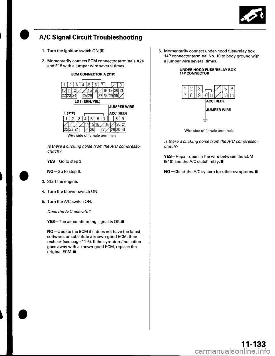
Turn the ignition switch ON (ll).
Momentarily connect ECM connector terminals 424
and E18 with a jumper wire several times.
1.
2.
5.
Wire side of female terminals
ls there a clicking noise I rom the NC compressor
clutch?
YES Go to step 3.
NO-Go to step 6.
Sta rt the engine.
Turn the blower switch ON.
Turn the Ay'C switch ON.
Does the NC operate?
YES-The air conditioning signal is OK.I
NO Update the ECM if it does not have the latest
software, or substitute a known-good ECM. then
recheck (see page 11-6). lf the symptom/indication
goes away with a known-good ECM, replace the
original €CM.l
6. Momentarily connect under-hood tuse/relay box
14P connector terminal No. 10 to body ground with
a jumper wire several times.
UNDER.HOOD FUSE/RELAY BOXI4P CONNECTOR
12356
1891011IJ14
ACC (RED)
JUMPER WIRE
Wire side of female terminals
ls there a clicking noise f rom the NC compressor
clutch?
YES- Repair open in the wire between the ECM(E'18) and the Ay'C clutch relay.l
NO- Check the A/C system for other symptoms.l
11-133
Page 580 of 1139
Front Suspension
Damper/Spring Replacement (cont'd)
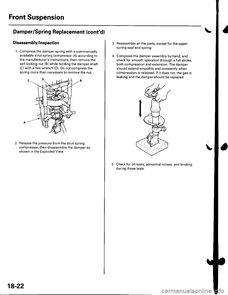
Disassembly/lnspection
1. Compress the damper spring with a commercially
available strut spring compressor (A) according to
the manufacturer's instructions. then remove the
self-locking nut (B)while holding the damper shaft(C) with a hex wrench (D). Do not compress the
spring more than necessary to remove the nut,
Release the pressure from the strut spring
compressor, then disassemble the damper as
shown in the Exploded View.
18-22
4.
Reassemble all the pans, except for the upper
spring seat and spring.
Compress the damper assembly by hand, and
check for smooth operation through a full stroke.
both compression and extension. The damper
should extend smoothly and constantly when
compression is released. lf it does not, the gas is
leaking and the damper should be replaced.
Check for oil leaks, abnormal noises, and binding
during these tests.
\
Page 582 of 1139
Front Suspension
Damper/Spring Replacement (cont'dl
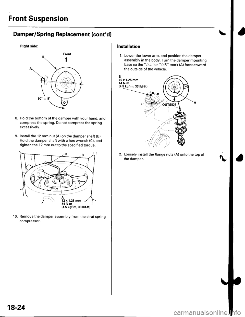
Right side:
9.
Hold the bottom of the damper with your hand, and
compress the spring. Do not compress the spring
excessively.
Installthe 12 mm nut (A) on the damper shaft (B).
Hold the damper shaft with a hex wrench (C), and
tighten the 12 mm nut to the specified torq ue.
(4.5 kgt.m, 33 lbf ft)
Remove the damper assembly from the strut spring
compressor.
10.
18-24
Installation
1. Lower the lower arm, and position the damper
assembly in the body, Turn the damper mounting
base so the "AL" or "AR" mark (A) faces toward
the outside of the vehicle.
B10 x 1.25 mm,14 N.m{4.5 kgt.m,33 lbf.ft)
,1,6
Loosely install the flange nuts (A) onto the top of
the damper.L
Page 594 of 1139
Rear Suspension
Damper/Spring Replacement (cont'dl
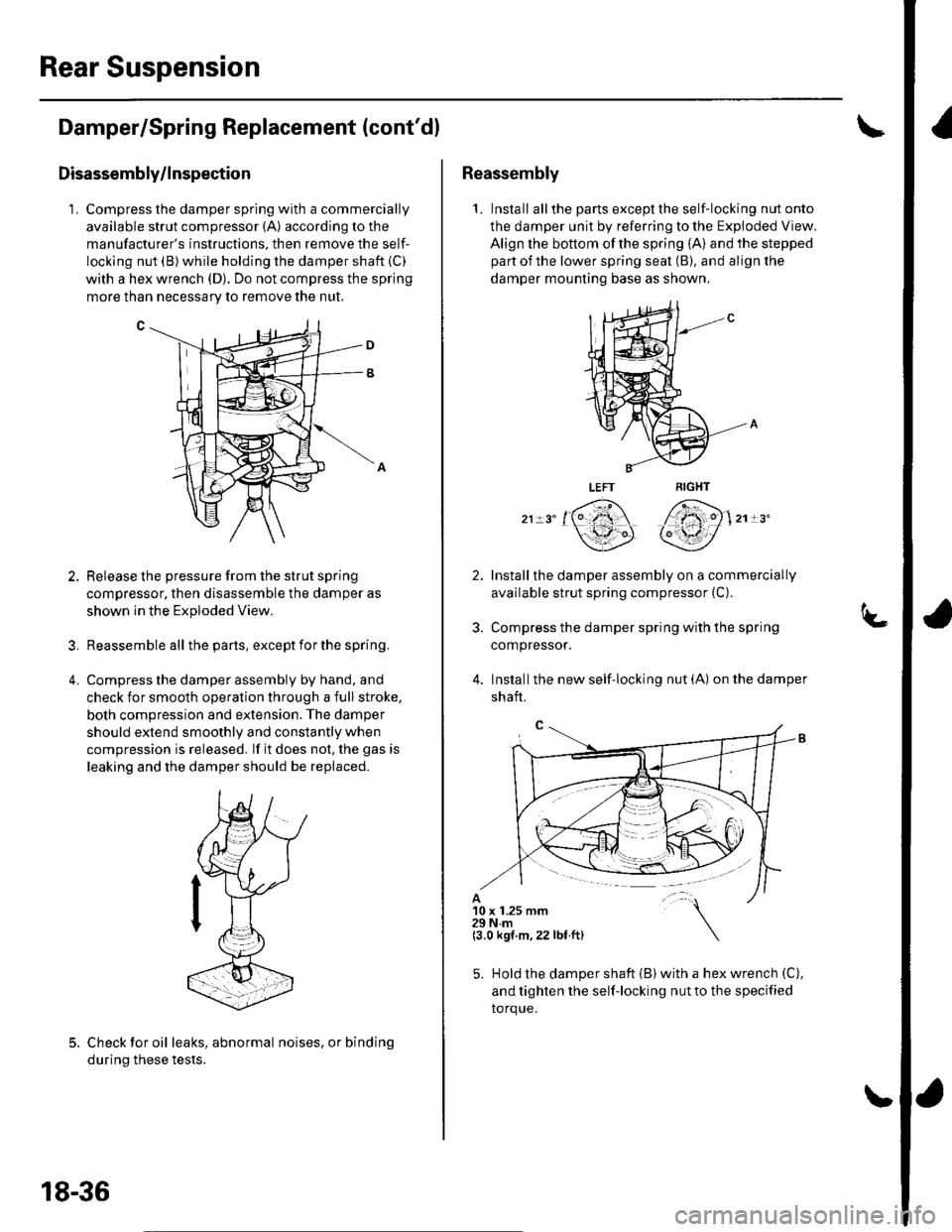
Disassembly/lnspection
1. Compress the damper spring with a commercially
available strut compressor (A) according to the
manufacturer's instructions. then remove the self-
locking nut (B)while holding the damper shaft (C)
with a hex wrench (D). Do not compress the spring
more than necessarv to remove the nut.
Release the pressure from the strut spring
compressor, then disassemble the damper as
shown ln the Exploded View.
Reassemble all the pans, except for the spring.
Compress the damper assembly by hand, and
check for smooth operation through a full stroke,
both compression and extension. The damper
should extend smoothly and constantly when
compression is released. lf it does not, the gas is
leaking and the damper should be replaced.
?
4.
Check for oil leaks, abnormal noises, or binding
during these tests.
18-36
Reassembly
1. Install allthe partsexceptthe self-locking nutonto
the damper unit by referring to the Exploded View.
Align the bottom of the spring {A} and the stepped
part of the lower spring seat (B), and align the
damper mounting base as shown,
,, '161 7fi)1,, "
\3P qY/
Installthe damper assembly on a commercially
available strut spring compressor (C).
Compress the damper spring with the spring
compressor.
Installthe new self'locking nut (A) on the damper
shaft.
10 x 1.25 mm29Nm(3.0 kgt m,22 lbt.ft)
5. Hold the damper shaft {B) with a hex wrench (C),
and tighten the self-locking nut to the specified
torque.
Page 613 of 1139
Gonventional Brake Components
IBrake Booster Test
Functional Test
1. With the engine stopped, press the brake pedal
several times to deplete the vacuum reservoir, thenpress the pedal hard, and hold itfor 15 seconds. lfthe pedal sinks, either the master cylinder is
bypassing internally, or the brake system (master
cylinder, lines. modulator, or calipers) is leaking.
2. Start the engine with the brake pedal pressed. lf thepedal sinks slightly, the vacuum booster is workingproperly. lf the pedal height does not vary, thebooster or check valve is faulty.
3. With the engine running, press the brake pedal
lightly. lfthe brake pedal sinks more than 1O mm
{3/8 in, ) in 3 minutes, the master cylinder is faulty.A slight change in pedal height when the Ay'C
compressor cycles on and off is normal. (The A,/C
compressor load changes the vacuum available tothe booster.)
Leak Test
1. Press the brake pedal with the engine running, thenstop the engine. lf the pedal height does not vary
while pressed for 30 seconds, the vacuum boosteris OK. lf the pedal rises, the booster is faulty.
2. With the engine stopped, press the brake pedal
several times using normal pressure. When thepedal is first pressed, it should oe row.
On consecutive applications, the pedal height
should gradually rise. lfthe pedal position does notvarv, check the booster check valve.
19-18
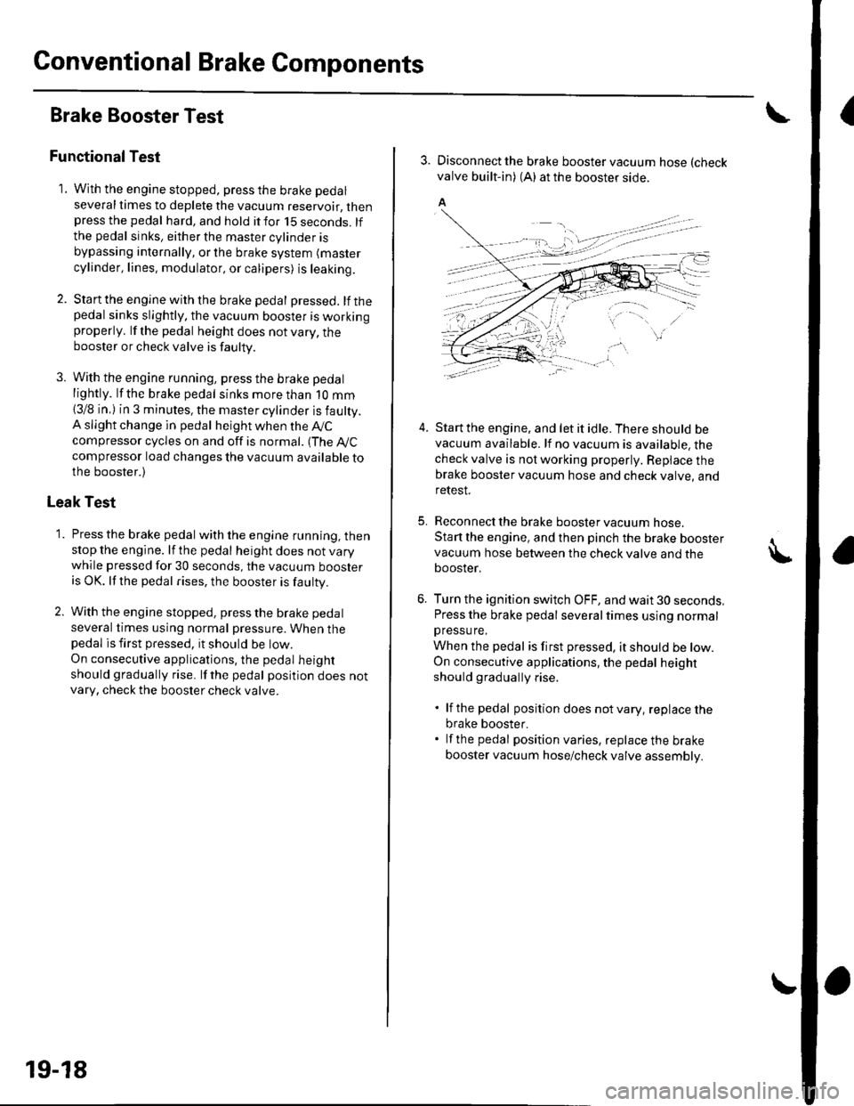
3. Disconnect the brake booster vacuum hose (check
valve built-in) (A) at the booster side.
5.
4.Start the engine, and let it idle. There should bevacuum available. lf no vacuum is available, thecheck valve is not working properly. Repiace thebrake booster vacuum hose and check valve, andrelesI.
Reconnect the brake booster vacuum nose.
Start the engine, and then pinch the brake boostervacuum hose between the check valve and thebooster,
Turn the ignition switch OFF, and wait 30 seconds,Press the brake pedal several times using normalpressu re,
When the pedal is first pressed, it should be low.On consecutive applications, the pedal height
should gradually rise.
. lf the pedal position does notvary, replacethe
brake booster.. lf the pedal position varies, replace the brake
booster vacuum hose/check valve assembly.
Page 773 of 1139
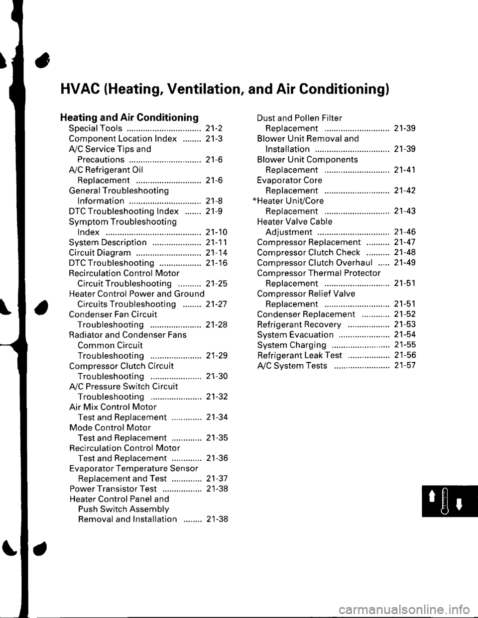
21-2
z t-'5
z t-o
z t-o
21-8
21-9
21-10
21-11
21-14
z t- to
HVAC (Heating, Ventilation, and Air Gonditioningl
Heating and Air Conditioning
SpecialTools
Comoonent Location lndex ........
A/C Service Tios and
Precautions
A,/C Refrigerant Oil
ReDlacement
General Troubleshooting
lnformation
DTC Troubleshooting Index .......
Symptom Troubleshooting
1ndex..............
System Description .....................
Circuit Diagram
DTC Troubleshooting ..................
Recirculation Control Motor
CircuitTroubleshooting .......... 21-25
Heater Control Power and Ground
Circuits Troubleshooting ........ 21-27
Condenser Fan Circuit
Troubleshooting ...................... 21-28
Radiator and Condenser Fans
Common Circuit
Troubfeshooting ...................... 21-29
Compressor Clutch Circuit
Troubleshooting ...................... 21-30
A,/C Pressure Switch Circuit
Troubleshooting ...................... 21-32
Air Mix Control Motor
Test and Reolacement ............. 21-34
Mode Control Motor
Test and Replacement ............. 21-35
Recirculation Control Motor
Test and Reolacement ............. 21-36
Evaporator Temperature Sensor
Reolacement and Test ............. 21-31
Power Transistor Test ................. 21 -38
Heater Control Panel and
Push Switch Assemblv
Removal and Installation ........ 21-38
Dust and Pollen Filter
Reolacement ..21-39
Blower Unit Removal and
lnstallation ...... 21-39
Blower Unit Comoonents
ReDlacement ............................ 21-41
Evaporator Core
Reolacement ..21-42*Heater Unit/Core
ReDlacement ..21-43
Heater Valve Cable
Adjustment .....21-46
CompressorReplacement .......... 21-47
Comoressor Clutch Check .......... 21-48
Comoressor Clutch Overhaul ..... 21-49
Compressor Thermal Protector
Reo1acement ............................ 21-51
Comoressor Relief Valve
Reolacement ............................ 21-51
Condenser Reolacement ............ 21-52
Refrigerant Recovery .................. 21-53
System Evacuation ...................... 21-54
System CharginS ......................... 21-55
Refrigerant LeakTest .................. 21-56
A,/C Svstem Tests ........................ 21-57