Compressor HONDA CIVIC 2003 7.G Owner's Guide
[x] Cancel search | Manufacturer: HONDA, Model Year: 2003, Model line: CIVIC, Model: HONDA CIVIC 2003 7.GPages: 1139, PDF Size: 28.19 MB
Page 819 of 1139
Heating and Air Gonditioning
1.
Compressor Clutch Check
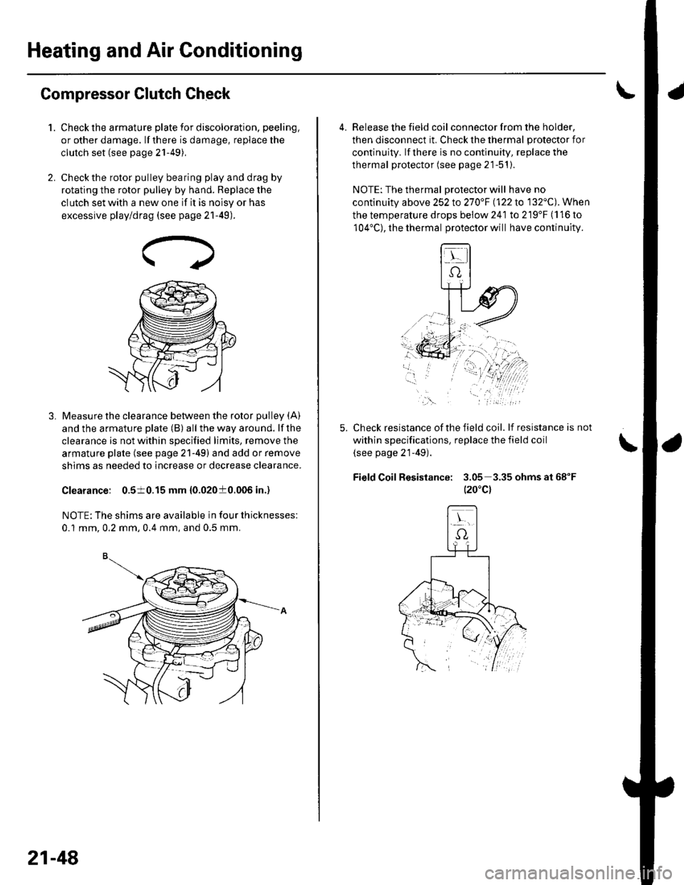
Check the armature plate for discoloration, peeling,
or other damage. lf there is damage, replace the
clutch set (see page 21-49),
Check the rotor pulley bearing play and drag by
rotating the rotor pulley by hand. Beplace the
clutch set with a new one if it is noisy or has
excessive play/drag (see page 21-49).
Measure the clearance between the rotor pulley (A)
and the armature plate (B) all the way around. lf the
clearance is not within specified limits, remove the
armature plate (see page 21-49) and add or remove
shims as needed to increase or decrease clearance.
Clearance: 0.510.15 mm {0.02010.006 in.)
NOTE: The shims are available in four thicknesses:
0.1 mm.0.2 mm,0.4 mm, and 0.5 mm.
21-48
a
4. Release the field coil con nector f rom the holder,
then disconnect it. Check the thermal protector for
continuity. lf there is no continuity, replace the
thermal protector (see page 21-51).
NOTE: The thermal Drotector will have no
continuity above 252to270"F \122lo 132'C). When
the temperature drops below 241 to 219'F (116 to
104'C), the thermal protector will have continuity.
Check resistance of the field coil. lf resistance is not
within specifications, replace the field coil
(see page 21-49).
Field Coil Resistance: 3.05 3.35ohmsat68"F
t20"c)
,\.
Page 820 of 1139
Compressor Clutch Overhaul
Special Tool Required
A,/C clutch holder, Robinair 10204. Kent-Moore J37872,
or Honda Tool and Equipment KMT-J33939,
commercially available
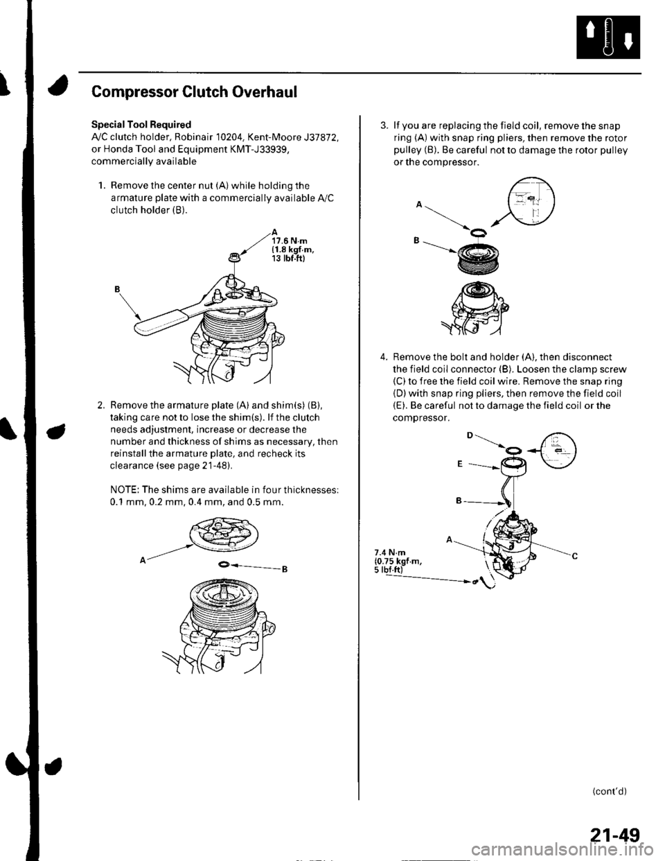
1. Remove the center nut (A) while holding the
armature plate with a commercially available A,/C
clutch holder (B).
17.6 N.m{1.8 kgf.m,13 tbt.ft)
Remove the armature plate (A) and shim(s) (B),
taking care not to lose the shim(s). lf the clutch
needs adjustment, increase or decrease the
number and thickness of shims as necessary, then
reinstallthe armature Dlate, and recheck its
clearance (see page 21-481.
NOTE: The shims are available in four thicknesses:
0.1 mm,0.2 mm,0.4 mm, and 0.5 mm.
9-=-g
3. lf you are replacing the field coil, remove the snap
ring (A) with snap ring pliers, then remove the rotor
pulley (B). Be careful not to damage the rotor pulley
or tne compressor.
4. Remove the bolt and holder (A). then disconnect
the field coil connector (B). Loosen the clamp screw(C) to iree the field coil wire. Remove the snap ring
{D)with snap ring pliers, then remove the field coil(E). Be careful not to damage the field coil or the
comoressor.
\ot
-@
/@h"
.ffi
7.4 N.m(0.75 kgf m,5 tbf.ft)---------------- ")
(cont'd)
21-49
Page 821 of 1139
Heating and Air Gonditioning
Compressor Clutch Overhaul (cont'd)
5. Reassemble the clutch in the reverse order of
disassembly, and note these items:
. Installthe field coil with the wire side facing
down, and align the boss on the field coil with the
hole in the compressor.. Clean the rotor pulley and compressor sliding
surfaces with contact cleaner or other
non-petroleum solvent..Install new snap rings, note the installation
direction, and make sure they are fully seated in
the groove.
. Make sure that the rotor pulley turns smoothly
after it's reassembled,. Route and clamp the wires properly or they can
be damaged by the rotor pulley.
21-50
Page 822 of 1139
Compressor Thermal Protector
Replacement
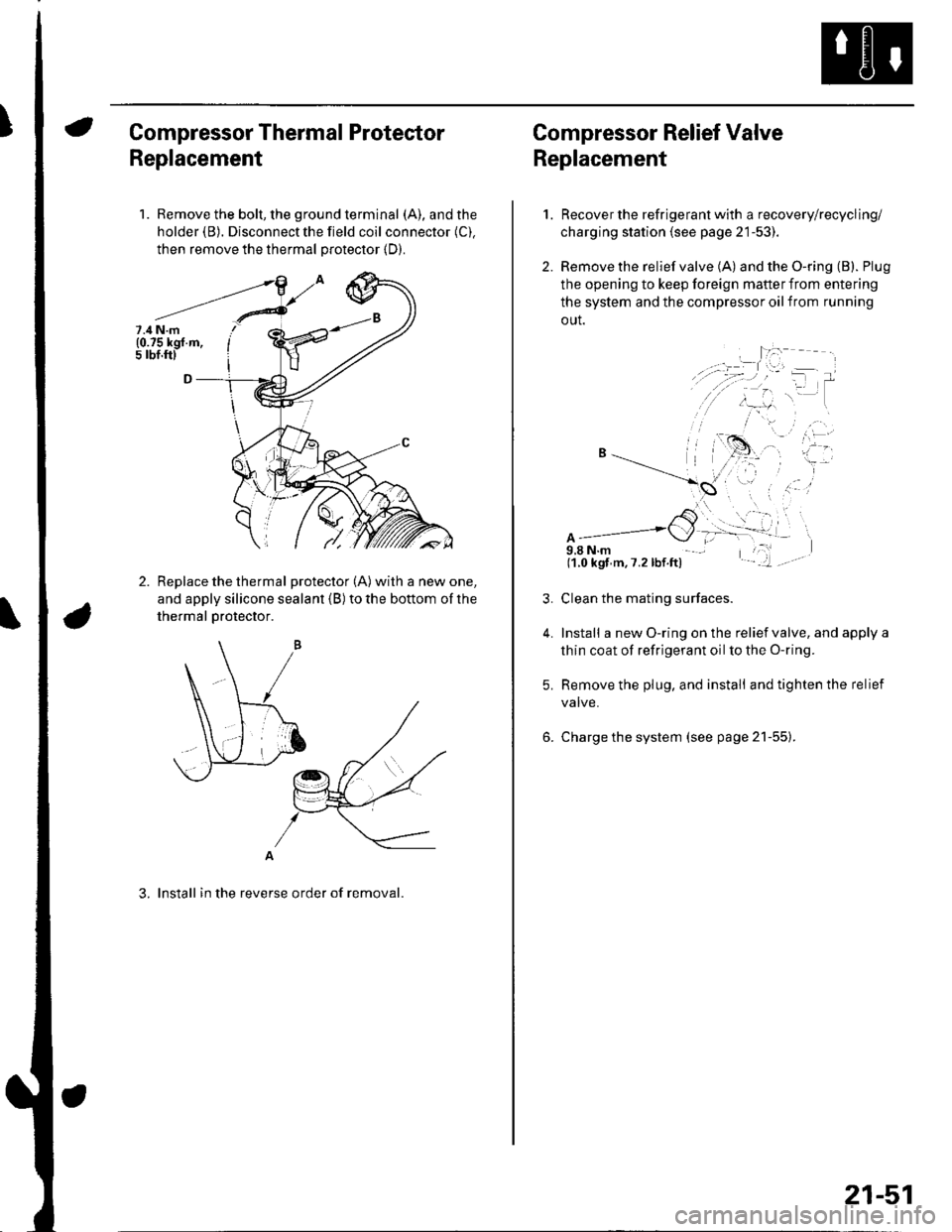
1. Remove the bolt, the ground terminal (A), and the
holder (B). Disconnect the field coil connector (C).
then remove the thermal protector (D).
Replace the thermal protector (A) with a new one,
and apply silicone sealant (B) to the bottom of the
thermal Drotector.
A
3. lnstall in the reverse order of removal.
7.4 N.m(0.75 kgf.m,5 rbf.ftl
Compressor Relief Valve
Replacement
2.
1.
4.
Recover the refrigerant with a recovery/recycling/
charging station (see page 21-53).
Remove the relief valve (A) and the O-ring (B). Plug
the opening to keep foreign mafter from entering
the system and the compressor oil from running
out.
A9,8 N.m(1.0 kgf m,7.2lbf.ft)
Clean the mating surfaces.
Install a new O-ring on the relief valve, and apply a
thin coat of refrigerant oil to the O-ring.
Remove the plug, and install and tighten the relief
valve.
Charge the system (see page 21-55).
21-51
Page 826 of 1139
System Charging
Air conditioning refrigerant or lubricant vapor
can irritate your eyes, nose, or throat.
Be carefulwhen connecting service equipment.
Do not breathe refrigerant or vapor,
Use only service equipment that is U.L.'listed and is
certified to meet the requirements of SAE J2210 to
remove HFC-134a {R-134a) from the air conditioning
system.
lf accidental system discharge occurs, ventilate the
work area before resuming service
Additional health and safety information may be
obtained from the refrigerant and lubricant
manufacturers.
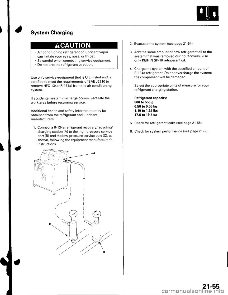
1. Connect a R-134a refrigerant recovery/recycling/
charging station (A) to the high-pressure service
pon (B) and the low-pressure service port {C), as
shown, following the equipment manufacturer's
instructions.
2.
3.
4.
Evacuate the system (see page 21'54).
Add the same amount of new refrigerant oil to the
system that was removed during recovery. Use
only KEIHIN SP-10 refrigerant oil.
Charge the system with the specified amount of
R-134a refrigerant. Do not overcharge the system;
the compressor will be damaged.
Select the appropriate units of measure for your
refrigerant charging station.
Refrigerant capacity:
500 to 550 g
0.50 to 0.55 kg
1.10 to 1.21 lbs
17.6 to 19.4 oz
Check for refrigerant leaks (see page 21'56).
Check for system performance (see page 21-58).
21-55
Page 828 of 1139
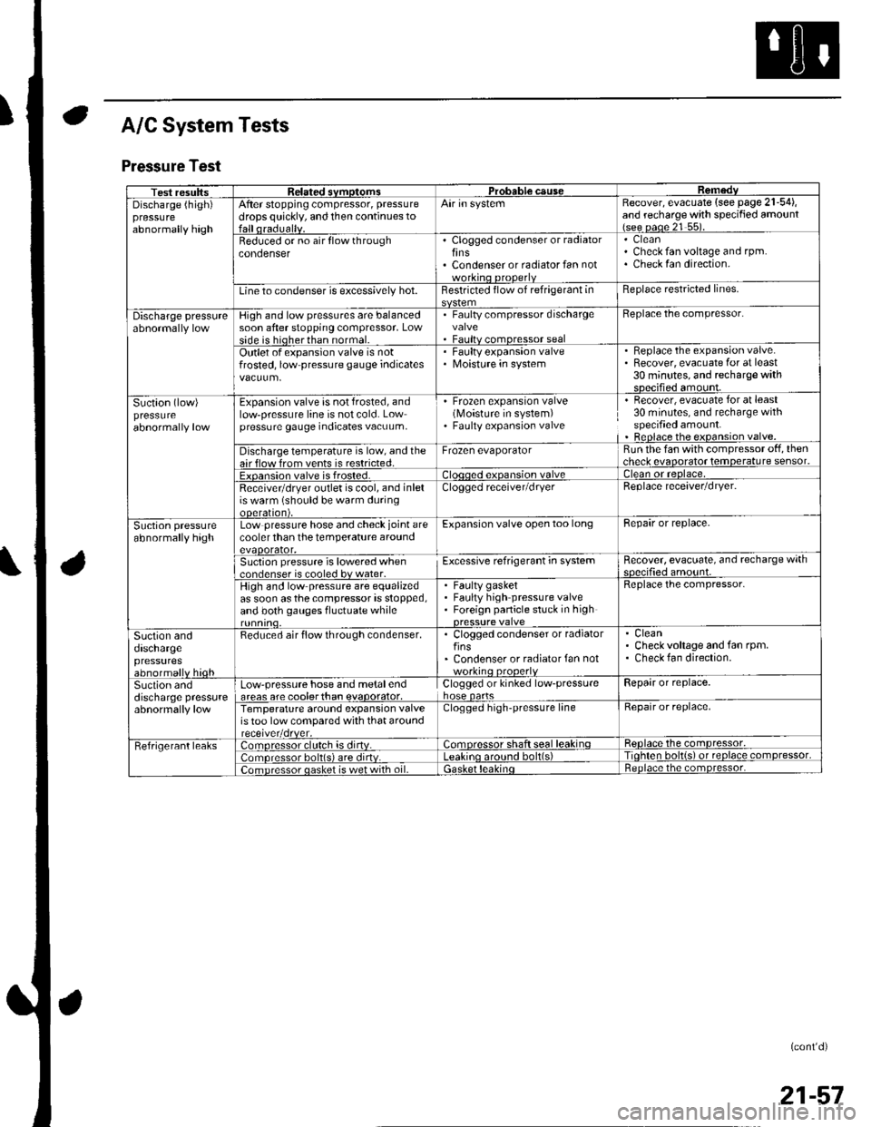
A/C System Tests
Pressure Test
Test resultssvmotom3DGaUSeDischarge (high)pressureabnormally high
After stopping compressor, pressure
drops quickly, and then continues toAir in systemRecover, evacuate (see page 21-54),and recharge with specified amount{see oaoe 21 55).
Beduced or no air flow throughcondenserClogged condenser or radiatorfinsCondenser or radiator fan not
CleanCheck fan voltage and rpm.Check fan direction.
Line to condenser is excessively hot.Restricted flow of refrigerant inReplace restricted lines.
Discharge pressureHigh and low pressures are balancedsoon after stopping compressor, Lowside is hioherthan normal.
. Faulty compressor dischargevalve. Faultv comoressor seal
Beplace the compressor.
Outlet of expansion valve is notfrosted, low pressure gauge indicatesFaulty expansion valveMoisture in system
. Replace the expansion valve.. Recover, evacuate for at least30 minutes, and recharge withsDecified amount.
Suction (low)pressureabnormally low
Expansion valve is not frosted, andlow-pressure line is not cold. Lowpressure gauge indicates vacuum,
' Frozen expansion valve(Moisture in system). Faulty expansion valve
Recover, evacuate for at least30 minutes, and recharge withspecified amount.Beplace the expansion valve.
Discharge temperature is low, and theair flow from vents is restricted.Frozen evaporatorRun the fan with compressor off, thencheck evaooratot temoerature sensor.
Exoansion valve is frosted.ean or reolace,
Receivetdryer outlet is cool, and inletis warm (should be warm duringooeralton),
Clogged receiver/dryerReplace receaver/dryer.
Suction pressureabnormally highLow pressure hose and check joint arecooler than the temperature aroundevaoorator,
Expansion valve open too longBepair or replace.
Suction pressure is lowered when..nrlenser is cooled bv water.Excessive refrigerant in systemRecover, evacuate, and recharge withqnp.ifie.lamo'rnr
High and low pressure are equalizedas soon asthecompressor is stopped,and both gauges fluctuate while
Faulty gasketFaulty high pressure valveForeign panicle stuck in high
Replace the compressor.
Suction anddaschargepressuresabnormallv hioh
Reduced air flow through condenser.. Clogged condenser or radiatorfins' Condenser or radiator fan notworkino orooerlv
CleanCheck voltage and fan rpm.Check fan direction.
Suction anddischarge pressureabnormally low
Low-pressure hose and metalendareas are coolerthan evaoorator,Clogged or kinked low-pressurehose oartsRepair or replace.
Temperature around expansion valveis too low compared with that aroundClogged high-pressure lineRepair or replace,
Fefrigerant leaks:omoressor clulch is dirtv.:omoressor shaft seal leakinqReolace the comDressor,
lomoressor bolt(s) are dirtv.no around bolt(s)Tiohten bolt{s) ot reolace comDressor,
;omDressor oasket is wet with oil.ietnoace the comoressor.
(cont'd)
21-57
Page 875 of 1139
Fuse/Relay Boxes
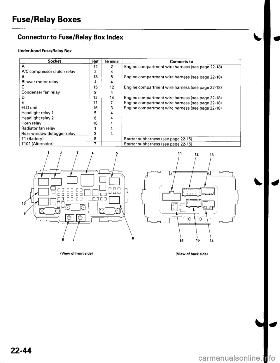
Connector to Fuse/Relay Box Index
Under-hood Fuse/Relay Box
lview of tront sidel
- a-------) | | T---r .-:-tt || tL__.1 | I
------tttL""tt tt ttL lL ltl'".-
{View of back side)
SocketRefTerminalConnects to
Ay'C compressor clutch relay
B
Blower motor relay
c
Condenser fan relay
D
E
ELD unit
Headlight relay 1
Headlight relay 2
Horn relay
Radiator fan relay
Rear window defoqqer relay
14
2
15
91'
11
to
5
6
10'l
J
2
4
5
4
4
14
7
3
4
4
4
4
Engine compartment wire harness (see page 22-18)
Engine compartment wire harness (see page 22-18)
Engine compartment wire harness (see page 22-18)
Engine compartment wire harness (see page 22-18)
Engine compartment wire harness (see page 22-18)
Engine compartment wire harness {see page 22-18)
T1 (Batterv)8Starter subharness (see oaqe 22-15)
T101 (Alternator)7Starter subharness {see oaoe 22-'15}
""""-l- tr -l T _l T Il
I tTt Tr,/^-------lFrr^l -/1-l sz- l:!)L' lrt
22-44
Page 877 of 1139
Power Distribution
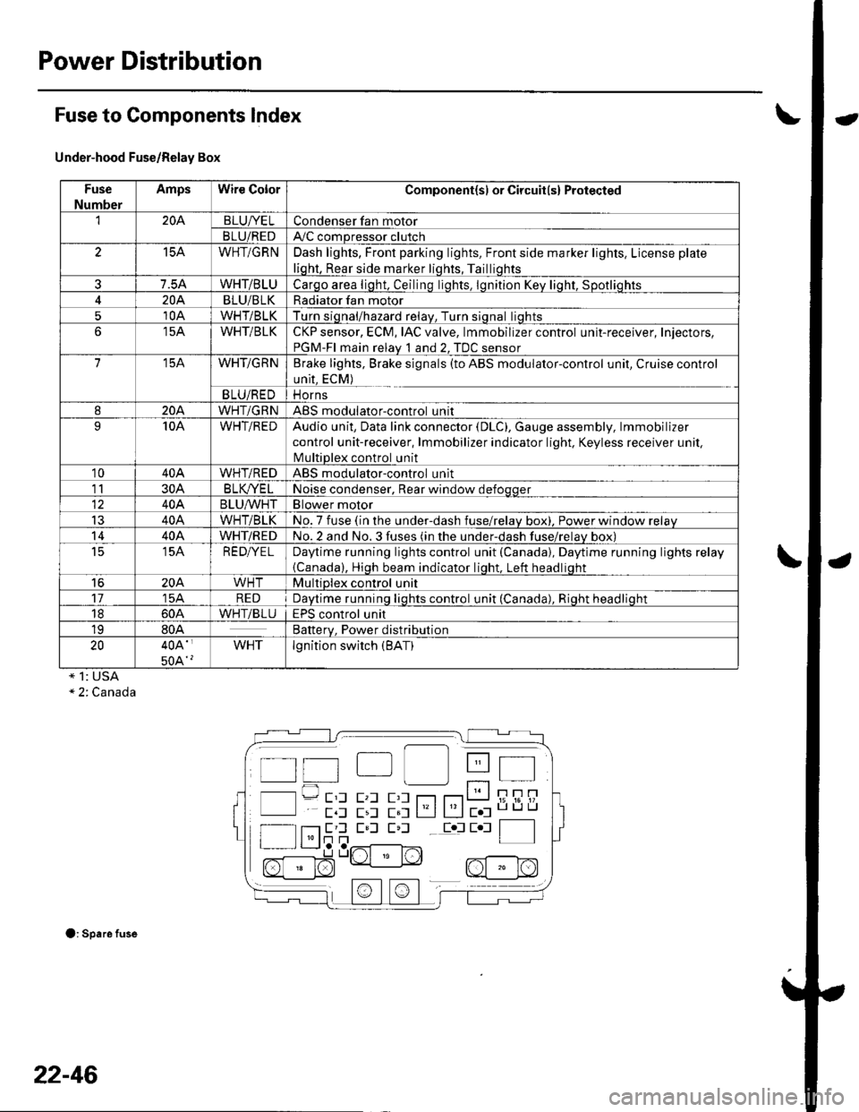
Fuse to Components lndex
Under-hood Fuse/Relay Box
Fuse
Number
AmpsWire ColorComponent(sl or Circuit(s) Protected
'I204BLUI/ELCondenser fan motor
BLU/REDAy'C compressor clutch
15AWHT/GRNDash lights, Front parking lights, Front side marker lights, License plate
liqht, Rear side marker liqhts, Tailliqhts
7.5AWHT/BLUCarqo area liqht, Ceilinq liqhts. lqnition Kev liqht. Sootliohts
204BLU/BLKRadiator fan motor
510AWHT/BLKTurn siqnal/hazard relav, Turn siqnal liqhts
15AWHT/BLKCKP sensor, ECM, IAC valve, lmmobilizer control unit-receiver, Injectors,
PGM-FI main relav 1 and 2. TDC sensor
715AWHT/GRNBrake lights, Brake signals (to ABS modulator-control unit, Cruise control
unit, ECM)
BLU/REDi1 Orns
820AWHT/GRNABS modulatorcontrol unit
910AWHT/REDAudio unit, Data link connector (DLC), Gauge assembly, lmmobilizer
control unit-receiver, lmmobilizer indicator light. Keyless receiver unil,
lvlultiDlex control unit
1040AWHT/REDABS modulator-control unit
1130AB LK/YE LNoise condenser, Rear window defoqqer
40ABLU^^/HTBlower motor
IJ40AWHT/BLKNo. 7 fuse (in the under-dash fuse/relav box), Power window relav
1440AWHT/REDNo.2 and No.3 fuses (in the under-dash fuse/relav box)
t515AREDI/ELDaytime running lights control unit (Canada), Daytime running lights relay
{Canada), Hioh beam indicator liqht. Left headliqht
16204WHTMultiplex control unit
1715AREDDavtime runninq liqhts control unit (Canada). Rioht headlioht
1860AWHTiBLUEPS control unit
1980ABatterv. Power distribution
2040A'
50A'?
WHTlgnition switch (BAT)
* 1: USA" 2. Canada
O: Spare fuse
t t"| lll Itt 4t I
l l---- E'l E,l E,l r--r r---r t__J i; i6'!/'
E,l E,l E,l Eol E l f__--lI l'lr]n | |I r L__J,a ,..r^{-------l^-,
n[:]$"Lrt " N2, nf - r^l
22-46
Page 878 of 1139
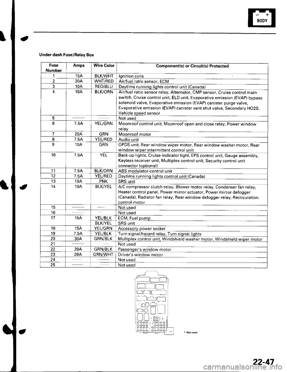
Under-dash Fuse/Relay Box
Fuse
Number
AmpsWire ColorComponent(s) or Circuit(s) Protected
115ABLKA/VHTlgnition coils
2204WHT/REDAirlfuel ratio sensor, ECM
310ARED/BLUDaytime running Iights control unit {Canada)10ABLI(ORNAir/fuel ratio sensor relay, Alternator, CMP sensor, Cruise control main
switch, Cruise control unit. ELD unit, Evaporative emission (EVAP) bypass
solenoid valve, Evaporative emission (EVAP)canister purge valve,
Evaporative emission (EVAP) canister vent shut valve, Secondary H02S,
Vehicle speed sensor
5Not used
67.5AYEUGRNMoonroof control unit, Moonroof open and close relay, Power window
relaV
7204GRNMoonroof motor
I7.5AYEUREDAudio unit
910AGRNOPDS unit, Rear window wiper motor, Rear window washer motor, Rear
window wiper intermittent control unit
107.54YELBack-up lights, Cruise indicator light, EPS control unit, Gauge assembly,
Keyless receiver unit, Multiplex control unit, Security control unit
connector (optional)
117.5ABLIVORNABS modulator-control unit
127.5AYEUREDDaytime runnino liohts control unit (Canada)
1310APNKSRS unit't410ABLK/YE LA,,/C compressor clutch relay, Blower motor relay, Condenser fan relay,
Heater control panel, Power mirror actuator, Power mirror defogger(Canada), Radiator fan relay, Rear window defogger relay, Recirculation
control motor1ENot used
loNot used
1715AYE L/B LKECM, Fuel pump
B LK/YE L>H> Unrr
1815AYEUGRNAccessory power socket
197.5AYEUBLKTurn siqnal/hazard relav, Turn siqnal liohts
2030AGRN/BLKMultiplex control unit, Windshield washer motor. Windshield wioer motor21Not used
22204GRN/BLKPassenqer's window motor
2320A.G R N,A/VHTDriver's window motor
24Not used
25Not used
__^:Hr tl_l
f at-t
at I
r^,rl fl
!!;r -
!339,i;s!!sf Fnf : |rnITf
22-47
Page 1002 of 1139
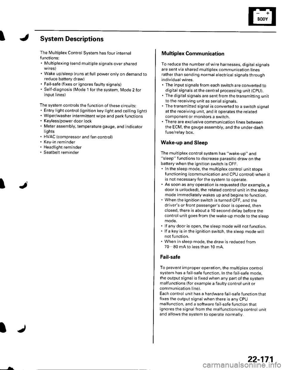
ISystem Descriptions
The Multiplex Control System has four internal
functions:. Multiplexing (send multiple signals over sharedwtres). Wake up/sleep (runs at full power only on demand toreduce battery draw). Fail-safe (fixes or ignores faulty signals). Self-diagnosis (Mode 1 for the system, Mode 2 for
input lines)
The system controls the function of these circuits:. Entry lightcontrol (ignition key lightandceiting light). Wiper/washer intermittent wipe and park functions. Keyless/power door lock. Meter assembly, temperature gauge, and indicator
lights. HVAC (compressor and fan control). Key-in reminder. Headlight reminder. Seatbelt reminder
JI
/ar
22-171
Multiplex Communication
To reduce the number of wire harnesses, digital signals
are sent via shared multiplex communication linesrather than sending normal electrical signals throughindividual wires.. The input signals from each switch are converted todigital signals at the central processing unit (CpU).. The digital signalsaresentfromthetransmitting unitto the receiving unit as serial signals.. The transmitted signal is converted to a switch signalat the receiving unit, and it operates the related
component or monitors a swltch.. There are exclusive communicalion lines between
the ECM, the gauge assembly, and the under,dash
fuse/relay box.
Wake-up and Sleep
The multiplex control system has "wake-up" and"sleep" functions to decrease parasitic draw on the
battery when the ignition switch is OFF.. ln the sleep mode, the multiplex control unit stops
functioning (communication and CPU control) when it
is not necessary for the system to operate.. As soon as any operation is requested (for example, adoor is unlocked), the related control unit in the sleep
mode immediately wakes up and begins to function.. When the ignition switch is turned OFF, and the
driver's or front passenger's door is opened, then
closed, there is about a 10 second delay before the
control unit goes from the wake-up mode to the sleepmode.. lf any door is open, the sleep mode will not function.. lf a key is in the ignition switch, the sleep mode will
not function.. When in sleep mode, the draw is reduced from
70 80 mA to less than 10 mA.
Fail-safe
To prevent improper operation, the multiplex controlsystem has a fail-safe function. In the fail-safe mode,
the output signal js fixed when any part of the systemmalfunctions (for example a faulty control unit orcommunication line).
Each control unit has a hardware fail-safe function thatfixes the output signal when there is any CPUmalfunction, and a software fail-safe function thatignores the signal from the malfunctioning control unitand allows the system to operate normally.