EGR HONDA CIVIC 2003 7.G User Guide
[x] Cancel search | Manufacturer: HONDA, Model Year: 2003, Model line: CIVIC, Model: HONDA CIVIC 2003 7.GPages: 1139, PDF Size: 28.19 MB
Page 516 of 1139

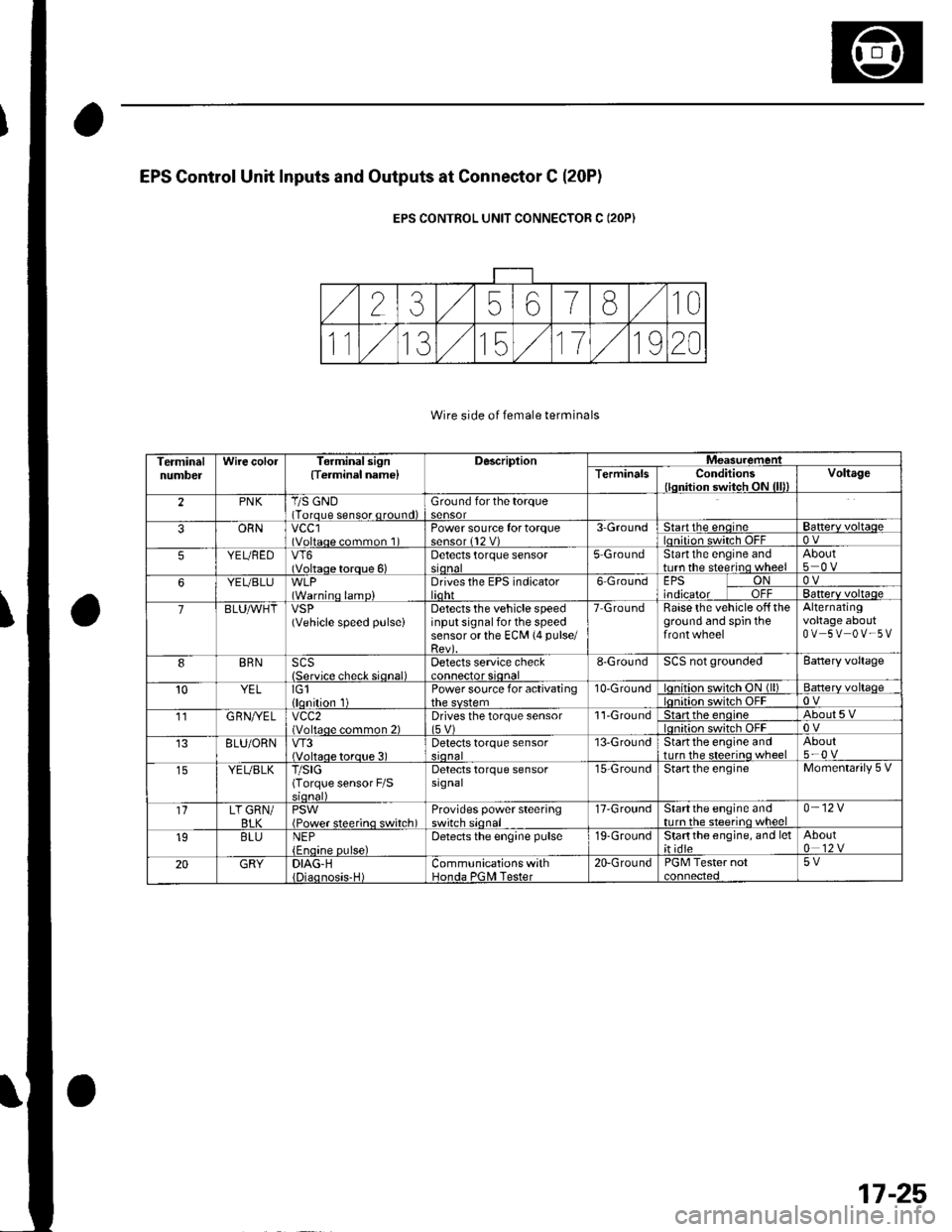
EPS Gontrol Unit Inputs and Outputs at Connestor C (20P1
EPS CONTROL UNIT CONNECTOR C (2OP)
Wire side of female terminals
TerminalnumbelWire colorTerminal sign{Terminel name}DescriplionMeasuremeniTerminalsConditions{lqnition switch ON {lll)Voltage
2PNKT/S GND(Torque sensor qround)Ground for the torque
ORNvccl(Voltaqe common 1Power source fortorque3-Groundtartthe enqrneBa$erv voltaqeOV
5YEUBEDVT6(Voltaqe torque 6)Detects torque sensorstonal5 GroundStartthe engine andturn the steerino wheelAbout
YEUBLU(Warninq lamp)Drives the EPS indicatorlidhr6 GroundEPS ONtnotcatol uTl-OVBanerv voltaqe
7BLUAVHTVSP(Vehicle speed pulseiDetects the vehicle speedinput signal for the speedsensor or the ECM (4 pulse/
Raise the vehicle off theground and spin theAlternatingvoltage aboutOV 5V OV-5V
BRNSCS{Servjco check siqnal)Detects service check8-GroundSCS not groundedBattery voltage
10YELIG1llqnition 1Power source for activating10-Groundon switch ON (ll)Batterv voltaqeon switch OFF11G RN//ELvcc2(Voltaqe common 2)Drives the torque sensor1'l-Groundtan the enoineAbout5Von switch OFF8LU/ORNVT3(Voltaoe toroue 3)Detects torque sensor13-GroundStartthe engine andtrrrn the steerino wheelAbout5-0 v
YEUBLKT/SIG(Torque sensor F/SDetects torque sensorsrgnal15-GroundStartthe engineMomentarily 5 V
1'lLT GRN/BI KPSWiPower steerino switch)Provides power steeringswitch sionall7-GroundStartthe engine andnrrn the steerino wheel0-12V
19BLUNEPDetects the engine pulse19-GroundStartthe engine, and let;t idte
20GRYDIAG-HCommunications withHonda PGNI Tester20-GroundPGM Tester not5V
17-25
Page 541 of 1139

EPS Components
(Motor RemovaUlnstallation (cont'dl
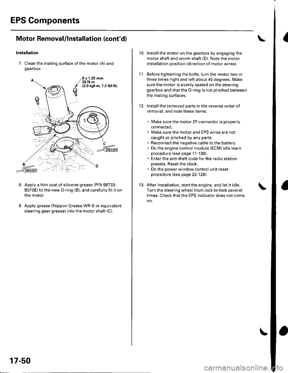
lnsiallation
7. Clean the mating surface of the motor (A) and
gearbox.
Apply a thin coat of silicone grease (P/N 08733-
8070E)to the new O-ring (B), and carefully fit it on
the motor.
Apply grease {Nippon Grease WR-S or equivalent
steering gear grease) into the motor shaft (C).
qE
8 x '1.25 mm20 N.m12.0 kgt.m,7 .2lbl ftl
L==-c].E@
9.
17-50
r0.Install the motor on the gearbox by engaging the
motor shaft and worm shaft (D). Note the motor
installation position {direction of motor wires).
Before tightening the bolts, turn the motor two or
three times right and left about 45 degrees. lvlake
sure the motor is evenly seated on the steering
gearbox and that the O-ring is not pinched betlveen
the mating surfaces.
Installthe removed Darts in the reverse order of
removal. and note these items:
lvlake sure the motor 2P connector is properly
connected.
lvlake sure the motor and EPS wires are not
caught or pinched by any parts.
Reconnect the negative cable to the battery.
Do the engine control module (ECM) idle learn
procedure (see page 11-139).
Enter the anti-theft code for the radio station
Dresets. Reset the clock,
Do the oower window control unit reset
procedure (see page 22-1241.
After installation, start the engine, and let it idle.
Turn the steering wheel from lock-to-lock several
times. Check that the EPS indicator does not come
on.
11.
12.
13.
Page 551 of 1139

EPS Components
{Steering Gearbox Overhaul (cont'dl
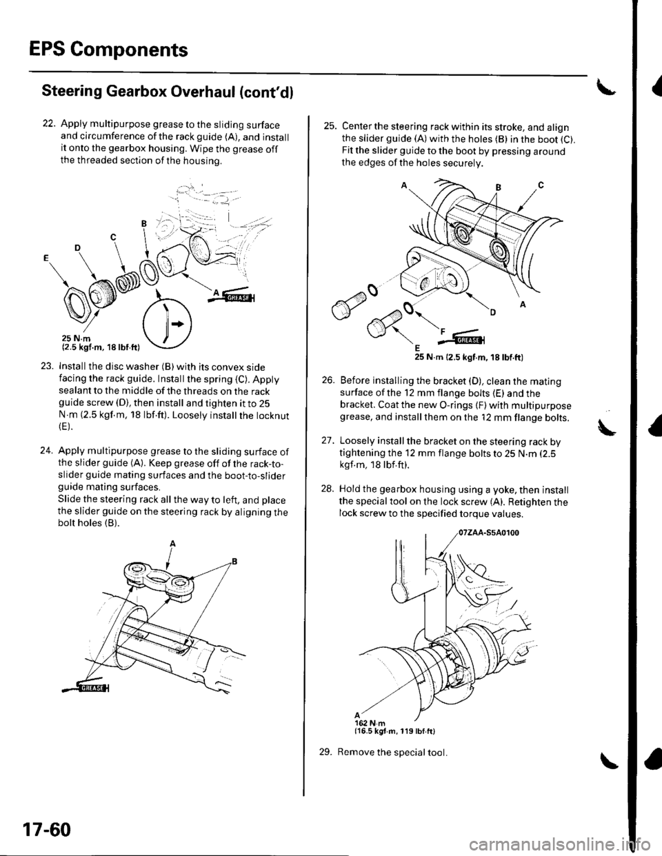
22. Apply multipurpose grease to the sliding surfaceand circumference ofthe rackguide (A), and installit onto the gearbox housing. Wipe the grease offthe threaded section ofthe housrno.
...'.
,. ,l
.j
23. Installthe disc washer (B)with its convex sidefacing the rack guide. Installthe spring (C). Appty
sealant to the middle of the threads on the rackguide screw (D), then install and tighten it to 25
N m (2.5 kgf.m, 18 lbf.ft). Loosely instatlrhe tocknut(E).
24. Apply multipurpose grease to the sliding surface ofthe slider guide (A). Keep grease off of the rack-to-slider guide mating surfaces and the boot-to-sliderguide mating surfaces.
Slide the steering rack all the way to left, and place
the slider guide on the steering rack by aligning thebolt holes (B).
'1 - .- =-1, -
17-60
29.
25. Centerthe steering rack within its stroke, and alignthe slider guide (A)with the hotes (B) in the boot (C).
Fit the slider guide to the boot by pressing around
the edges of the holes securely
E25 N.m 12.5 kgt.m, 18 tbt.ft)
26. Before installing the bracket (D), clean the mating
surface ofthe 12 mm flange bolts (E) and thebracket. Coat the new O-rings {F) with multipurposegrease, and installthem on the '12 mm flange bolts.
27. Loosely install the bracket on the steering rack bytightening the 12 mm flange bolts to 25 N.m (2.5
kgf.m, 18lbf.ft).
28. Hold the gearbox housing using a yoke, then install
the specialtool on the lock screw (A). Retighten thelock screw to the specified torque values.
{16.5 kgt.m, 119 lbf.ft}
Remove the special tool.
A
Page 835 of 1139

Body Electrical
General Troubleshooting Information (cont'd)
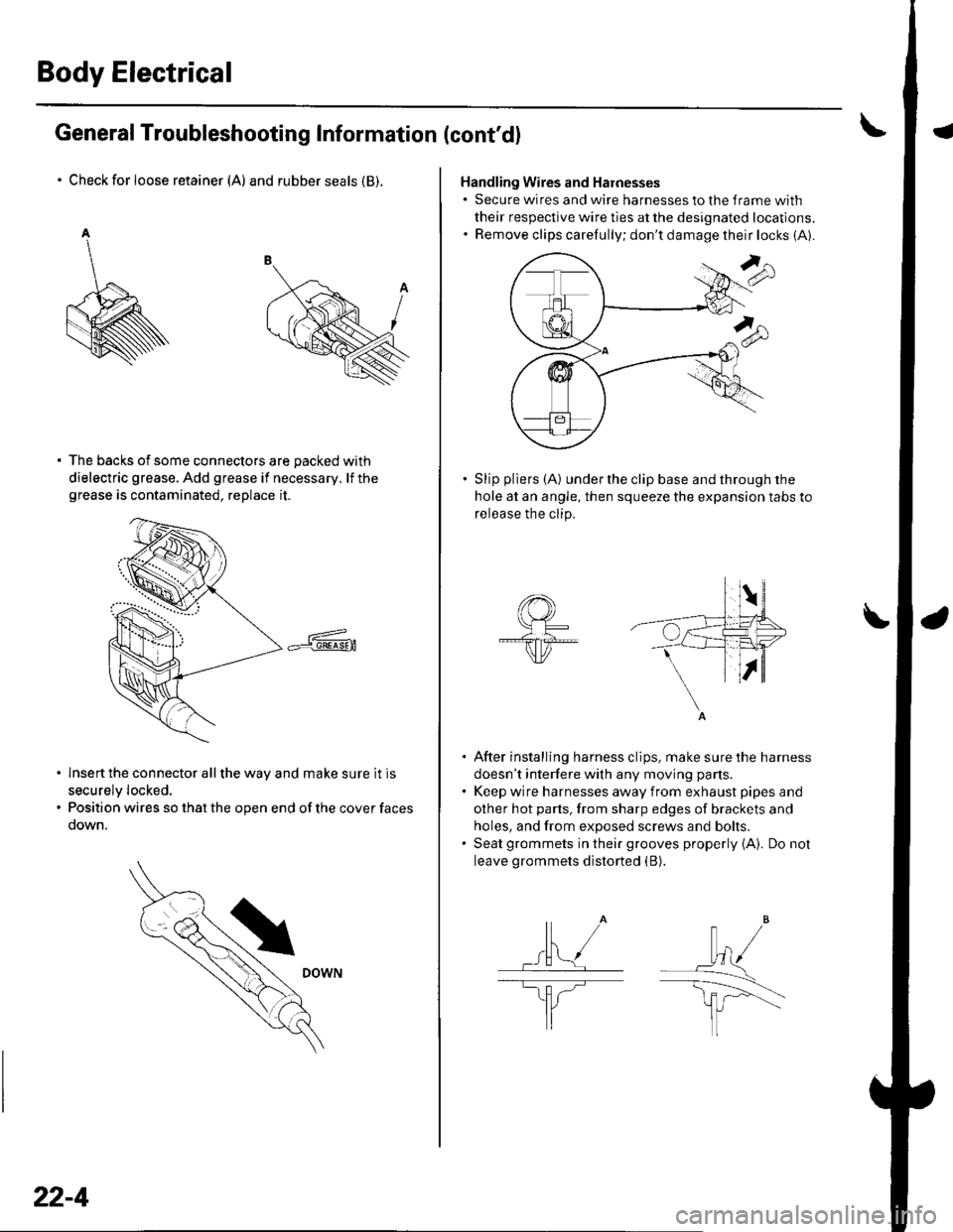
Check for loose retainer (A) and rubber seals (B).
The backs of some connectors are packed with
dielectric grease. Add grease if necessary. lf thegrease is contaminated, replace it.
lnsert the connector all the way and make sure it is
securelv locked.
Position wires so that the open end of the cover faces
oown.
22-4
Handling Wires and Harnesses. Secure wires and wire harnesses to lhe frame with
their respective wire ties at the designated locations.. Remove clips carefully; don't damage their locks (A).
Slip pliers (A) under the clip base and through the
hole at an angle, then squeeze the expansion tabs to
release the clip.
After installing harness clips, make sure the harness
doesn't interfere with any moving pans.
Keep wire harnesses away from exhaust pipes and
other hot parts, from sharp edges of brackets and
holes, and from exposed screws and bolts.
Seat grommets in their grooves properly {A). Do not
leave grommets distorted (B).
lt" /wl/
\--------\tfl r'---'..-
It
J
|,f . ./.ll t/
----E; F.�'l/
I