EGR HONDA CIVIC 2003 7.G Workshop Manual
[x] Cancel search | Manufacturer: HONDA, Model Year: 2003, Model line: CIVIC, Model: HONDA CIVIC 2003 7.GPages: 1139, PDF Size: 28.19 MB
Page 155 of 1139
Cylinder Honing
Only a scored or scratched cylinder bore should be
noneo.
Measure the cylinder bores {see page 7-15).
lf the block is to be reused, hone the cylinders and
remeasure the bores.
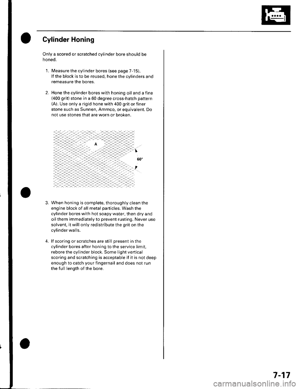
Hone the cylinder bores with honing oil and a fine(400 grit) stone in a 60 degree cross-hatch pattern
(A). Use only a rigid hone with 400 grit or finer
stone such as Sunnen, Ammco, or equivalent. Do
not use stones that are worn or broken.
When honing is complete, thoroughly clean the
engine block of all metal particles. Wash the
cylinder bores with hot soapy water, then dry and
oil them immediately to prevent rusting. Never use
solvent, it will only redistribute the grit on the
cylinder walls.
lf scoring or scratches are still present in the
cylinder bores after honing to the service limit,
rebore the cylinder block. Some light vertical
scoring and scratching is acceptable if it is not deep
enough to catch your fingernail and does not run
the full length of the bore.
'L
3.
7-17
Page 236 of 1139
wEc/wc
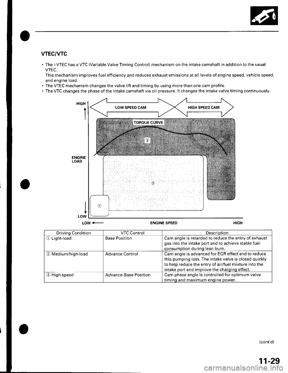
The i-WEC has a VTC (Variable Valve Timing Control) mechanism on the intake camshaft in addition to the usual
VTEC.
This mechanism improves fuel efficiency and reduces exhaust emissions at all Ievels of engine speed, vehicle speed.
and engine load.
The VTEC mechanism changes the valve lift and timing by using more than one cam profile.
The VTC changes the phase of the intake camshaft via oil pressure. lt changes the intake valve timing continuously.
HIGH
i
LOW <-ENGINE SPEED
Drivino ConditionVTC ControlDescriDtion
Qr Light-loadBase PositionCam angle is retarded to reduce the entry of exhaust
gas into the intake port and to achieve stable fuel
consumDtion durinq lean bu rn.
?l M ed iu m/h ig h-loadAdvance ControlCam angle is advanced for EGR effect and to reduce
this pumping loss. The intake valve is closed quickly
to help reduce the entry of airlfuel mixture into the
intake port and improve the charging effect.
€) High speedAdvance-Base PositionCam phase angle is controlled for optimum valve
timinq and maximum enoine oower.
{cont'd)
11-29
Page 237 of 1139
Fuel and Emissions Systems
(System Descriptions (cont'dl
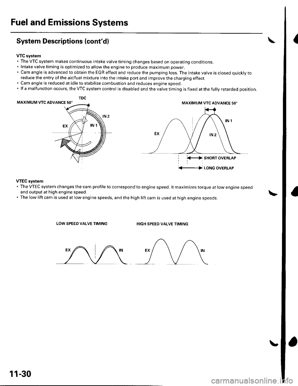
VTC system. The VTC system makes continuous intake valve timing changes based on operating conditions.. Intake valve timing is optimized to allow the engine to produce maximum power.'CamangleisadvancedtoobtaintheEGReffectandreducethepumpingloss.Theintakevalveisclosedquicklyto
reduce the entry of the airlfuel mixture into the intake port and improve the charging effect.. Cam angle is reduced at idle to stabilize combustion and reduces engine speed.'lfamalfunctionoccurs,theVTCsystemcontrol is disabled and the valve timing is fixed at the fully retarded position.
MAXIMUM VTC ADVANCE 50'
i l(-4 sHoRT oVERLAP
'+-|l LoNG oVERLAP
VTEC system' The VTEC system changes the cam profile to correspond to engine speed. lt maximizes torque at low engine speedand output at high engine speed.. The low lift cam is used at low engine speeds, and the high lift cam is used at high engine speeds.
LOW SPEED VALVE TIMINGHIGH SPEED VALVE TIMING
TDC
MAXIMUM VTC ADVANCE 50'
11-30
Page 382 of 1139
DTC Pl456: EVAP Control(Fuel Tank Svstem)
System Leakage
The fuel system is designed to allow specified
maximum vacuum and pressure conditions. Do not
deviate from the vacuum and pressure tests as
indicated in these procedures. Excessive pressure/
vacuum would damage the EVAP components or cause
eventual fuel tank failure.
Special Tools Required
Vacuum Pump/Gauge, 0-30 in. Hg A973X-041-XXXXX
This is a two-trip code. Once cleared, it cannot be
reproduced in one trip. Also, cenain specific driving
and ambient conditions must occur before the ECM will
complete the system checks. Additional test drives may
still not meet the specific conditions needed to
reproduce the code.
Follow these troubleshooting procedures carefully to
ensure the integrity of the system and to confirm the
cause of the problem or code.
NOTE: Fresh fuel has a higher volatility that createsgreater pressure/vacuum. The optimum condltlon for
testing is fresh fuel, and must be less than a full tank. lf
possible, to assist in leak detection, add 1 gallon of
fresh fuel to the tank (as long as it will not fill the tank).just before starting these procedures.
Fuel Fill Cap Check
1. Check the fuel fill cap (the cap must say "lf not
tightened 3 clicks check engine light may come
on" ).
ls the proper luel till cap installed and properly
tightened?
YES Go to step 2.
NO- Replace or tighten the cap.I
2. Check the fuel fill cap seal.
ls the tuel fill cap seal missing or damaged?
YES- Replace the fuel fill cap.I
NO The fuelfill cap is OK. Go to step 3.
EVAP Canister Purge Valve Test
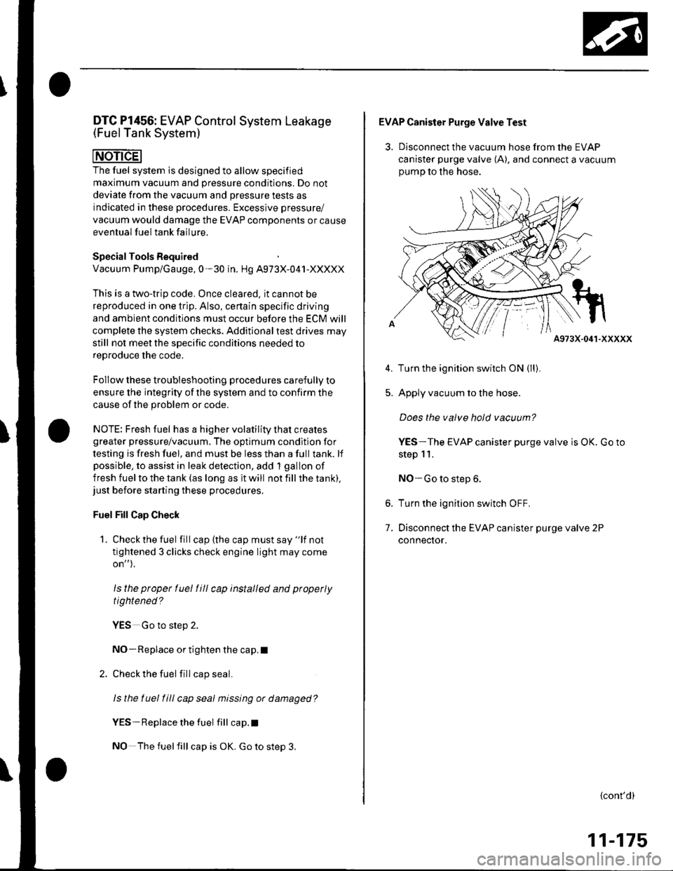
3. Disconnect the vacuum hose from the EVAP
canister purge valve (A), and connect a vacuum
oumo to the hose.
A973X-041-XXXXX
Turn the ignition switch ON (ll).
Apply vacuum to the hose.
Does the valve hold vacuum?
YES-The EVAP canister purge valve is OK. Go to
step 11.
NO-Go to step 6.
Turn the ignition switch OFF.
Disconnect the EVAP canister purge valve 2P
connecror.
5.
7.
{cont'd)
11-175
Page 387 of 1139
EVAP System
DTC Troubleshooting (cont'd)
DTC Pl457: EVAP Control System(EVAP Canister System)
Leakage
The fuel system is designed to allow specified
maximum vacuum and pressure conditions. Do not
deviate from the vacuum and pressure tests as
indicated in these procedures. Excessive pressure/
vacuum would damage the EVAP components or
cause eventual fuel tank system failure.
SpecialTools Required
Vacuum pump/gauge, 0-30 in.Hg A973X-041-XXXXX
This is a two-trip code. Once cleared, it cannot be
reproduced in one trip. Also, certain specific driving
and ambient conditions must occur before the ECfM will
complete the system checks, Additional test drives may
still not meet the specific conditions needed to16^r^.1' '^6 rh6 ^^.16
Follow these troubleshooting procedures carefully to
ensure the integrity of the system and to confirm the
cause of the problem or code.
NOTE: Fresh fuel has a higher volatility lhat creates
greater pressure/vacuum. The optimum condition for
testing is fresh fuel, and there must be less than a full
tank. lf possible, to assist in leak detection, add I gallon
of fresh fuel to the tank (as long as it will not fill the
tank), just before starting these procedures.
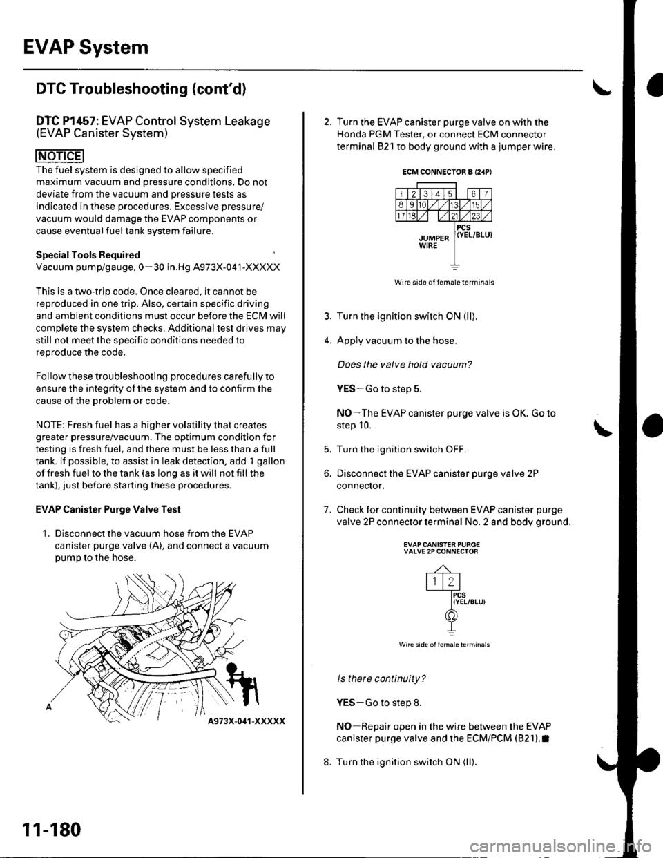
EVAP Canister Purge Valve Test
1. Disconnect the vacuum hose from the EVAP
canister purge valve (A), and connect a vacuumpump to the hose.
11-180
4973X-041-XXXXX
ECM CONNECTOR A I24P'
Wire side of lemale terminals
4.
7.
2. Turn the EVAP canister purge valve on with the
Honda PGM Tester, or connect ECM connector
terminal 821 to body ground with a jumper wire.
Turn the ignition switch ON (ll).
Apply vacuum to the hose.
Does the valve hold vacuum?
YES-Go to step 5.
NO-The EVAP canister purge valve is OK. Go to
step 10.
Turn the ignition switch OFF.
Disconnect the EVAP canister purge valve 2P
conneclor,
Check for continuity between EVAP canister purge
valve 2P connector terminal No. 2 and body ground.
EVAPCANISTEN PURG€VALVE 2P CONNECTOR
-4-
lll2l-fircs
IYEL/8Lu)(f])
I
Wire side offemale lerminals
ls there continuity?
YES-Go to step 8.
NO Repair open in the wire between the EVAP
canister purge valve and the ECM/PCM (821).I
Turn the ignition switch ON (ll).
t
b.
8.
Page 449 of 1139
\
Synchro Sleeve and Hub Inspection
and Reassembly
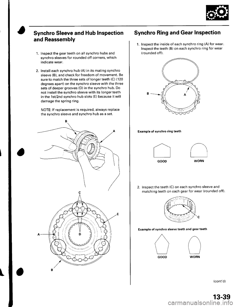
1. lnspectthe gearteeth on ali synchro hubs and
synchro sleeves for rounded off corners, which
indicate wear.
2. Install each synchro hub (A) in its mating synchro
sleeve (B), and check for freedom of movement. Be
sure to match the three sets of longer teeth (C) (120
degrees apart) on the synchro sleeve with the three
sets of deeper grooves (D) in the synchro hub. Do
not install the synchro sleeve with its longer teeth
in the 1sv2nd synchro hub slots (E) because it will
damage the spring ring.
NOTE; lf replacement is required, always replace
the svnchro sleeve and svnchro hub as a set.
Synchro Ring and Gear Inspection
1.Inspect the inside of each synchro ring (A) for wear.
Inspect the teeth (Bi on each synchro ring for wear
(rounded off).
Example of synchro ring teeth
Inspect the teeth (C) on each synchro sleeve and
matching teeth on each gear for wear (rounded off).
Example ofteeth and gear teeth
(cont'd)
I
Il
GOOD
synchro sleeve
GOOD
/\
I
WORN
tl
WORN
13-39
Page 455 of 1139
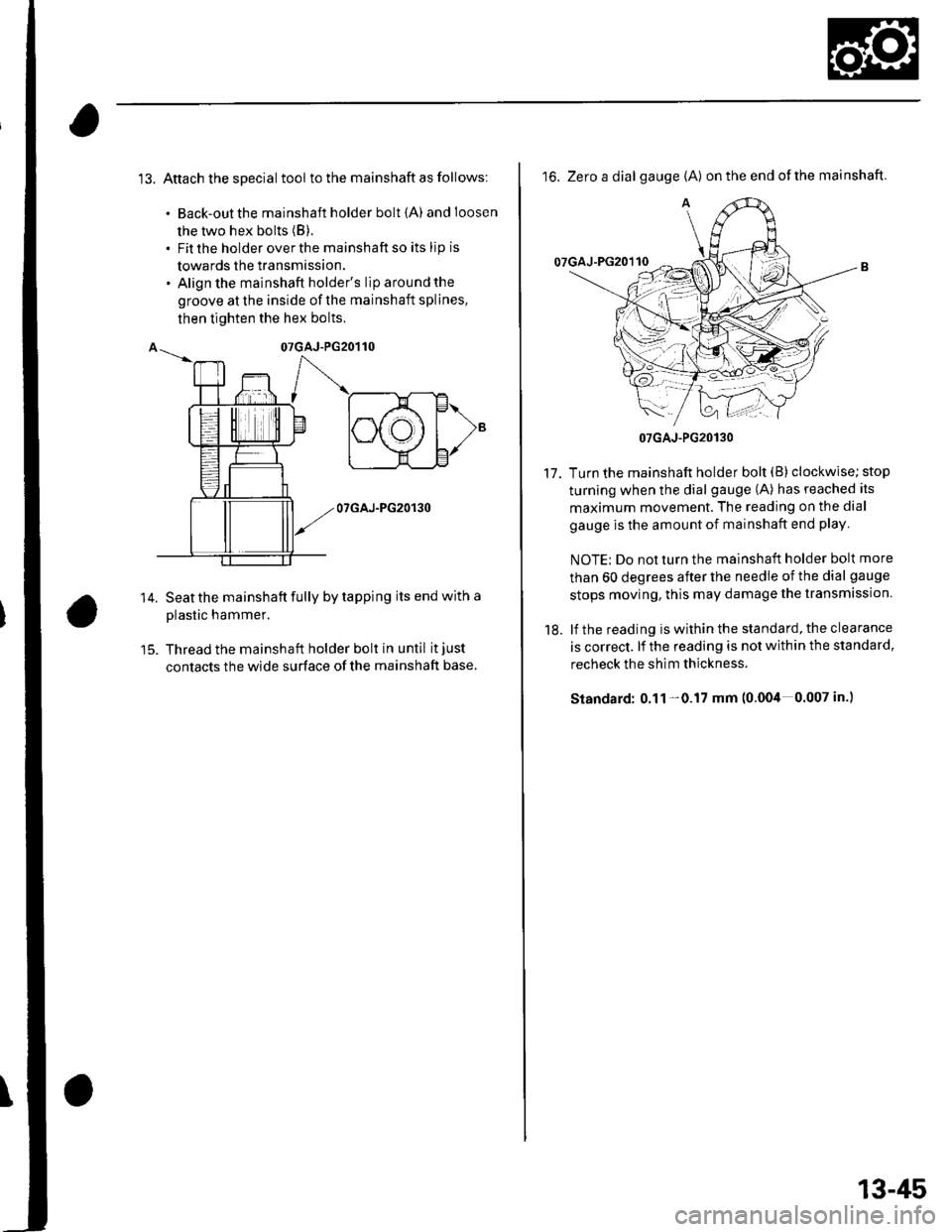
13. Attach the special tool to the mainshaft as follows:
. Back-out the mainshaft holder bolt {A) andloosen
the two hex bolts (B).
. Fit the holder over the mainshaft so its lip is
towards the transmission.. Align the mainshaft holder's lip around the
groove at the inside of the mainshaft splines,
then tighten the hex bolts.
14.
07GAJ-PG20130
Seat the mainshaft fully by tapping its end with a
plastic hammer.
Thread the mainshaft holder bolt in until it just
contacts the wide surface of the mainshaft base.
16. Zero a dial gauge {A) on the end ofthe mainshaft.
Turn the mainshaft holder bolt (B) clockwise; stop
turning when the dial gauge (A) has reached its
maximum movement. The reading on the dial
gauge is the amount of mainshaft end play
NOTE: Do not turn the mainshaft holder bolt more
than 60 degrees after the needle of the dial gauge
stops moving, this may damage the transmission.
lf the reading is within the standard, the clearance
is correct. lf the reading is not within the standard,
recheck the shim thickness.
Standard: 0.11 -0.17 mm (0.004 0.007 in.)
17.
18.
07GAJ-PG20130
13-45
Page 480 of 1139
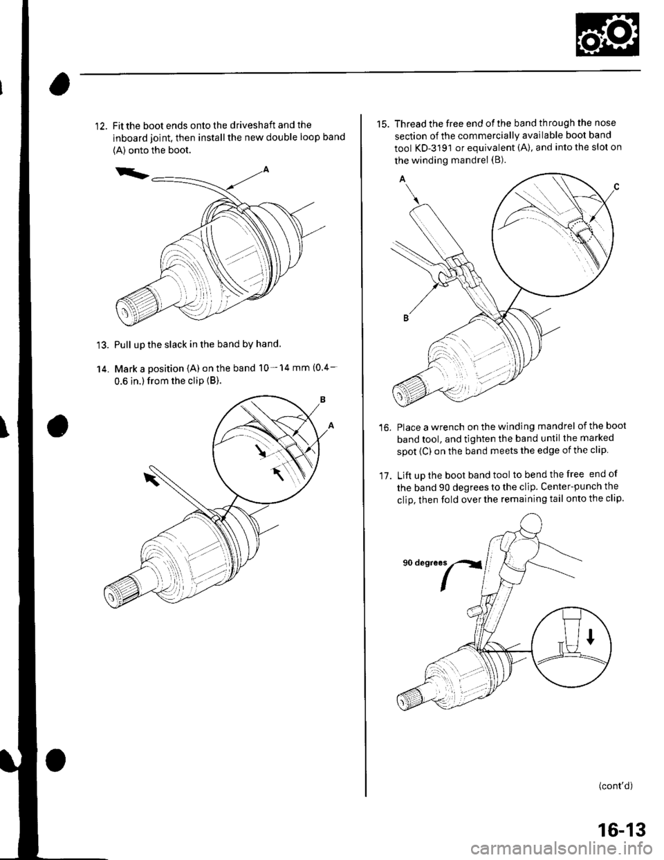
Fit the boot ends onto the driveshaft and the
inboard joint, then install the new double loop band
{A) onto the boot.
Pull up the slack in the band by hand
Mark a position (A) on the band 10- 14 mm (0.4-
0.6 in.) from the clip {B).
15. Thread the free end ofthe band through the nose
section of the commercially available boot band
tool KD-3191 or equivalent (A), and into the slot on
the winding mandrel (B).
Place a wrench on the winding mandrel of the boot
band tool, and tighten the band until the marked
spot (C) on the band meets the edge of the clip
Lift uD the boot band tool tobendthefree end of
the band 90 degrees to the clip. Center-punch the
clio, then fold over the remaining tail onto the clip.
16.
17.
(cont'd)
16-13
Page 509 of 1139
EPS Components
aGeneral Troubleshooting Information
EPS Indicator
Under normal conditions, the EPS indicator comes on when
the ignitlon switch is turned to the ON (ll) position, then goes
off after the engine is started. This indicates that the bulb and
its circuit are operating correctly.
lf there is any trouble in the system after the engine is started,
the EPS indicator will stay on, and the power assist is turned
off.
When EPS indicator light comes on, the control unit
memorizes the DTC. In this case, the control unit will not
activate the EPS system after the engine starts again, but it
keeps the EPS indicator on.
When DTC 12, 16, 17, 18 or 67 is stored in the control unit, the
EPS indicator will stay on until the DTC is erased. When a
problem is detected and the EPS indicator comes on, there are
cases when the indicator stays on untilthe ignition switch is
turned 0FF, and cases when the indicator goes off
automatically when the system returns to normal. Even though
the system is operating normally, the EPS indicator will come
on under the following conditions:
Condition '1:
. The vehicle was traveling at least 12.4 mph (20 km/h), then. A rapid change in vehicle speed was detected, then. The vehicle (or the vehicle speed sensor signal) stopped for
at least 5 seconds. The engine speed was still 'l,640rpmorhigherforatleastS
seconds
Condition 2:
After the vehicle (or the vehicle speed sensor signal) has
stopped for at least 10 seconds, yet the engine speed was still
1,640 rpm or higherfor at least 20 seconds.
Condition 3:
When the engine speed is 280 rpm or less, and the vehicle is traveling at
a speed of 6,2 mph (10 km/h) or more for 3 seconds.
To determine the actual cause ofthe problem, question the
customer about the conditions during which the problem
occured, taking the above conditions into consideration.
Diagnostic Trouble Code (DTCI
. lf the CPU cannot be activated, or itfails,the EPS indicator
comes on, but the DTC is not memorized.. The memory can hold any number of DTCS. However, when
the same DTC is detected more than once, the most recent
DTC is written over the prior DTC, therefore only one
occurrence is memorized.. The DTCS are indicated repeatedly untilthe ignition switch is
turned OFF.. lf the DTC is not memorized,the EPS indicator blinks.
. The DTCS are memorized in the EEPRO| (non-volatile
memory) therefore the memorized DTCS cannot be erased
by disconnecting the battery. Perform the specified
procedures to clear DTCS.
Self-diagnosis
Self-diagnosis can be classified into two categories:.Initial diagnosis: performed right after the engine
starts and until the EPS indicator goes off.. Regular diagnosis: performed right after the initial
diagnosis until the ignition switch is turned OFF.
The EPS control unit performs the following functions
when a problem is detected by self-diagnosis;
'1. Turns on the EPS indicator.
2. Memorizes the DTC.
3. Stops power assist and manual steering operation
begrns.
NOTE:. When DTC 23 (a problem with the circuit for
engine speed signal) is detected, the power
assist will return to normal when the vehicle
speed is 0.62 mph (1 km/h) or above.. Fot DfCs 22,23, 64, or 66 the EPS indicator goes
off automatically when the system relurns to
normal. For all other codes, the EPS indicator
goes off when the system is OK after the ignition
switch is turned from OFF to ON (ll).
Restriction on Power Assist Operation
Repeated extreme steering force. such as turning the
steering wheel continuously back-and-forth with the
vehicle stopped, causes an increase of power
consumption in the EPS motor. The increase of electric
current causes the motor to heat up. Because this heat
adversely affects the system, the control unit monitors
the electric current of the motor.
When the control unit detects heat build-up in the motor,
it reduces the electric current to the motor gradually to
protect the system, and it restricts the power assist
operation. The EPS indicator does not come on during
this function.
When steering torque is not applied to the steering
wheel, or when the ignition is turned off, and the motor
cools, the control unit will restore the power assist
gradually until it's fully restored (after approximately 15
minutes maximum).
17-18
Page 512 of 1139
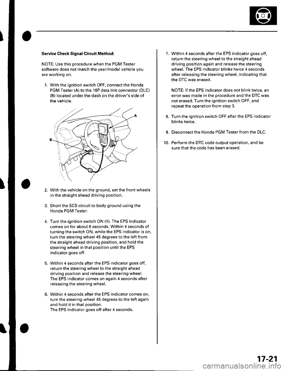
Service Check Signal Circuit Method:
NOTE: Use this procedure when the PGM Tester
software does not match the yearlmodel vehicle you
are working on.
1. With the ignition switch OFF, connect the Honda
PGM Tester (A) to the 16P data link connector {DLC)(B) located under the dash on the driver's side of
the vehicle.
With the vehicle on the ground, set the front wheels
in the straight ahead driving position.
Short the SCS circuit to body ground using the
Honda PGM Tester.
Turn the ignition switch ON (ll). The EPS indicator
comes on for about 6 seconds. Within 4 seconds of
turning the switch ON, while the EPS indicator is on,
turn the steering wheel 45 degrees to the left from
the straight ahead driving position, and hold the
steering wheel in that position until the EPS
indicator goes off.
Within 4 seconds afterthe EPS indicator goes off,
return the steering wheel to the straight ahead
driving position and release the steering wheel.
The EPS indicator comes on again 4 seconds after
releasing the steering wheel,
Within 4 seconds after the EPS indicator comes on,
turn the steering wheel 45 degrees to the left again
and hold it in that position.
The EPS indicator goes off after 4 seconds.
4.
1.Within 4 seconds after the EPS indicator goes off,
return the steering wheel to the straight ahead
driving position again and release the steering
wheel. The EPS indicator blinks twice 4 seconds
after releasing the steering wheel, indicating that
the DTC was erased.
NOTE: If the EPS indicator does not blink twice, an
error was made in the procedure and the DTC was
not erased. Turn the ignition switch OFF, and
repeat the operation from step 3.
Turn the ignition switch OFF afterthe EPS indicator
blinks twice.
9. Disconnect the Honda PGM Tester from the DLC.
10. Perform the DTC code output operation, and be
sure that the code has been erased.
17-21