airbag HONDA CIVIC 2003 7.G User Guide
[x] Cancel search | Manufacturer: HONDA, Model Year: 2003, Model line: CIVIC, Model: HONDA CIVIC 2003 7.GPages: 1139, PDF Size: 28.19 MB
Page 728 of 1139
Seats
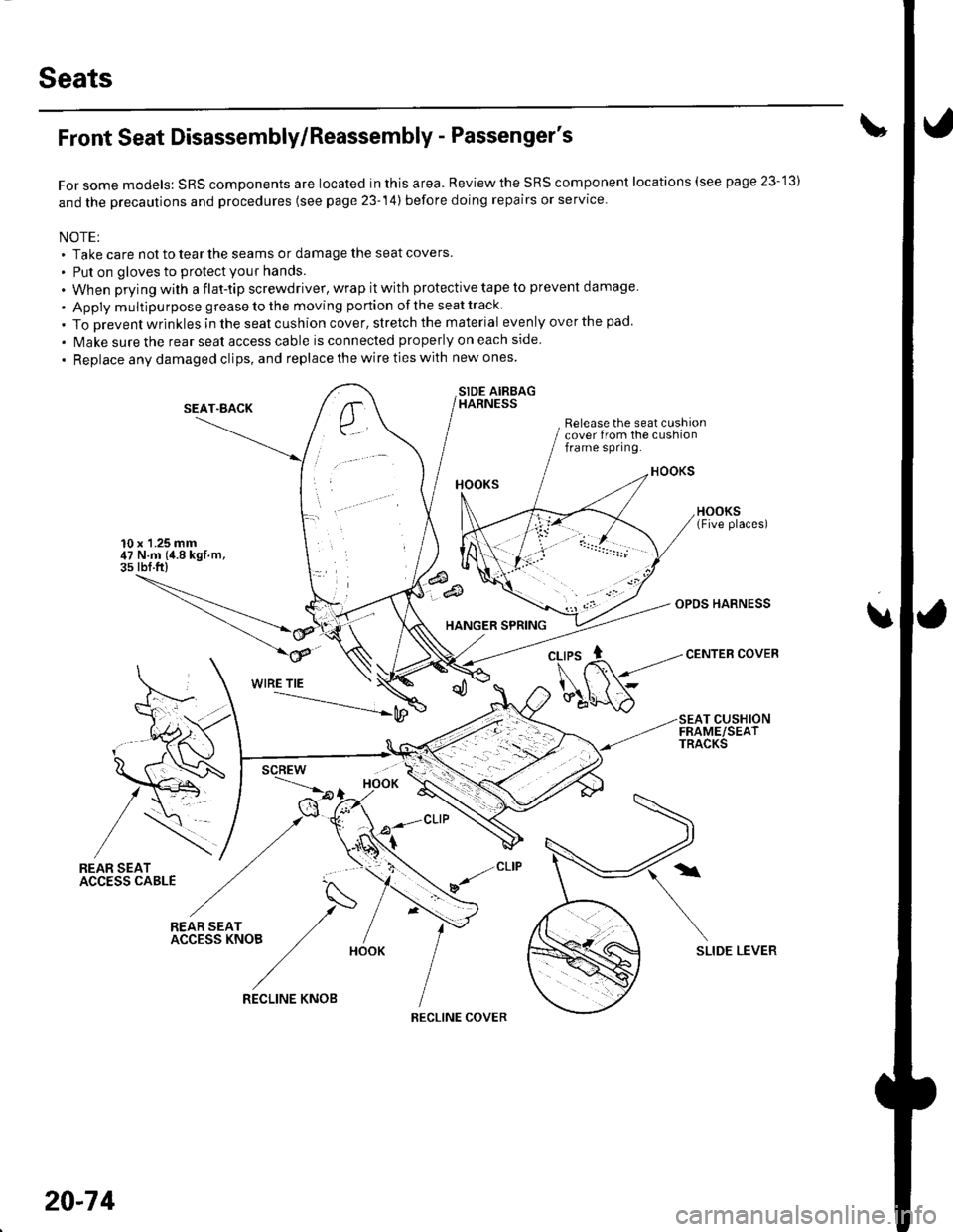
Front Seat Disassembly/Reassembly - Passenger's
For some models: SRS components are located in this area. Reviewthe SRS component locations (see page 23-'13)
and the precautions and procedures (see page 23-14) before doing repairs or service.
NOTE;. Take care not to tear the seams or damage the seat covers
. Put on gloves to protect your hands.
. When prying with a flat-tip screwdriver, wrap it with protective tape to prevent damage
. Apply multipu rpose grease to the moving portion of the seat track
. To Drevent wrinkles in the seat cushion cover, stretch the material evenly over the pad.
. lvlake sure the rear seat access cable is connected properly on each side
. Replace any damaged clips, and replace the wire ties with new ones
SIDE AIRBAGHARNESS
Release the seat cushioncover from the cushionframe spring.
10 x 1.25 mm47 N.m (4.8 kgf.m,3s rbf.ft)
SEAT"BACK
HANGER SPRING
OPDS HARNESS
CENTEB COVER
u
WIRE TIE
SEAT CUSHIONFRAME/SEATTRACKS
/REAR SEATACC€SS CABLE
N
*r(".o, /- IACCESSKNOB ,/ /
/HooK
SLIDE LEVER
,/CLIP
v/
20-74
RECLINE KNOB
RECLINE COVER
Page 729 of 1139
Front Seat Cover Replacement
For some models: SRS components are located in this
area. Review the SRS component locations (see page
23 13) and the precautions and procedures (see page
23-'14) in the SRS section before performing repairs or
service,
NOTE:. Take care not to tear the seams or damage the seat
covers,. On the passenger's seat with side airbag, do not
touch the OPDS sensor in the seat-back pad, and keep
it away from oil. Oil can corrode the sensor causing it
to fail.. Put on gloves to protect your hands.
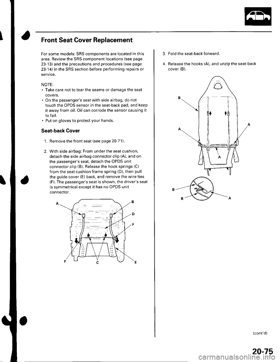
Seat-back Cover
Remove the front seat isee page 20-71).
With side airbag: From under the seat cushion,
detach the side airbag connector clip (A), and on
the passenger's seat, detach the OPDS unit
connector clip (B). Release the hook springs (C)
from the seat cushion frame spring {D), then pull
the guide cover (E) back, and remove the wire ties
(F). The passenger's seat is shown, the driver's seat
is svmmetrical except it has no OPDS unit
connector.
'L
2.
3.Fold the seat-back forward.
Release the hooks (A), and unzip the seat-back
cover (B).4.
(cont'd)
20-75
Page 731 of 1139
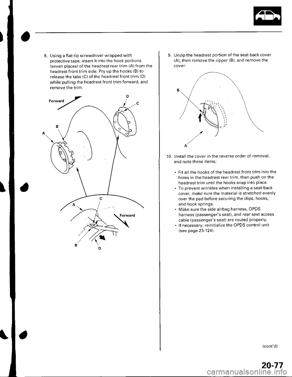
8.Using a flat-tip screwdriver wrapped with
protective tape, insert it into the hook portions
(seven places) ofthe headrest rear trim iA) from the
headrest front trim side. Prv up the hooks (B) to
release the labs (C) of the headrest front trim (Di
while pulling the headrest front trim forward, and
remove the tflm.
D
/
10.
9. Unzip the headrest portion of the seat-back cover
(A), then remove the zipper iB), and remove the
cover.
A
installthe cover in the reverse order of removal,
and note these items:
. Fit all the hooks of the headrest front trim into the
holes in the headrest rear trim, then push on the
headrest trim until the hooks snap into place.
. To prevent wrinkles when installing a seat back
cover, make sure the material is stretched evenly
over the pad before securing the clips, hooks,
and hook springs.. Make sure the side airbag harness, OPDS
harness {passenger's seat). and rear seat access
cable (passenger's seati are routed properly.
. lf necessary, reinitialize the OPDS control unit
(see page 23-124).
(cont'd)
20-77
Page 732 of 1139
Seats
Front Seat Cover Replacement {cont'd)
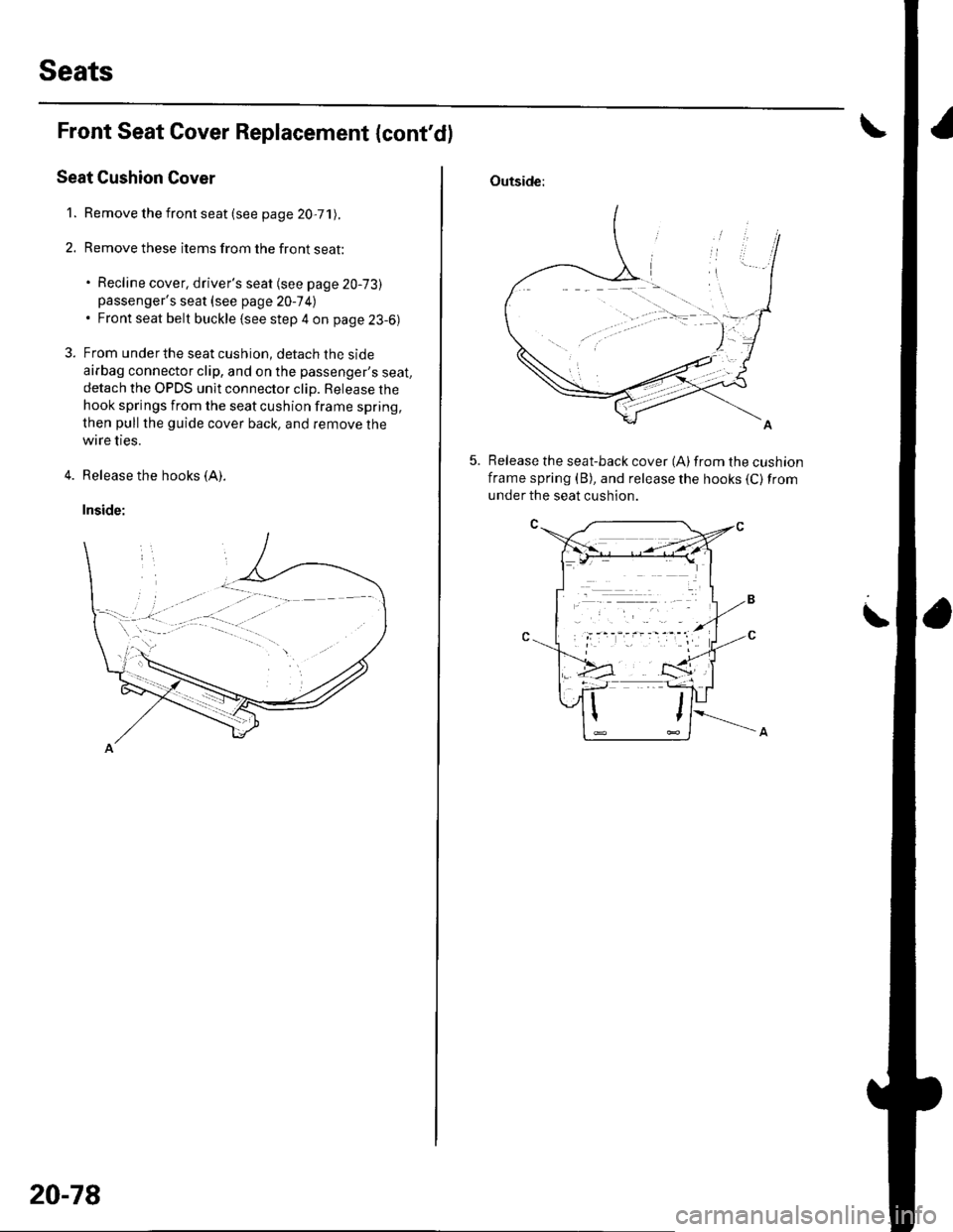
Seat Cushion Cover
1. Remove the front seat (see page 20,71).
2. Remove these items from the front seat:
. Recline cover, driver's seat (see page 20-73)passenger's seat {see page 20-7 4l. Front seat belt buckle {see step 4 on page 23-6)
3. From underthe seat cushion, detach the side
airbag connector clip, and on the passenger's seat,detach the OPDS unit connector clip. Release the
hook springs from the seat cushion frame spring,
then pull the guide cover back, and remove the
wire ties.
4. Release the hooks (A).
Inside:
20-78
Outside:
Release the seat-back cover (A)from the cushion
frame spring (B), and release the hooks (C) from
under the seat cushion.
Page 733 of 1139
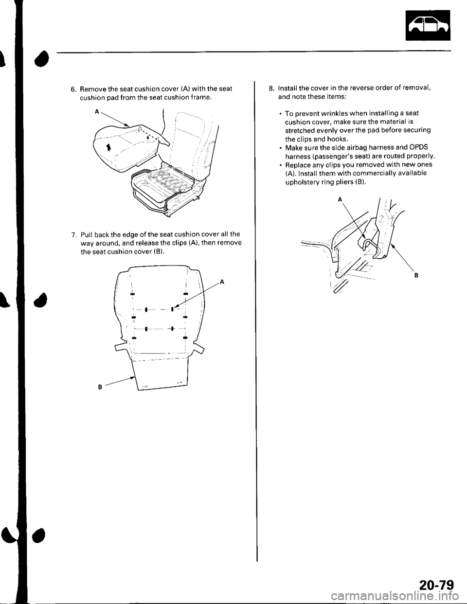
6. Remove the seat cushion cover (A) withtheseat
cushion pad from the seat cushion frame.
Pull back the edge of the seat cushion cover all the
way around. and release the clips {A), then remove
the seat cushion cover (B).
1.
r {, ]
:F+r
r* ?
8. Installthe cover in the reverse order of removal,
and note these items;
. To prevent wrinkles when installlng a seat
cushion cover, make sure the material is
stretched evenly over the pad before securing
the clips and hooks.. Make sure the side airbag harness and OPDS
harness (passenger's seat) are routed properly.
. Replace any clips you removed with new ones
(A). Installthem with commercially available
upholstery ring pliers (B).
20-79
Page 849 of 1139
Connectors and Harnesses
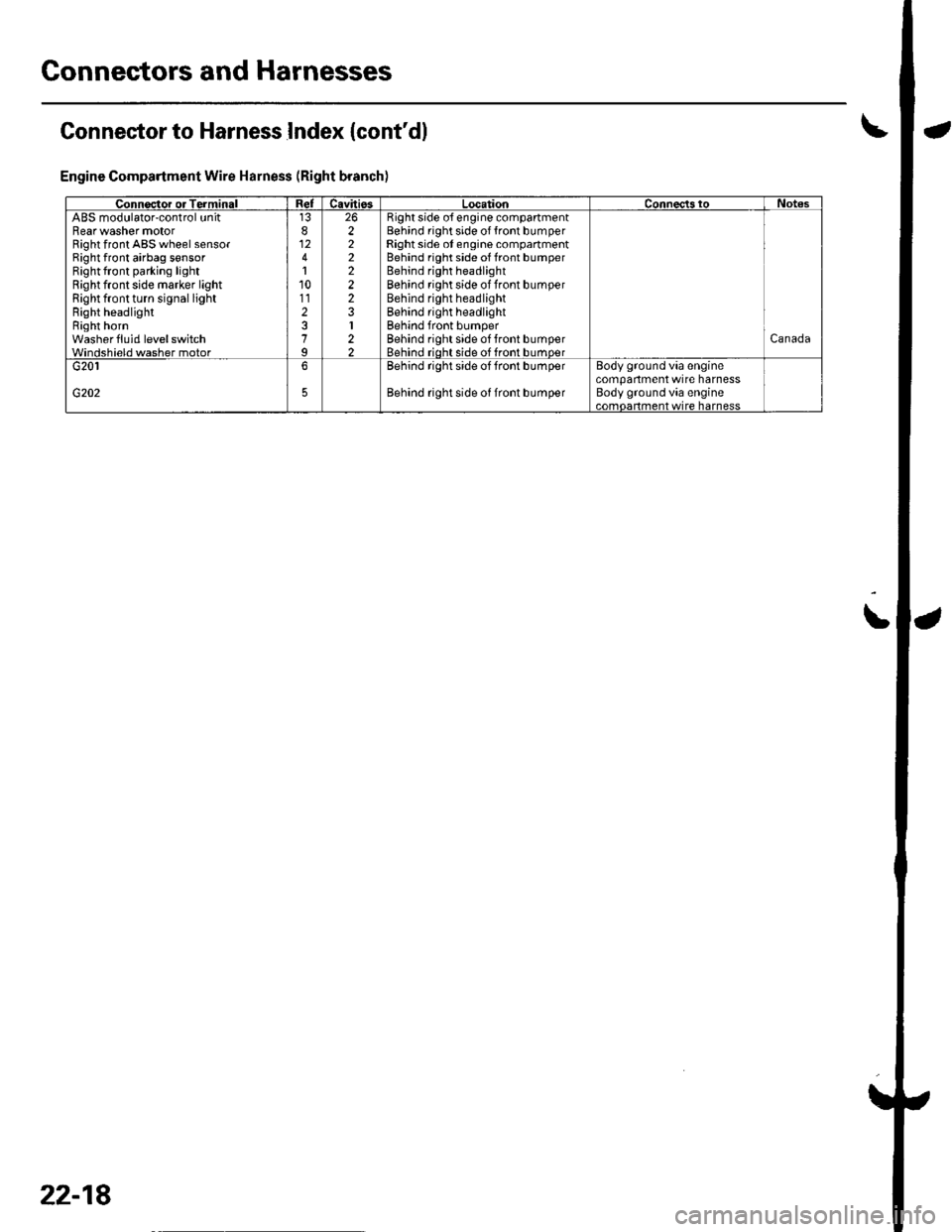
Connector to Harness Index {cont'dl
Engine Compartment Wire Harness (Right branch)
\
Connsctor or TerminalCavitissLocationConnects toNotesABS modulator-control unitBearwasher motorRight front ABS wheel sensorRight front airbag s€nsorBightfront parking lightRight front side marker lightRight front turn signal lightRight headlightRight hornwash€rfluid level switchWindshield washer motor
812
110112
7
222222
I22
Bight side o{ engine compartmentBehind right side of {ront bumperRight side ot engine compartmentBehind right side of front bumperBehind right headlightBehind rightside of Jront bumperBehind right headlightBehind right headlightBehind front bumperBehind rightside of tront bumperBehind rioht side of front bumoerCanada
G202
G2016Behind rightside of tront bumper
Behind rightside of Jront bumper
Body ground via €nginecompartment wtre harnessBody ground via engine.omnerhent wire harness
22-18
Page 851 of 1139
Connectors and Harnesses
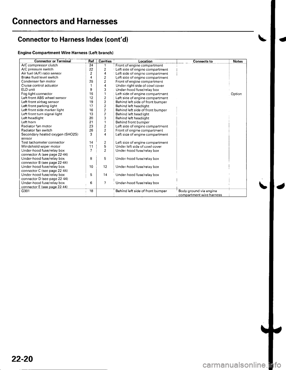
Engine Compartment Wire Harness (Left branch)
AirJuel (A,,/F) ratio sensorBrake fluid level switchCondenser fan motorCruise control actuatorELD unitFog light connectorLeft front ABS wheel sensorLeft front airbag sensorLeft front parking lightLeft front side marker lightLeft lrontturn signal lightLeft headlightLeft hornRadiator fan motorRadiator fan switchSecondary heated oxygen (SHO2S)
Test tachometer connectorWindshield wiper motorUnder'hood fuse/relay boxconnector A {see page 22-44)Under-hood f use/relay boxconnector B (see page 22-44)Under hood fuse/relay boxconnector C (see page 22-44)Under hood fuse/relay boxconnector D (see page 22 44)Under-hood fuse/relay box
Front of engine companmentLeft side of engine compartmentLeft side of engine compartmentLeft side o{ engine compartmentFront of engine compartmentUnder right side of cowl coverUnder'hood f use/relay boxLeft side of engine compartmentLeft side of engine companmentBehind left side of front bumperBehind left headlightBehind left side of front bumperEehind left headlightBehind left headlightBehind front bumperLeft side of engine compartmentFront of engine compartmentLeft side of engine compartment
Left side of engine companmentL.Jnder left side of cowl coverL.Jnder hood fuse/relay box
L.Jnder hood fuse/relay box
L.Jnder'hood f use/relay box
underhood fuse/relay box
Under-hood fuse/relay box
24222
2519
12
17
13202123
3
117
I
10
5
6
l2
2243,l
222223l224
252
5
12
Connector to Harness Index (cont'dl
\
22-20
Page 861 of 1139
Connectors and Harnesses
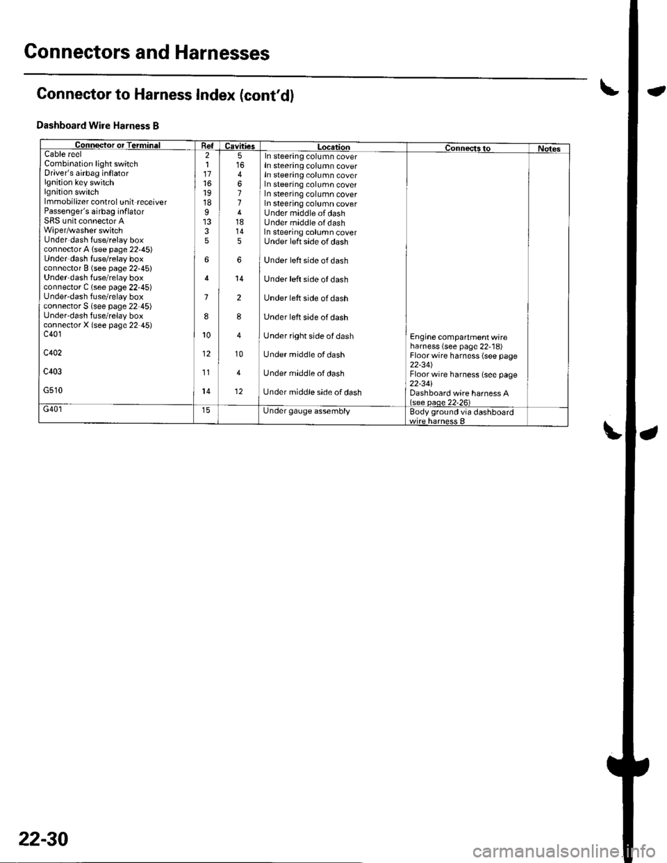
Connector to Harness Index (cont'd)
Dashboard Wire Harness B
Collqctor or TerminalCavitiesLocatiol|ConnectstoNotesCableCombination light switchDriver's airbag inflatorlgnition key switchlgnition switchlmmobilizer control unit receiverPassenger's airbag inf latorSRS unit connector AWiper/washer switchUnder dash fuse/relay boxconnectorA lsee page 22,45)Under dash luse/relay boxconnector B (see page 22-45)Under'dash fuse/relay boxconnector C (see page 22-45)Under-dash fuse/relay boxconnector S lsee page 22-45)Under'dash fuse/relay boxconnectorX (see page 22 45)c401
c402
c403
G510
reel211716't9
18I
35
6
1
8
10
12
11
14
5
4
11418145
6
14
2
8
10
4
12
In steering column coverIn steering column coverIn steering column coverIn steering column coverIn steering column coverIn steering column coverUnder middle of dashUnder middle ofdashIn steering column coverUnder left side of dash
Under left side ofdash
Under left side of dash
Under lett side of dash
Under left side of dash
Under right side of dash
Under middle of dash
Under middle of dash
Under middle side of dash
Engine compartment wireharness (see page 22-'18)Floor wire harness (see page22-34JFloor wire harness (see page22-341Dashboard wire harness A(see oaoe 22-26)G40lUnder gauge assemblyBody ground via dashboard
22-30
Page 865 of 1139
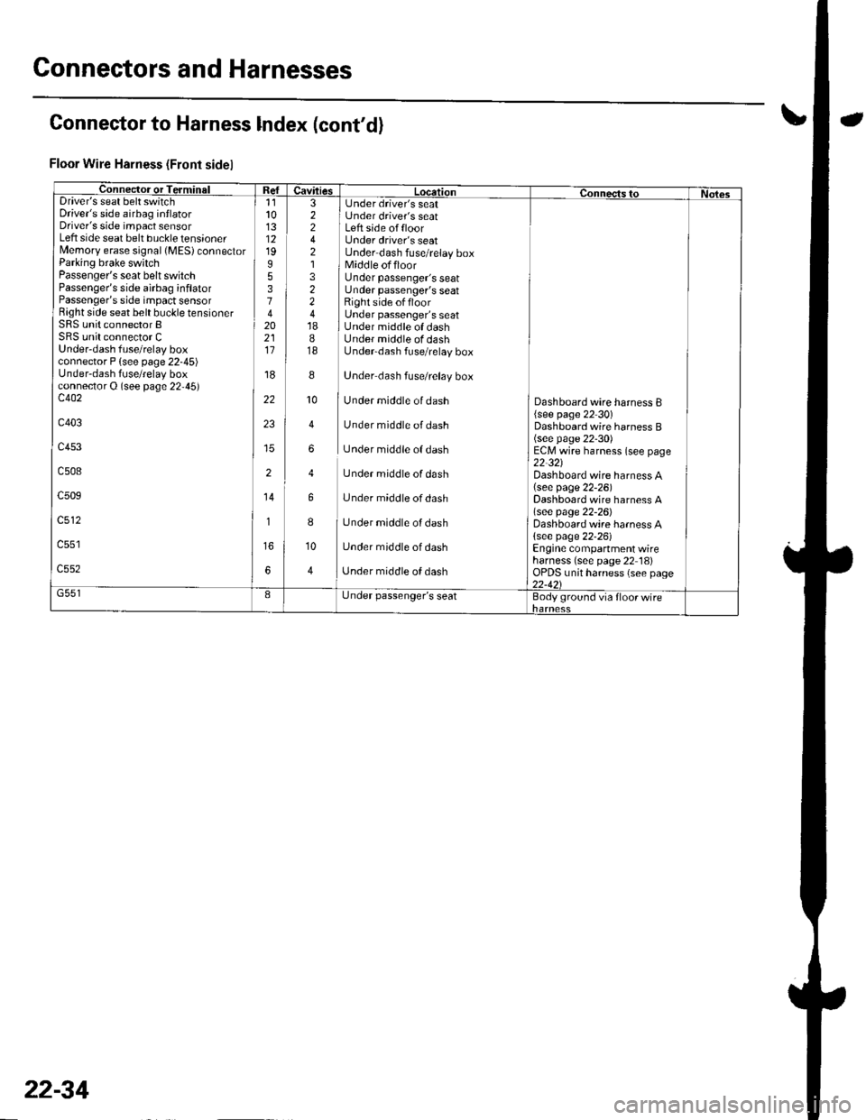
Connectors and Harnesses
Connector to Harness lndex (cont'd)
Floor Wire Harness (Front sidel
Connec-tor or TerminalI Refuavftres Location connects to Nol6sDriver's seat belt switchDriver's side airbag inflatorDriver's side impact sensorLeft side seat belt buckle tensionerMemory erase signal (MES) connectorParking brake switchPassenger's seat belt switchPassenger's side airbag inflatorPassenger's side impact sensorRight side seat belt buckle tensionerSRS unit connector BSRS unit connector CUnder-dash fuse/relay boxconnector P {see page 22-45)Under-dash fuse/relay boxconnector O (see page 22,45)c402
c403
c453
c508
c509
c512
11l013121995374202111
'r8
22
23
2
14
1
6
3 I Under driver's seat2 i Under driver's seat2 I Left side offloor4 Under driver's seat2 Under dash fuse/relay box1 1 Middle offloor3 Under passenger's seat2 Under passenger's seat2 Right side offloor4 Under passenger's seat18 I Under middle of dash8 Under middle of dash18 Underdash fuse/relay box
8
]
Under dash fuse/relay box
10
I
Under middle of dash
4 Under middle of dash
6 Under middle of dash
4 Under middle of dash
6 Under middle ofdash
8
I
Under middle of dash
10 Under middle of dash
4 ] Unaer middle of aasn
Dashboard wire harness B{see page 22 30)Dashboard wire harness B(see page 22-30)ECM wire harness (see page22-321Dashboard wire harness A(see page 22-26)Dashboard wire harness A\see page 22-26)Dashboard wire harness A{see page 22-26)Engine compartment wireharness (see page 22 18)OPDS unit harness (see page22-421G551IL,nder passenger's seatBody ground via floor wire
22-34
Page 1009 of 1139
I
I
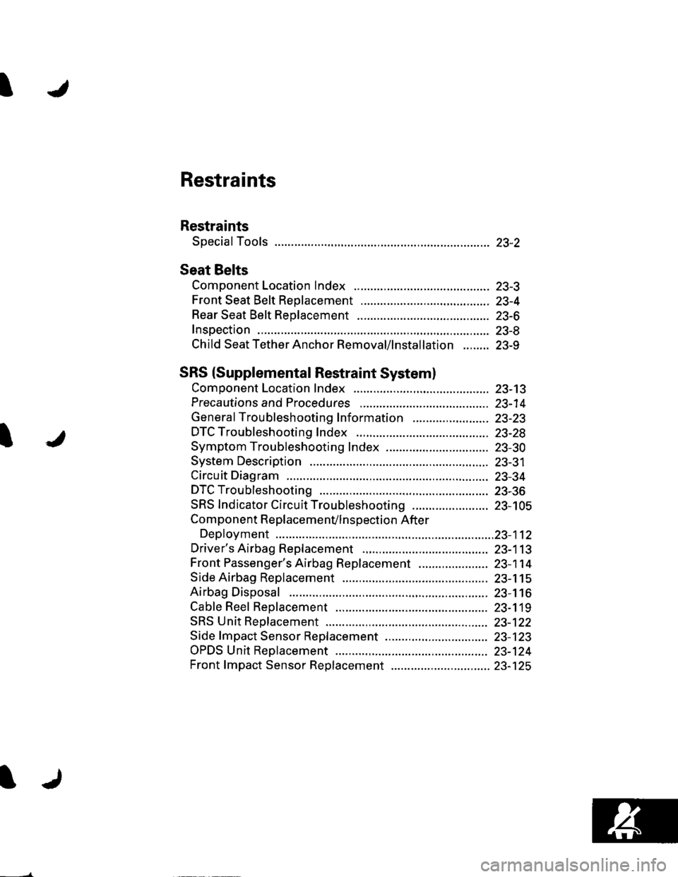
Restraints
Restraints
Special Tools ............. 23-2
Seat Belts
Component Location Index ......................................... 23-3
Front Seat Belt Replacement ....................................... 23-4
Rear Seat Belt Replacement ........................................ 23-6
Inspection .................. 23-8
Child Seat Tether Anchor Removal/lnstallation ........ 23-9
SRS (Supplemental Restraint Systeml
Component Location Index ......................................... 23-13
Precautions and Procedures ,,.,......... 23-14
General Troubleshooting Information ....................... 23-23
DTC Troubleshooting Index .............. 23-28
Symptom Troubleshooting Index ............................... 23-30
System Description ................. ........... 23-31
Circuit Diagram ......... 23-34
DTC Troubleshooting ............... .......... 23-36
SRS Indicator Circuit Troubleshooting ....................... 23-105
Component R e place me n(/ln s pect io n After
Deployment ..............23-112
Driver's Airbag Replacement ............ 23-113
Front Passenger's Airbag Replacement ..................... 23-1 14
Side Airbag Replacement .................. 23-115
Airbag Disposal ....................... ........... 23-116
Cable Reel Replacement .................... 23-119
SRS Unit Repfacement ....................... 23-122
Side fmpact Sensor Replacement ..........,.................... 23-123
OPDS Unit Replacement .................... 23-124
Front fmpact Sensor Replacement .............................. 23-125