airbag HONDA CIVIC 2003 7.G Owners Manual
[x] Cancel search | Manufacturer: HONDA, Model Year: 2003, Model line: CIVIC, Model: HONDA CIVIC 2003 7.GPages: 1139, PDF Size: 28.19 MB
Page 1124 of 1139
)
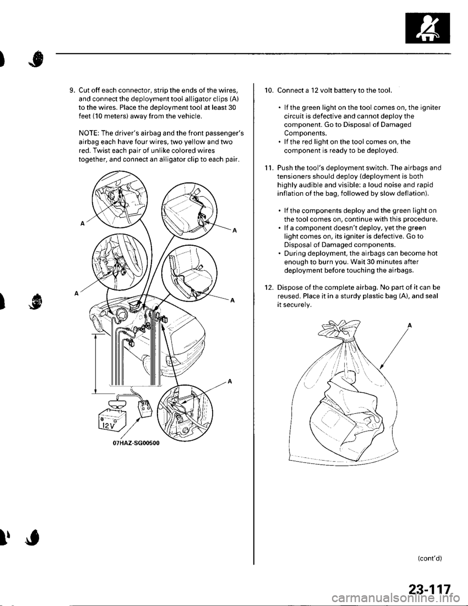
9. Cut off each connector, strip the ends of the wires,
and connect the deployment tool alligator clips (A)
to the wires. Place the deployment tool at least 30
feet (10 meters) away from the vehicle.
NOTE: The driver's airbag and the front passenger's
airbag each have four wires, two yellow and two
red. Twist each Dair of unlike colored wires
together, and connect an alligator clip to each pair.
I
!
10. Connect a 12 volt battery to the tool.
. lf the green light on the tool comes on, the igniter
circuit is defective and cannot deDlov the
component. Go to Disposal of Damaged
ComDonents.. lf the red light on the tool comes on, the
component is ready to be deployed.
11. Push the tool's deployment switch. The airbags and
tensioners should deploy (deployment is both
highly audible and visible: a loud noise and rapid
inflation of the bag, followed by slow deflation).
. lf the components deploy and the green light on
the tool comes on, continue with this procedure.
. lf a component doesn't deploy, yet the green
light comes on, its igniter is defective. Go to
Disposal of Damaged components.. During deployment, the airbags can become hot
enough to burn you. Wait 30 minutes after
deployment before touching the airbags.
12. Dispose ofthe complete airbag. No pan of it can be
reused. Place it in a sturdy plastic bag (A), and seal
rt securery.
(cont'd)
/:
i'..-':
23-117
Page 1125 of 1139
sRs
Airbag Disposal (cont'dl
Deploying Components Out of the Vehicle
lf an intact airbag or tensioner has been removed from
a scrapped vehicle, or has been found defective or
damaged during transit, storage, or service, it should be
deoloved as follows:
1. Confirm that the special tool isfunctioning properly
by following the check procedure on this page or
on the tool label.
2. Position the airbag face up, outdoors, on flat
ground, at least 30 feet (10 meters) from any
obstacles or DeoDle.
3. Follow steps 9 through 1 1 of the in-vehicle
deployment procedure.
Disposal of Damaged Components
1. lf installed in a vehicle, follow the removal
procedure for the driver's airbag (see page 23-113),
front passenger's airbag (see page 23-114), side
airbag (see page 23-115). seat belt tensioner (see
page 23-4), and seat belt buckle tensioner.
2. In all cases. make a short circuit by cutting,
stripping, and twisting together the two inflator
wires.
NOTE; The driver's and passenger's airbag each
have four wires: twist each pair of like-colored
wires together
Package the component in the same packaging that
the new reolacement Dart came in.
Mark the outside of the box "DAMAGED AIRBAG
NOT DEPLOYED'" ''DAMAGED SIDE AIRBAG NOT
DEPLOYED", "DAMAGED SEAT BELT TENSIONER
NOT DEPLOYED" or "DAlvlAGED SEAT BELT
BUCKLE TENSIONER NOT DEPLOYED" so it does
not get confused with your parts stock.
Contact your Honda District Service Manager for
how and where to return it for disposal.
23-118
I|J
J
Deployment Tool Check
1. Connect the yellow clips to both switch protector
handles on the tool; connect the tool to a battery.
2. Push the operation switch: green means the tool is
OK; red means the tool is faulty
3. Disconnectthe battery and the yellow clips.
J
Page 1126 of 1139
)
3.
4.
Cable Reel Replacement
Removal
1. Make sure the front wheels are aligned straight
ahead.
Disconnect the battery negative cable, and wait at
least 3 minutes.
Remove the driver's airbag {see page 23-113).
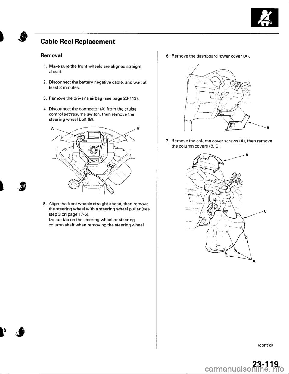
Disconnect the connector (Al from the cruise
control sevresume switch, then remove the
steering wheel bolt (B).
Align the front wheels straight ahead, then remove
the steering wheel with a steering wheel puller (see
step 3 on page '17-6).
Do not tap on the steering wheel or steering
column shaftwhen removing the steering wheel.
)
5.
I,
6. Remove the dashboard lower cover (Ai.
Remove the column cover screws (A), then remove
the column covers (8, C).
7.
(cont'd)
23-119
Page 1128 of 1139
)
Install the steering column covers.
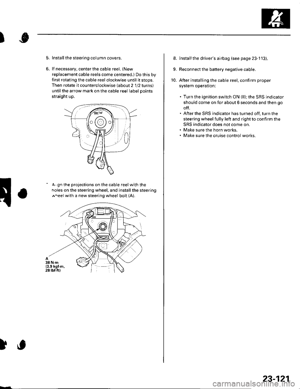
lf necessary, center the cable reel. {New
replacement cable reels come centered.) Do this by
first rotating the cable reel clockwise until it stops,
Then rotate it counterclockwise labout 2 1 12 lurns)
untilthe arrow mark on the cable reel label Doints
straight up.
- A gn the projections on the cable reel with the
noles on the steering wheel, and installthe steering
Ai\eel with a new steering wheel bolt (A).
)c
23-121
8. lnstallthe driver's airbag (see page 23-113).
9. Reconnect the battery negative cable.
10. After installing the cable reel, confirm proper
syslem operalton:
. Turn the ignition switch ON (ll); the SRS indicator
should come on for about 6 seconds and then go
off.. After the SRS indicator has turned off, turn the
steering wheel fully left and right to confirm the
SRS indicator does not come on.. Make sure the horn works.. Make sure the cruise control works,
Page 1129 of 1139
sRs
SRS Unit Replacement
Removal
'1. Disconnect the battery negative cable, and wait at
least 3 minutes before beginning work.
2. Disconnect the driver's and front passenger's
airbag connectors (see page 23-21).
3. Disconnectthe side airbag connectors (see page
23-211.
4.Disconnect both seat belt tensioner connectors (see
page 23-22) and both seat belt buckle tensioner
connectors {see page 23-221.
Remove the dashboard center lower cover (see
step 2 on page 20-57).
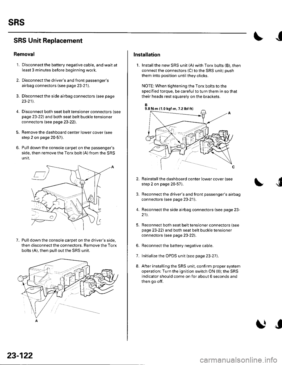
Pull down the console carpet on the passenger's
side, then remove the Torx bolt (A)from the SRS
unit.
7. Pull down the console carpet on the driver's side,
then disconnect the connectors. Remove the Torx
bolts (A), then pull out the SRS unit.
23-122
lnstallation
1, Installthe new SRS unit (A)with Torx bolts (B), then
connect the connectors {C) to the SRS uniu push
them into position until they clicks.
NOTE: When tightening the Torx bolts to the
specified torque, be careful to turn them in so that
their heads rest squarely on the brackets.
Reinstall the dashboard center lower cover (see
step 2 on page 20-57).
Reconnect the driver's and front passenger's airbag
connectors (see page 23-21]'.
Reconnect the side airbag connectors (see page 23-
211.
Reconnect both seat belt tensioner connectors (see
page 23-221 and both seat belt buckle tensioner
connectors (see page 23-22).
Reconnect the battery negative cable.
Initialize the OPDS unit (see page 23'27).
After installing the SRS unit, confirm proper system
operation: Turn the ignition switch ON (ll); the SRS
indicator should come on for about 6 seconds and
then go off.
4.
6.
8.
7.
9.8 N.m (1.0 kgf m, 7.2 lbf ft)
Page 1130 of 1139
)
)
Side lmpact Sensor Replacement
Removal
1. Disconnect the battery negative cable, and wait at
least 3 minutes before beginning work.
2. Disconnect the appropriate side airbag 2P
connector (see step 4 on page 23-21).
3. Remove the seat assembly (see pa ge 20-71J.
4. Remove the front door silltrim and the B-pillar
lower trim panel (see page 20-50).
5. Disconnect the floor wire harness 2P connector
from the side impact sensor.
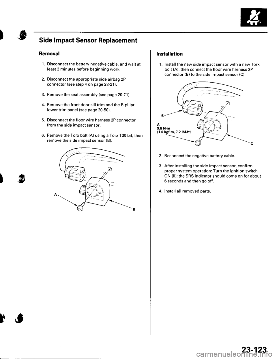
6. Remove the Torx bolt (A) using a Torx T30 bit, then
remove the side impact sensor (B).
)
lnstallation
1. Install the new side impact sensor with a new Torx
bolt (A), then connect the floor wire harness 2P
connector {B) to the side impact sensor {C).
2.
3.
Reconnect the negative battery cable.
After installing the side impact sensor, confirm
proper system operation:Turn the ignition switch
ON (ll); the SRS indicator should come on for about
6 seconds and then go off.
Install all removed parts.
23-123
Page 1131 of 1139
sRs
OPDS Unit Replacement
NOTE: Review the seat replacement procedures in the
body section before performing repairs or service.
Removal
1. Disconnect the battery negative cable. and wait at
least 3 minutes before beginning work.
2. Disconnect the passenger's side airbag harness 2P
connector (see step 4 on page 23-2'll.
3. Remove the front passenger's seat assembly (see
page 20-71)and seat-back cover (see page2O-15],.
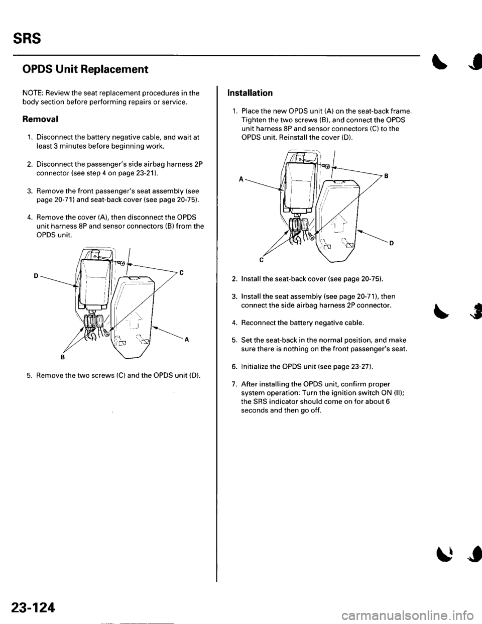
4. Remove the cover (A), then disconnect the OPDS
unit harness 8P and sensor connectors (B) from the
OPDS unit.
5. Remove the two screws (C) and the OPDS unit (D).
23-124
Installation
1. Place the new OPDS unit (A) on the seat-back frame.
Tighten the two screws (B), and connect the OPDS
unit harness 8P and sensor connectors (C) to the
OPDS unit. Reinstallthe cover (D).
2.
4.
1.
Installthe seat-back cover (see page 20-75).
Install the seat assembly (see page 20-71), then
connect the side airbag harness 2P connector,
Reconnect the battery negative cable.
Set the seat-back in the normal position, and make
sure there is nothing on the front passenger's seat.
Initialize the OPDS unit (see page 23-27).
After installing the OPDS unit, confirm proper
system operation: Turn the ignition switch ON (ll);
the SRS indicator should come on for about 6
seconds and then go off.
Page 1132 of 1139
)
1.
Front lmpact Sensor Replacement
Removal
Disconnect the battery negative cable. and wait at
least 3 minutes before beginning work.
Disconnect the driver's airbag 4P connector lsee
step 2 on page 23-21), the front passenger's airbag
4P connector (see step 3 on page 23-21), both seat
belt tensioner 2P connectors (see step 5 on page
23-221, and both seat belt buckle 4P connectors (see
step 6 on page 23-22).
Remove the front inner fender (see pag e 2O-1O21.
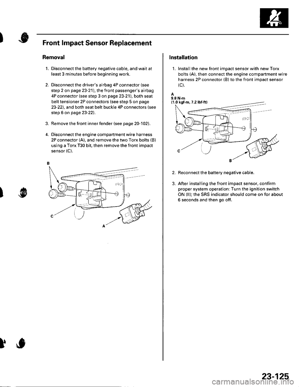
Disconnect the engine compartment wire harness
2P connector (A), and remove the two Torx bolts (B)
using a Torx T30 bit, then remove the front impact
sensor {C).
2.
)
)
Installation
1. Installthe new front impact sensor with new Torx
bolts (A), then connect the engine compartment wire
harness 2P connector (B) to the front impact sensor
{c).
A9.8 N.m
Reconnect the battery negative cable.
After installing the front impact sensor, confirm
proper system operation: Turn the ignition switch
ON (ll); the SRS indicator should come on for about
6 seconds and then go off.
(1.0 kgf.m,7.2lbf.ftl
23-125
Page 1133 of 1139
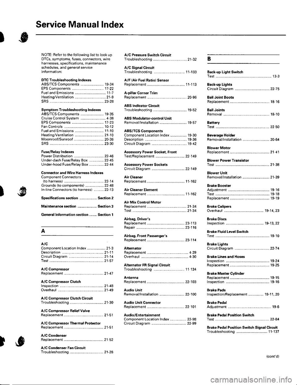
Service Manual lndex
)s
NOTE: Referto the lollowing listto look up A/C Pressure Switch CircuitDTCS, symptoms, fuses, connectors, wire Troubleshooting ......... ...-.-....-...-.-.-....-..21-32 Bharnesses, specifications, maintenanceschedules, and general serviceinlormation:
DTC Troubleshooting Indexes
A/C Signal CircuitTroubleshooting.........................-...... 11-'133 Back-up Light SwitchTest .......................................................... 13'3A/F lAir Fuel Ratiol SensorABS/TCS Components ........................ 19-34 Replacement ....................................... 1 1-113 Back-up Li9ht3EPS Components ................................. '17-22 Circuit DiagramFueland Emissions11-i A-Dillar Corner Trim
ABS Indicator Circuit
Heating/Ventilation ................................ 21-9 Replacement ...............-.....-..............-.... 20,96 Ball Joint BootssRS ........................................................ 23-28Replacement ......
... 19-52 Ball Joints
22-75
18 16
Remova1.............-.......... . ...........18-10Symptom Troubleshooting Indexes TroubleshootingABS/TCSComponents........................ 19 35Cruise Control System ..........................4 38 ABS Modulator-contml UnitEPS Components ................................. 17-23 Bemoval/lnstallation ............................ 19-57 BettervFan Controls10,12
Accessory Powor Socket Front
Blowor Pow€r Transistor
.......22 50
Blower UnitRemoval/lnstallation ............................ 21-39
Fuel and Em issions .............................. 11-10 ABS/TCS ComoonentsHeating/Ventilation..............................21 10 Component Location Index ................. 19-30 Beverage Holder
SRS ........................................................ 23'30 CircuitDiaqram.......................... 19'42Blower MotorReplacement .....21 41
21-38
Power 0istribution ...............................22-46 TesVReplacement .............................. 22'149Under-dash Fuse/Relay Box ............... 22 45Under-hood Fuse/Belay Box ...............22 44 Accessory Power Sockets
Fuse/Relay lndexes
(to harness)
Connector and Wire Harness lndexesComponent Connectors
Circuit Oiagram .................................. 22-149
Air Cleaner......2214 Rep1acemen1.....................................11-162
Air MixControl MotorMeintenence section .................... Section 3 Replacement ......................................... 21'34 Brake CelipersTest......................21-34 Overhaul19-14,23Gene.al lnlormation section........ Section 1
21.57
Airbag. Driver's
Ahernator FR Signal CircuitTroubleshooting .... .........-..........11 134
AntennaReplacement
Inspection ............................................. 19-24Rep|acement................. .................... 19-25
Bieke Meder Cylinder
Irake Discs
A
Replacement ....................................... 23 1 'l3 Inspection .................... ................... 19-13,22Repair ...........-...................................... 23 1 16Brake Fluid Level SwitchAirbag. Front Passenger's TestBeplacement....................................... 23-1 14AIC Brake LightsComponent Location fndex ...................21-3 Altemator CircuitDiagram....................................22-74Description.....................................-....21'1'l Beplacement ................ ........................... 4 29CircuitDiagram....................................21-14 Overhaul .................................................4-30 Brake Lines and Hoses
19.10
A/C CompressolReplacement .......-...-............................. 21 -41
A/C Compr€ssor ClulchRep1acement......................................... 19-15.........22-103 Inspection ............................................. 19-16Inspecton........Overhaul ..........
A/C CondenserReplacement,.,
21-442l-49 Audio Unit
Replacement
Brake PadsRemoval/lnstallation .. ........................22-100 Inspection/Rep1acement................ 19-11,20A/C Compressor Clutch CircuitTroubleshooting ................................... 21-30 Audio Unit Connector Brake Pedal22101 Adjustment..............19,6ArfC Comoressor Relief ValvcReplacement ..........-...-.......................... 21-51 Audio/Entertainment
A/C Compr$sor Thermal Protector Circuit DiagramReplacement............-............................ 21-51
Component Location In dex .................22-9A Test .......-.............. 22-84Breke Pedal Posilion Switch
Brake Pedal Position Switch Signal Clrcuit11-137
.....21 52
A/C Condenser Fan CircuitTroubleshooting ................... . . . . . .....21-28
)s
Troubleshooting
(cont'd)
Page 1138 of 1139
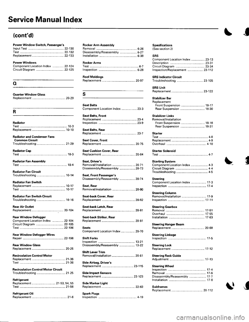
Service Manual lndex
(cont'dl
Power Window Switch, Passenger'slnput Test .............-......
Replacement...,-.-.-...,..
Radialor Cap
Rocker Arm AssemblyRemovalD;sassembly/Reassembly
Specifications6-26 (See section 2)22-13022 13222-133..................... 6-27
ComponentLocation Index ..............22 124Circuit Dia9ram .................. ............... 22 125
Ouaner Window Glass8ep1acement ......................................... 20-29
lnstallation6-38
Rocker ArmsTestInspecton6-28
Roof MoldingsReplacement
Seat BeltsComponent Location Index ................... 23-3
Seat 8ehs, FrontReplacementrnspec!on
sRsComponent Location Index ................. 23-13Description ....................................... 23-31Circuit D;agram ... .... ...........2334lnspection/Replacemenl ................... 23 1 126-7
SRS lndicator CircuilTroubleshooting
Startel
Stabilizer BarReplacementFront SuspensionRear Suspension
Stabilizer LinksRemoval/lnstallationFront SuspensionRear Suspension
23 105oSRS UnitReplacement..-.................................... 23-122s
R
1A-1718-30
18 1818-31RadiatorTest......23-9
23-1Replacement ...........
Radiator and Condenser FansCommon CircuitTroubleshooling......... ..... .........21 29
10-310-10Seat Behs, RearReplacement
Seat Cover, FrontReplacement
Seat Cushion Cover, R6ar10-3Replacement
ReplacementTest
Test
20-75
20-84
Overhaul
Starter SolenoidTest..-.-...4-7
Radiator Fan AssemblyTestSeat, Driver'sRemovaf/lnstaf lation ............................ 20 1 1Disassembly/Reassemb1y ................... 20-73
Sedt, Faont Passenger'sDisassembly/Reassemb1y ................... 20-74
Seat, RearRemoval/lnstallation ............................ 20-80
Seat-back Cover, Reer
Starting SystemComponent Location Index...............-..... 4-3CircuitDia9ram ........................................ 4 4
\'{........................ r0-4
Radiator Fan CircuitTroubleshooting
Radiator Fan SwhchReplacementTest
Radiator Fan Switch CircuitTroubleshooting
Rear Air OutletReplacement
Circuil DiagramTest
Rear Window D€rogger WiresRepair
RearWindow GlassReplacement
Troubleshooting10-14
10-1710-17
10 16
17 -3
11-4
17-9
SteeringComponent Location Index................-..Inspectaon ...................
Steering ColumnRemoval/lnstallationReplacementInspection11 11
17-5117 5517 63
20 68
Seat-back Latch, ReaI2Q-104Replacement
Seat-back Striker. RearReplacement
Steering GearboxRemovalOverhaulRear Window DefoggerComponentLocalion Index ..............22 104lnstallation
Steering Hanger BeamReplacement
Steering LinkageInspefiron
Steering LockReplacement
Steering Rack GuideAdiustment
22-10522 106
22-106
SeatsComponent Location Index....-............ 20-70
Shift ForksInspectton13,21
20-25
2l-3621 36
21 25
Disassembly/Reassembly ................... 13-22
Shitt Lever TrimRemoval/lnstallation ............................ 20 61
.....11-12
SecirculationReplacementControl Motor17-13Test.....
Recirculation Control Motor CircuitTroubleshooting
Side Airbag, Drivel'sReplacement
Side lmpact SensorsReplacement
Spark Plugs
23-115
23 123
Side Marker LightRep1acement......................................... 22-A3
17417-6Disassembly/Reassembly ..................... 17 71nsta11ation .............................................. 17-8
SublramesReplacement
Removal
RefrigerantReplacement ..-.-.-...................... 21 53, 54, 55Test ........................................................ 21-56
Retrigerant OilReplacement...............................-........... 21-6. .._..4_19
20 112