diagram HONDA CIVIC 2003 7.G User Guide
[x] Cancel search | Manufacturer: HONDA, Model Year: 2003, Model line: CIVIC, Model: HONDA CIVIC 2003 7.GPages: 1139, PDF Size: 28.19 MB
Page 240 of 1139
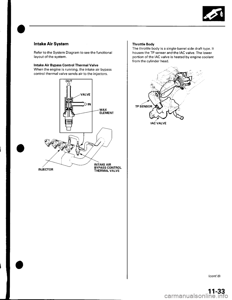
Intake Air System
Refer to the System Diagram to see the functional
layout of the system.
Intake Air Bypass Control Thermal Valve
When the engine is running, the intake air bypass
control thermal valve sends air to the iniectors,
INJECTOR
Throttle Body
The throttle body is a single-barrel side draft type. lt
houses the TP senser and the IAC valve. The lower
portion of the IAC valve is heated by engine coolant
from the cylinder head.
IAC VALVE
{cont'd)
11-33
Page 242 of 1139
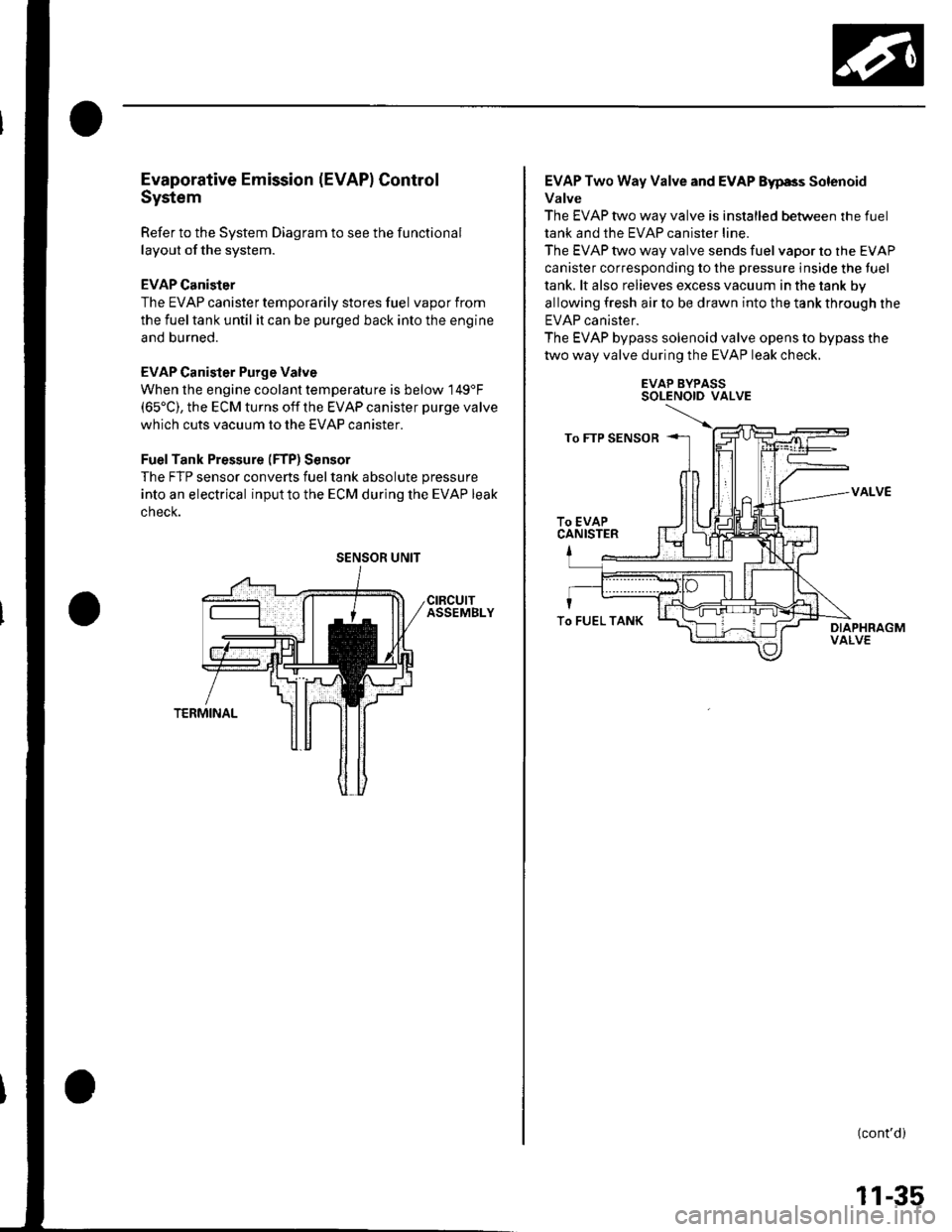
Evaporative Emission (EVAPI Control
System
Refer to the System Diagram to see the functional
layout of the system.
EVAP Canister
The EVAP canister temporarily stores fuel vapor from
the fuel tank until it can be purged back into the engine
and burned.
EVAP Canister Purge Valve
When the engine coolant temperatu re is below 149'F(65'C), the ECM turns off the EVAP canister purge valve
which cuts vacuum to the EVAP canister.
FuelTank Pressure (FTP) Sensor
The FTP sensor converts fueltank absolute pressure
into an electrical inputto the ECM during the EVAP leak
cnecK.
SENSOR UNIT
EVAP Two Way Valve and EVAP Eyp8s Solenoid
Valve
The EVAP two way valve is installed between the fuel
tank and the EVAP canister line.
The EVAP two way valve sends fuel vapor to the EVAP
canister corresponding to the pressure inside the tuel
tank. lt also relieves excess vacuum in the tank by
allowing fresh air to be drawn into the tank through the
EVAP canister.
The EVAP bypass solenoid valve opens to bypass the
two way valve during the EVAP leak check.
EVAP BYPASSSOLENOID VALVE
VALVE
(cont'd)
To FUEL TANK
11-35
Page 243 of 1139
Fuel and Emissions Systems
System Descriptions (cont'dl
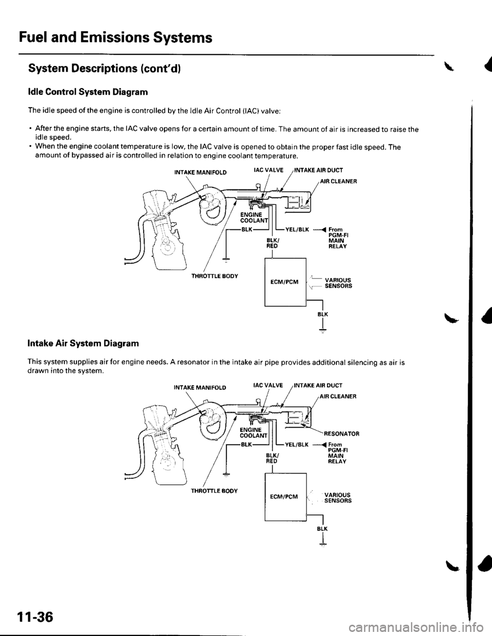
ldle Control System Diagram
The idle speed of the engine is controlled by the ldle Air Control (lAC) varve:
'Aftertheenginestarts,theIACvalveopensforacertainamountoftime.Theamountofairisincreasedtoraisethe
idle sDeed.. When the engine coolant temperature is low, the IAC valve is opened to obtain the proper fast idle speed. Theamount of bypassed air is controlled in relation to engine coolant temperature.
INTAKE MANIFOLDIAC VALVEAKE AIR DUCT
CLEANER
\
BLK/REO
YEL/BLK ---< FromPGM.FIMAINRELAY
THROTTLE AODY
Intake Air System Diagram
This system supplies air for engine needs. A resonator in the intake air
drawn into the svstem.
VARIOUSSENSOnS
pipe provides additional silencing as air is
THROTTLE AODYVARIOUSSENSORS
BLK
BLK
I
11-36
{
Page 244 of 1139
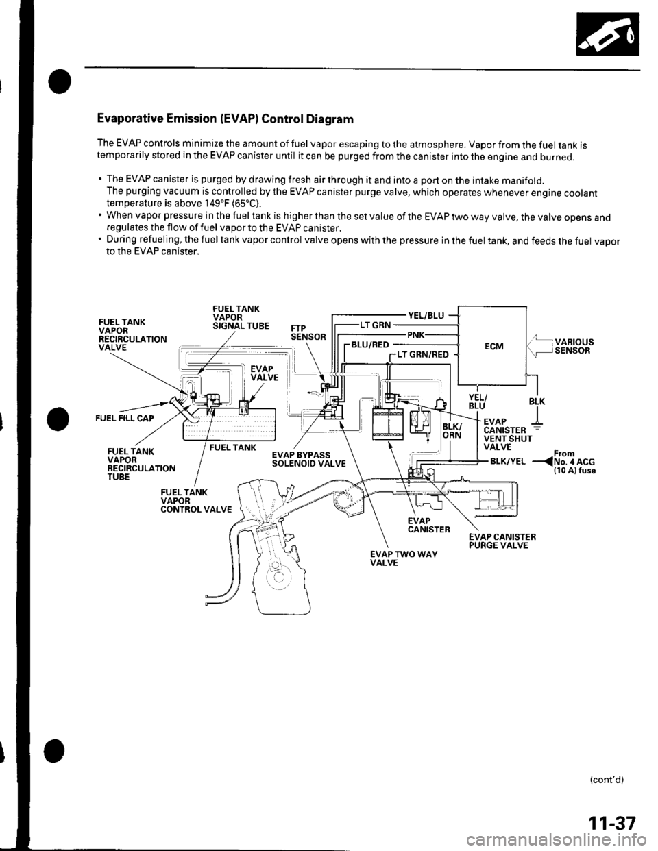
Evaporative Emission (EVAPI Control Diagram
The EVAP controls minimize the amount of fuel vapor escaping to the atmosphere. Vapor from the fuel tanK rstemporarily stored in the EVAP canister until it can be purged from the canister into the engine and burneo.
. The EVAP canister is purged by drawing fresh air through it and into a port on the intake manifold.The purging vacuum is controlled by the EVAP canister purge valve, which operates whenever engine cootanttemperature is above 149'F (65"C).
'WhenvaporpressureinthefueltankishigherthanthesetvalueoftheEVAPtwowayvalve,thevalveopensano
regulates the flow of fuel vapor to the EVAP canister.'Duringrefueling,thefueltankvaporcontrol valve opens with the pressure in the fuel tank, and feeds the fuel vaDorto the EVAP canister.
FUEL TANKVAPORRECIRCULATIONVALVE
FUEL TANKVAPORSIGNAL TUBE
BLU/RED
FUEL FILL CAP
BLK
+EVAPCANISTER
FUEL TANKVENT SHUTVALVE
BLK/YELFrom--
EVAPCANISTER
EVAP TWO WAYVALVE
(cont'd)
11-37
Page 245 of 1139
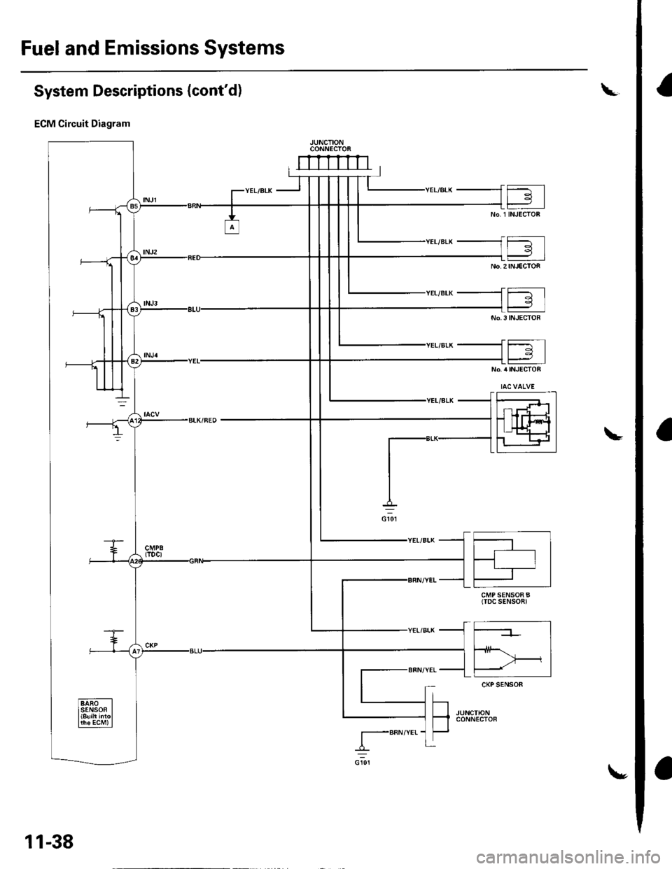
Fuel and Emissions Systems
I
a
a
System Descriptions (cont'd)
ECM Circuit Diagram
CONNECTOi
mrrrrn
CMP SENSOR B(TDC SENSOn)
I-BRN/YEr-
11-38
\,
Page 247 of 1139
![HONDA CIVIC 2003 7.G User Guide Fuel and Emissions Systems
System Descriptions (contdl
ECM Circuit Diagram {contd)
\
-{ffi]---1t-|
IATSENSOR
-{El------l
ECTSENSOS
T_""",,..
I-BFN/YEL
ft^--l
,","., J t-|:I REVERSEI LocKI soleloto+ HONDA CIVIC 2003 7.G User Guide Fuel and Emissions Systems
System Descriptions (contdl
ECM Circuit Diagram {contd)
\
-{ffi]---1t-|
IATSENSOR
-{El------l
ECTSENSOS
T_""",,..
I-BFN/YEL
ft^--l
,","., J t-|:I REVERSEI LocKI soleloto+](/img/13/5744/w960_5744-246.png)
Fuel and Emissions Systems
System Descriptions (cont'dl
ECM Circuit Diagram {cont'd)
\
-{ffi]---1t-|
IATSENSOR
-{El------l
ECTSENSOS
T_""",,..
I-BFN/YEL
ft^--l
,","., J t-|':I REVERSEI LocKI soleloto+ vaLvE
t!j]]
CMPSENSOAA
L-IJUNCTIONI CONNECTOR
-
11-40
Page 249 of 1139
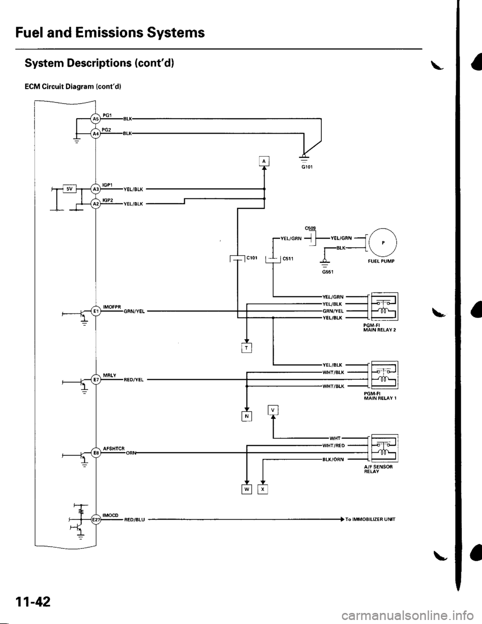
Fuel and Emissions Systems
a
a
a
System Descriptions (cont'd)
ECM Circuit Diagram lcont'dl
IGP2
YEI/BLK
VET/BLK
---rF-rl-lF-forl--JliD\l
--t-l
MAIN BETAV 2
t_,",
f-"'*'o""
tr
:tl-,r'l r,
-,u-
I SENSOS
11-42
IMMOAIL|zER UNIT
Page 251 of 1139
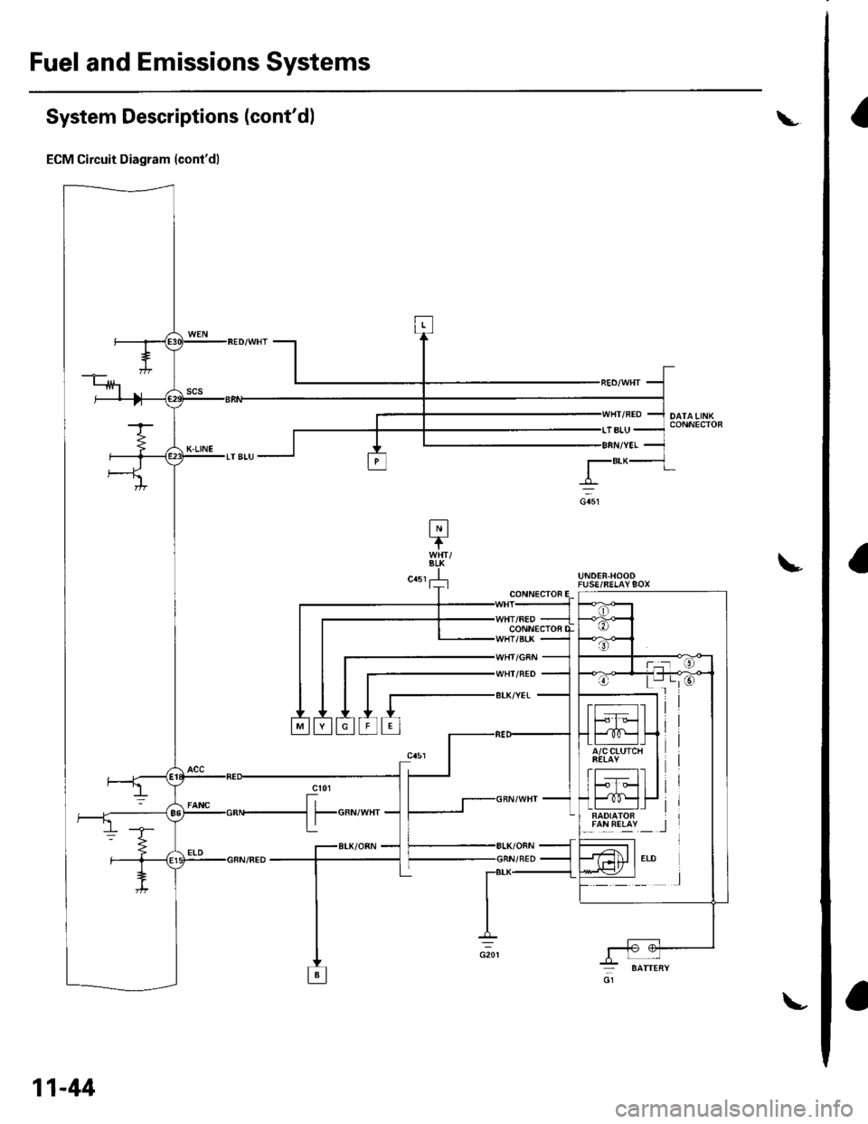
Fuel and Emissions Systems
a
System Descriptions (cont'dl
ECM Circuit Diagram (cont'd)
L
!UNDER.HOODFUSE/RELAY9OX
lalLREllY _ _l
CONN€CTOF
CONNECTOi
WHI/NED
BLK/YET
11-44
Page 363 of 1139
Fuel Supply System
Fuel Gauge Sending Unit Test
Special Tools Required
Fuel sender wrench 07XAA-001010A
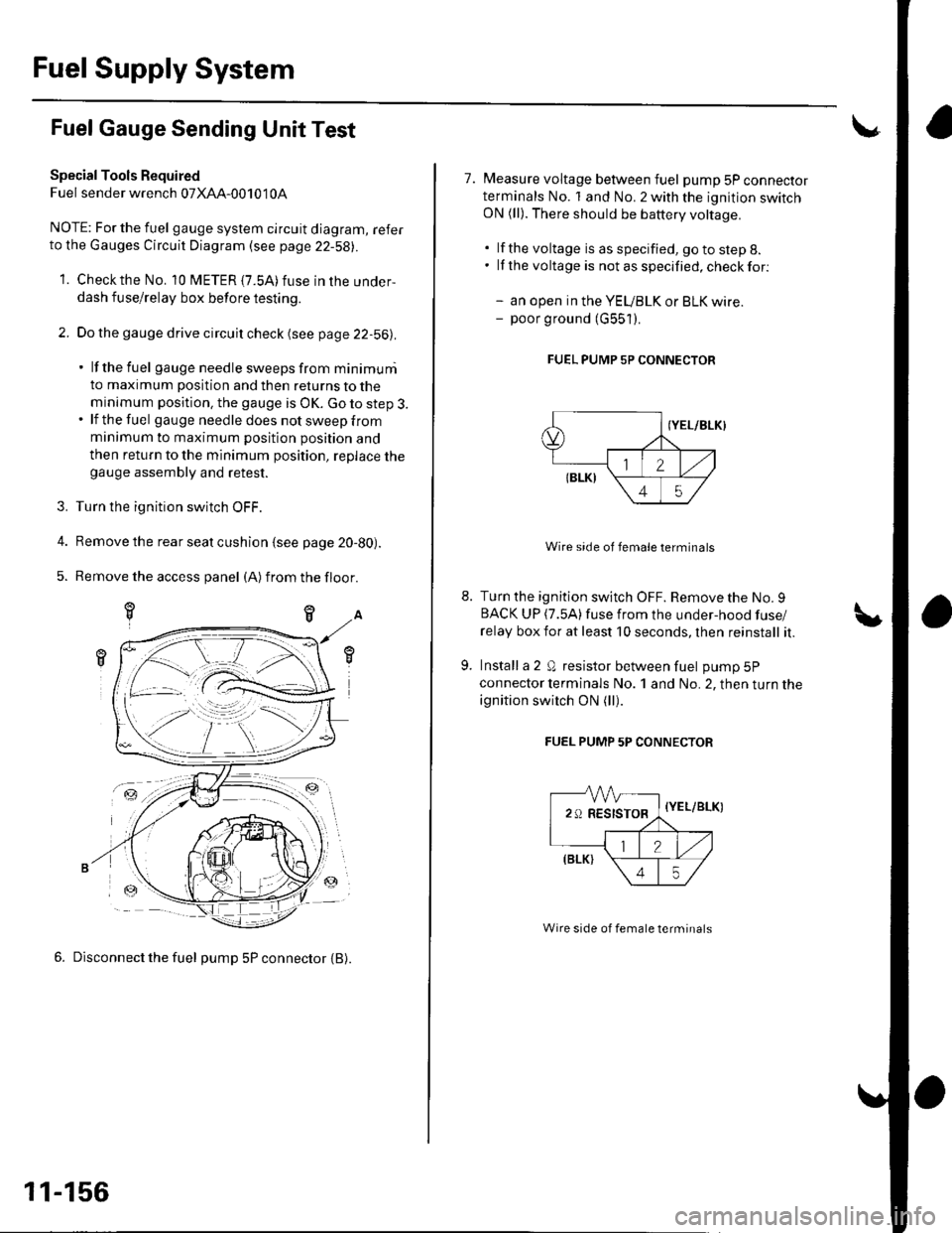
NOTE; For the fuel gauge system circuit diagram, referto the Gauges Circuit Diagram (see page 22-58||.
1. Checkthe No. 10 fUETER {7.5A)fuse in the under-
dash fuse/relay box before testing.
2. Do the gauge drive circuit check (see page 22-56|l.
' lf the fuel gauge needle sweeps from minimuni
to maximum position and then returns to the
minimum position. the gauge is OK. Go to step 3.. lf the fuel gau ge need le does not sweep from
minimum to maximum position position and
then return to the minimum position, replace thegauge assembly and retest.
3. Turn the ignition switch OFF.
4. Remove the rear seat cushion {see page 20-80).
5. Remove the access panel (A)from the floor.
6. Disconnect the fuel pump 5P connector {B).
-ztr
11-156
7. Measure voltage between fuel pump 5P connectorterminals No. 1 and No. 2 with the ignition switchON (ll). There should be battery voltage.
. lf the voltage is as specified, go to step 8.. lf the voltage is notasspecified,checkfor:
- an open in the YEUBLK or BLK wire.- poor ground (G551).
FUEL PUMP 5P CONNECTOR
Wire side of female terminals
Turn the ignition switch OFF. Remove the No. 9BACK UP (7.5A)fuse from the under-hood fuse/
relay box for at least 10 seconds, lhen reinstall it.
Install a 2 Q resistor between fuel pump 5P
connector lerminals No. 1 and No. 2, then turn the
ignition switch ON (ll).
FUEL PUMP 5P CONNECTOR
-VVV-
29RESISTOR,
=-a
{Y
\
//,(elrt \
\45/
{YEL/BLK)
Wire side of female terminals
Page 365 of 1139
Fuel Supply System
1.
4,
Low Fuel Indicator Test
Do the fuel gauge sending unit test (see page 11,
rcol.
. lf the system is OK, go to step 2.. lf the system has any malfunction, repair it.
Turn the ignition switch OFF. Remove the No. 9
BACK UP (10A) fuse from the under-hood fuse/
relay box for at least 30 seconds, then reinstall it.
Turn the ignition switch ON (ll) with the float at the
E (EMPry) position.
. lf the low fuel indicator is on, go to step 4.. lf the low fuel indicator is not on, refer to the low
fuel indicator Circuit Diagram (see page 22-58)
and check the circuit.
Turn the ignition switch OFF. Remove the No. 9
BACK UP (10A) fuse from the under-hood fuse/
relay box for at least 30 seconds, then reinstall it.
Lift the float above the LOW position.
. lf the lowfuel indicatorgoes off,the system is OK.. lf the low fuel indicator is still on, refer to the low
fuel indicator Circuit Diagram {see page 22-58),
and check the circuit.
11-158
\,