fuse box HONDA CIVIC 2003 7.G User Guide
[x] Cancel search | Manufacturer: HONDA, Model Year: 2003, Model line: CIVIC, Model: HONDA CIVIC 2003 7.GPages: 1139, PDF Size: 28.19 MB
Page 83 of 1139
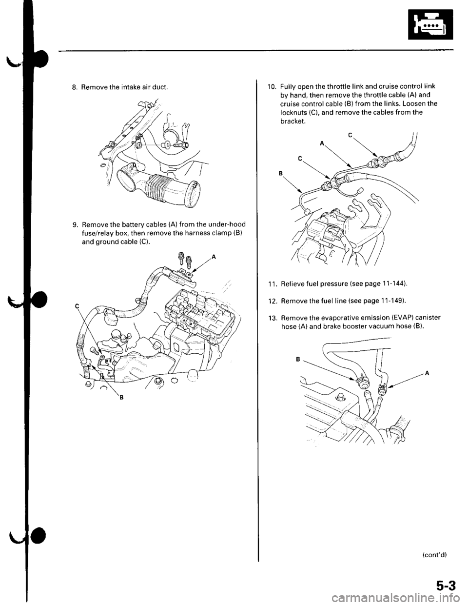
8. Remove the intake air duct.
9. Remove the battery cables {A) fromthe under-hood
fuse/relay box. then remove the harness clamp (B)
and ground cable (C).
10. Fullv ooen the throttle link and cruise control link
by hand, then remove the throttle cable (A) and
cruise control cable (B)from the links. Loosen the
locknuts {C), and remove the cables from the
bracket.
11. Relievefuel pressure (see page 11-144).
12. Remove the fuel line(seepagell-149).
13. Remove the evaporative emission (EVAP) canister
hose {A) and brake booster vacuum hose (B).
(cont'd)
5-3
Page 94 of 1139
Engine Assembly
Engine Installation {cont'dl
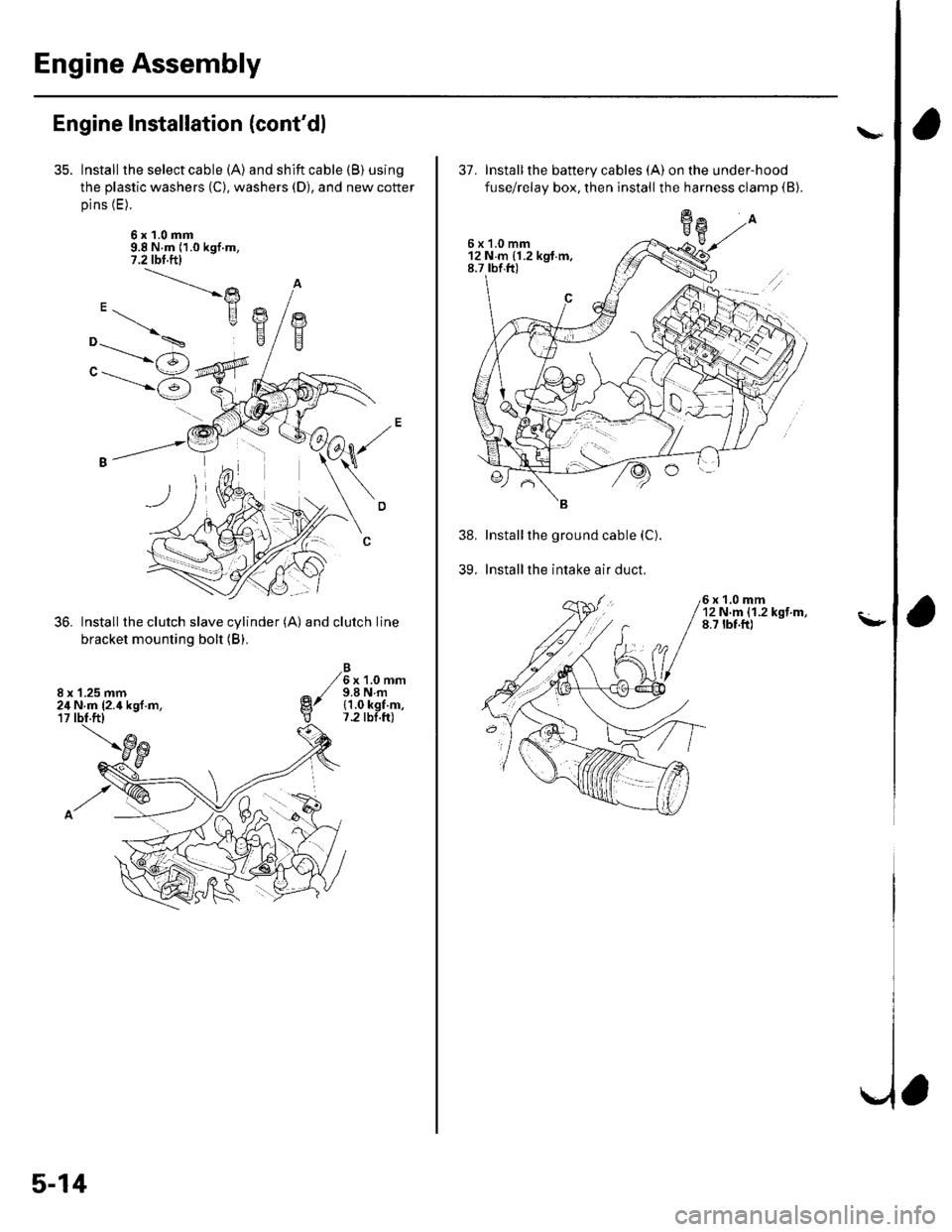
Install the select cable (A) and shift cable (B) using
the plastic washers (C), washers (D), and new cotter
pins (E).
6x1.0mm9.8 N.m (1.0 kgf.m,7.2 tbl.ftl
Install the clutch slave cylinder (A) and clutch line
bracket mounting bolt (B).
6x1.0mm9.8 N.m{1.0 kgf.m,7.2 tbt.ft)
"-.----->)
"------'6
8 x '1.25 mm24 N.m (2.4 kgl.m,
5-14
37. Installthe battery cables (A) on the under-hood
fuse/relay box, then install the harness clamp (B).
Installthe ground cable (C).
Installthe intake air duct.
6x1.0mm12Nm{1.2kgf.m,8.7 tbf.ft)
39.
\"
\-
a
6x1.0mm12Nm{1.2kgt.m,8.7 rbf.ft)
Page 201 of 1139
Fan Controls
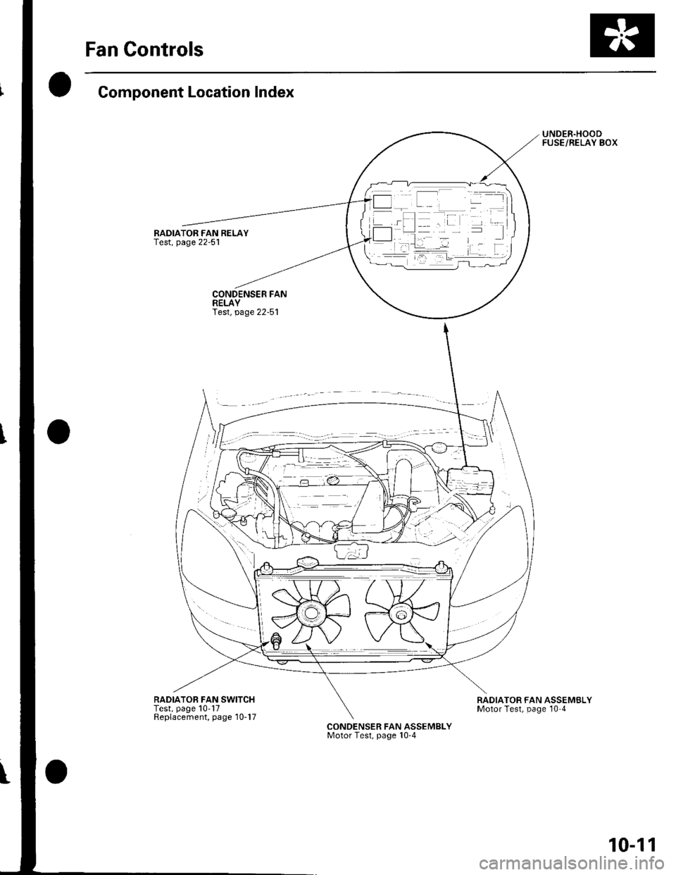
Component Location Index
RADIATOR FAN RELAY
RADIATOB FAN SWITCHTest, page 10'17Replacement, page'10-17
UNDER.HOODFUSE/RELAY BOX
RADIATOR FAN ASSEMBLYMotor Test, page 10 4
CONDENSER FAN ASSEMBLYMotor Test, page 10-4
10-11
Page 203 of 1139
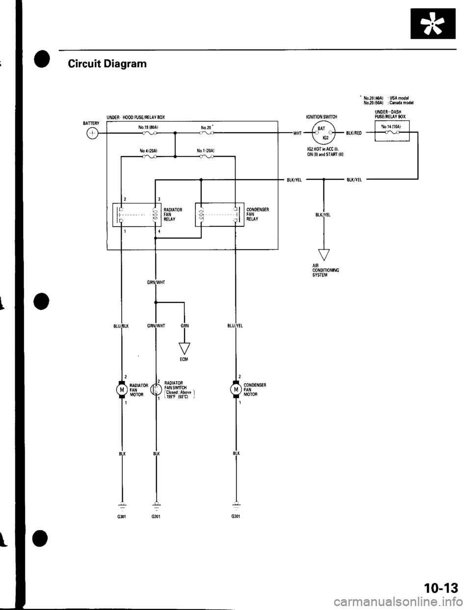
oCircuit Diagram
UIIDEF HOOD FJSE/NILAY BOX
' No.20loA) : USA moddNo.20l50A) : Cm.de mod.l
UNDEN DASXFUSE/RELAY BOX
lG2H0TiiAClill,0N{lllrndSTABI llll)
10-13
Page 204 of 1139
Fan Gontrols
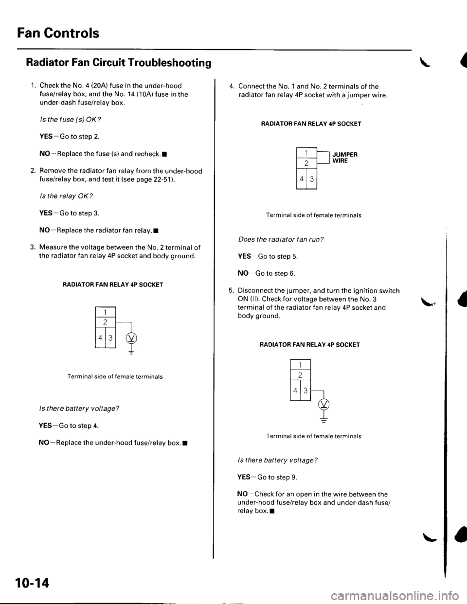
Radiator Fan Circuit Troubleshooting
1. Check the No. 4 (20A) fuse in the under-hood
fuse/relay box, and the No. 14 (10A) fuse in the
under-dash fuse/relay box.
ls the tuse (s) OK?
YES-Go to step 2.
NO- Replace the fuse (s) and recheck.l
2. Remove the radiator fan relay from the under-hood
fuse/relay box, and test it (see page 22-51).
ls the relay OK?
YES Go to step 3.
NO Replace the radiator fan relay. t
3. Measure the voltage between the No. 2 terminal of
the radiator fan relay 4P socket and body ground.
RADIATOR FAN RELAY 4P SOCKET
Terminal side of female terminals
ls there battery voltage?
YES Go to step 4.
NO Replace the under-hood fuse/relay box. I
10-14
\-
(
4. Connect the No. landNo.2terminalsofthe
radiator fan relay 4P socket with a jumper wire.
RADIATOR FAN RELAY 4P SOCKET
JUMPERWIRE
Terminal side of Iemale terminals
Does the radiatot fan run?
YES Go to step 5.
NO Go to step 6.
Disconnect the jumper, and turn the ignition switch
ON { ll}. Check for voltage between the No. 3
terminal of the radiator fan relay 4P socket and
body ground.
BADIATOB FAN RELAY 4P SOCKET
Termlnal side of female terminals
ls there battety voltage?
YES-Go to step 9.
NO Check for an open in the wire between the
under-hood fuse/relay box and under-dash fuse/
relay box.l
\-
Page 205 of 1139
7.
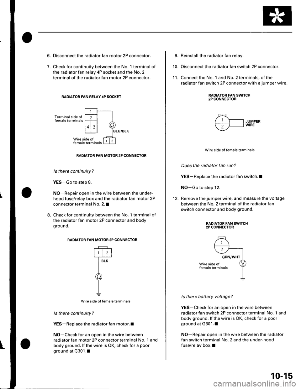
Disconnect the radiator fan motor 2P connector.
Check for continuity between the No. 1 terminal of
the radiator fan relay 4P socket and the No. 2
terminal of the radiator fan motor 2P connector.
RAOIATOR FAN REI-AY 4P SOCKET
Terminal side offemale terminals
RADIATOR FAN MOTOR 2P CONNECTOR
ls thete continuity?
YES-Go to step 8.
NO Repair open in the wire between the under-
hood fuse/relay box and the radiator fan motor 2P
connector terminal No. 2,I
8. Check for continuity between the No, 1terminal of
the radiator fan motor 2P connector and bodv
g rou nd.
RADIATOR F
Wire side of female terminals
ls there continuity?
YES Replace the radiator fan motor.l
NO Check for an open in the wire between
radiator fan motor 2P connector terminal No. 1 and
body ground. lf the wire is OK, check for a poor
ground at G301.1
AN MOTOR 2P CONNECTOR
rftr
T-
Y
9.
10.
Reinstall the radiator fan relay.
Disconnect the radiator fan switch 2P connector.
Connect the No. 1 and No. 2 terminals, of the
radiator fan switch 2P connector with a jumper wire.
RAOIATOR FAN SWITCH2P CONNECTOR
11.
5\- IJUMPERf-; 'fl I wrRE
--
Wire side of female terminals
Does the radiator fan run?
YES- Replace the radiator fan switch.l
NO-Go to step 12.
Remove the jumper wire, and measure the voltage
between the No, 2 terminal of the radiator fan
switch connector and body ground,
RADIATOR FAN SWITCH2P CONNECTOR
ls there battery voltage?
YES Check for an open in the wire between
radiator fan switch 2P connector terminal No. 1 and
body ground. lf the wire is OK, check for a poor
ground at G301.1
NO Repair open in the wire between the radiator
fan switch terminal No. 2 and the under-hood
fuse/relay box.l
10-15
Page 206 of 1139
Fan Controls
Radiator Fan Switch Circuit
Troubleshooting (Openl
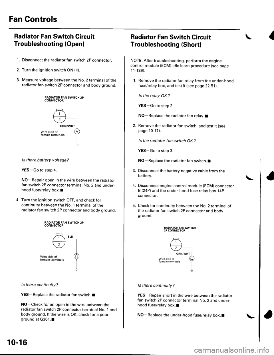
1. Disconnect the radiator fan switch 2P connector.
2. Turn the ignition switch ON (ll).
3. Measure voltage between the No.2 terminal ofthe
radiator fan switch 2P connector and body ground.
RADIATOR FAN SWITCH 2PCONNECTOR
ls there battety voltage?
YES-Go to step 4.
NO- Repair open in the wire between the radiator
fan switch 2P connector terminal No. 2 and under-
hood fuse/relay box.l
Turn the ignition switch OFF, and check for
continuity between the No. '1 terminal of the
radiator fan switch 2P connector and body ground.
RADIATOB FAN SWITCX 2PCONNECTOR
ls there continuity?
YES Replace the radiator fan switch. t
NO Check for an open in the wire between theradiator fan switch 2P connector terminal No. 1 and
body ground. lf the wire is OK, check for a poor
ground at G301.1
10-16
\-
Radiator Fan Switch Circuit
Troubleshooting (Short)
NOTE: After troubleshooting, perform the engine
control module (ECM)idle learn procedure (see page
1 1,139).
1. Remove the radiator fan relay from the under-hood
fuse/relay box, and test it (see page 22-51).
ls the relay OK?
YES Go to step 2.
NO Replace the radiator fan relay.I
2. Remove the radiator fan switch, and test it (see
page 10-17 ).
Is the radiatot tan switch OK?
4.
YES Go to step 3.
NO Replace the radiator fan switch.I
Disconnect the battery negative cable from the
battery.
Disconnect engine control module {ECM) connector
B (24P) and the under hood fuse relay box 14P
connector.
Check for continuity between the No. 2 terminal of
the radiator fan switch 2P connector and bodygrouno.
RADIATOR FAN SWITCH2P CONNECTOR
lstnere continuity?
YES Repair short in the wire between the radiator
fan switch 2P connector terminal No. 2 and under-
hood fuse/relay box.l
NO Replace the under-hood fuse/relay box.t
\I
\
Page 211 of 1139
Fuel and Emissions Systems
General Troubleshooting Information (cont'dl
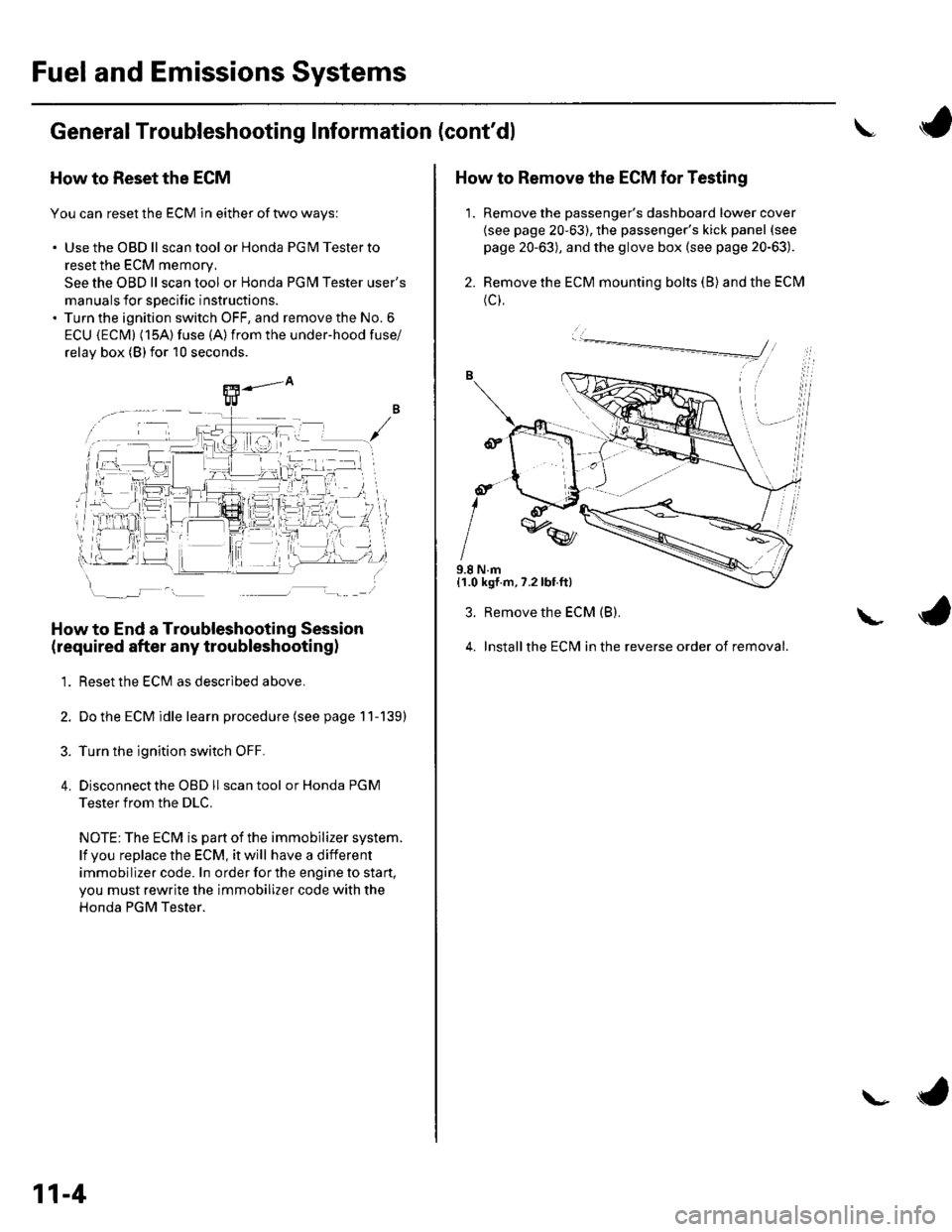
How to Reset the ECM
You can reset the ECM in either of two ways:
. Use the OBD ll scantool or Honda PGMTesterto
reset the ECM memory.
See the OBD ll scan tool or Honda PGI\4 Tester user's
manuals for specific instructions.' Turn the ignition switch OFF, and remove the No. 6
ECU {ECM} (15A) fuse (A)from the under-hood fuse/
relav box (Blfor 10 seconds.
How to End a Troubleshooting Session
(required after any troubleshootingl
1. Reset the ECM as described above.
2. Do the ECM idle learn procedure (see page 11-139)
3. Turn the ignition switch OFF.
4. Disconnectthe OBD ll scan tool or Honda PGM
Tester from the DLC.
NOTE: The ECM is part of the immobilizer system.
lf vou replace the ECM, it will have a different
immobilizer code. In order for the engine to start,
you must rewrite the immobilizer code with the
Honda PGM Tester.
11-4
\- ta
J
How to Remove the ECM for Testing
1. Remove the passenger's dashboard lower cover
{see page 20-63), the passenger's kick panel (see
page 20-63), and the glove box (see page 20-63).
2. Remove the ECM mounting bolts (B) and the ECM
(c),
9.8 N.m{1.0 kgf.m,7.2lbt.ft}
3. Remove the ECM (B).
4. Installthe ECM in the reverse order of removal.
L
Page 222 of 1139
J/-\-1\_/
BEIAY2
A/C CLUTCH RELAY
RAOIATOR
I
)
T
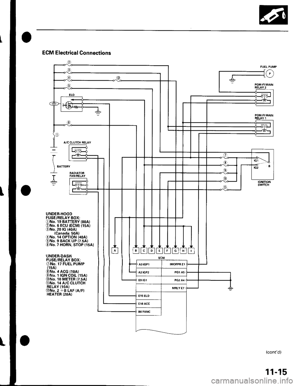
UNDER.HOODFUSE/RELAY BOX:ONo. 19 BATTERY (8oA)ONo. 6 ECU (ECM) (15A1(3)No.20lG {40A1{Canada:50A}ONo. l4 OPTION {40A1€)No. 9 BACK uP (7.5A1lo)No. 7 HORN, STOP {15A}
UNDER.DASHFUSE/RELAY BOX:ONo. 17 FUEL PUMP{15A}@No. ,t ACG {10A)ONo. 1 IGN COIL (1sA)q)No. 10 METER (7.5A)0)No. 14 A/C CLUTCHRELAY IlOA)@No.2 +B LAF (A/F)HEATER (2OA)
(cont'd)
11-15
Page 252 of 1139
""rr"a* JIr''lHr/cnN 1
CONNECTOR E
CONNECTOi K
CONNECTOFJ/GRN
IGNITIONSWITCH
lG2
'I
TESTTACHOMETERCONNECTO8
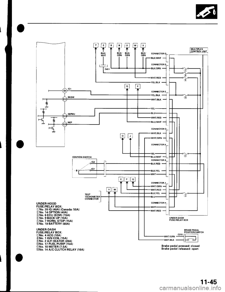
UNDER.HOOD
UNDER.DASHFUSE/RELAY BOX:
UNDER.DASHFUSE/FELAY BOX
Brake pedal pressed: closedBrake pedal releasedr open
POStTtON SWTTCH
,or"-9J3{51re* _{F "_.rl
4 ACG (1oAt1 tGN CO|L t15A)2 A/F HEATER {2OA)17 FUEL PUMP I15A}1O METER {7.5AI14 A/C CLUTCH RELAY {1OA}
11-45