heater troubleshooting HONDA CIVIC 2003 7.G User Guide
[x] Cancel search | Manufacturer: HONDA, Model Year: 2003, Model line: CIVIC, Model: HONDA CIVIC 2003 7.GPages: 1139, PDF Size: 28.19 MB
Page 787 of 1139
Heating and Air Conditioning
DTC Troubleshooting
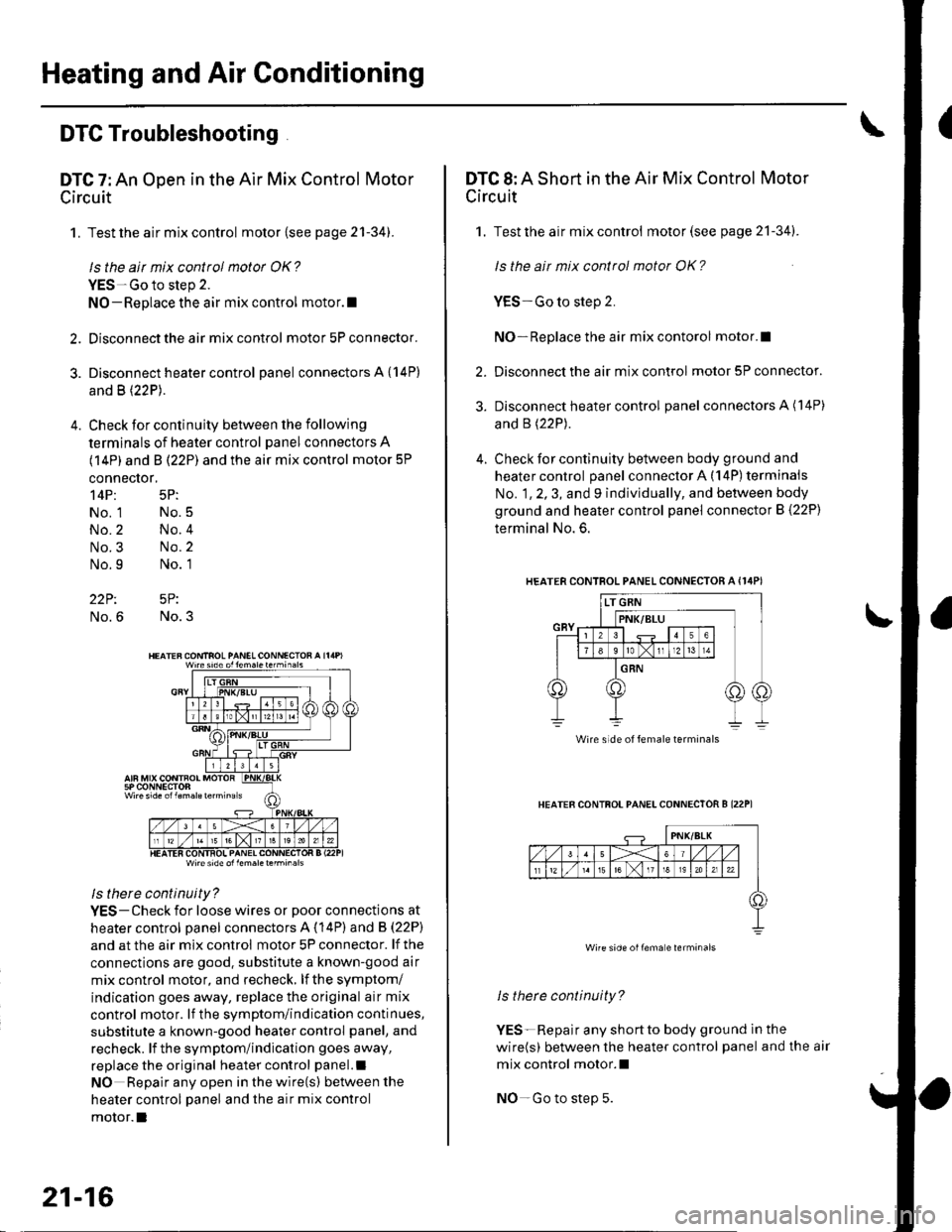
DTC 7: An Open in the Air Mix Control Motor
Circuit
1. Test the air mix control motor {see page 2'l-341.
ls the air mix control motor OK?
YES-Go to step 2.
NO-Replace the air mix control motor.l
2. Disconnect the air mix control motor 5P connector.
3. Disconnect heater control panel connectors A {14P)
and B (22P).
4. Check for continuity between the following
terminals of heater control panel connectors A
(14P) and B (22P) and the air mix control motor 5P
connector,
14P: 5P:
No. 1 No.5
No.2 No.4
No.3 No.2
No.9 No. 1
22P: 5P:
No.6 No.3
Wire side ol lem.letehi.6ls
ls there continuity?
YES-Check for loose wires or poor connections at
heater control oanel connectors A (14P) and B (22P)
and at the air mix control motor 5P connector. lf the
connections are good. substitute a known-good air
mix control motor, and recheck, lf the symptom/
indication goes away, replace the original air mix
control motor. lf the symptom/indication continues,
substitute a known-good heater control panel, and
recheck. lf the symptom/indication goes away,
replace the original heater control panel.l
NO Repair any open inthewire(s) ketweenthe
heater control panel and the air mix control
motor.l
21-16
DTC 8: A Short in the Air Mix Control Motor
Circuit
1. Test the air mix control motor(see page 21-341.
ls the ait mix control motor OK?
YES-Go to step 2.
NO-Replace the air mix contorol motor.I
2. Disconnect the air mix control motor 5P connector.
3. Disconnect heater control panel connectors A (14P)
and B (22P).
4. Check for continuity between body ground and
heater control panel connector A (14P) terminals
No. 1, 2, 3, and 9 individually, and between body
ground and heater control panel connector B (22P)
terminal No. 6.
HEATERCONTROL PANEL CONNECTOR A {I4PI
HEATER CONTFOL PANELCONNECTOR B I22P1
ls therc continuity?
YES-Repair any shortto body ground ln the
wire(s) between the heater control panel and the air
mix control motor.l
NO-Go to step 5.
Wire side of female terminals
Wire side oilema e lerminals
Page 789 of 1139
Heating and Air Conditioning
DTC Troubleshooting.(cont'd)
DTC 10: An Open or Short in the Mode
Control Motor Circuit
1. Test the mode control motor (see page 21-35).
ls the mode cottol motor OK?
YES Go to step 2.
NO Replace the mode control motor.I
Disconnect the mode control motor 10P connector.
Disconnect heater control panel connectors A (14P)
and B \22P1.
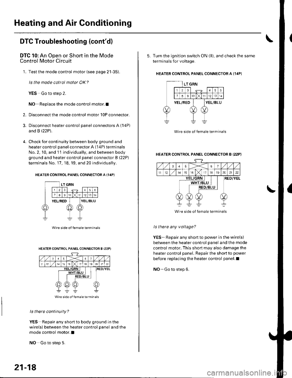
Check for continuity between body ground and
heater control panel connector A (14P) terminals
No. 2, 10, and 11 individually, and between body
ground and heater control panel connector B (22P)
terminals No. '17, 18, 19, and 20 individually.
HEATER CONTROL PANEL CONNECTOR A {14PI
2.
3.
Wire side ol lemale terminals
ls there continuity?
YES Repair any shortto body ground in the
wire(s) between the heater control panel and the
mode control motor.l
NO Go to step 5.
HEATER CONTROL PANELCONNECTOR B {22P)
Wire side of femaLe lerminals
21-18
5. Turn the ignition switch ON (ll), and check the same
terminals for voltage.
HEATEB CONTROL PANEL CONNECTOR A {14P)
Wire side of female terminal
HEATER CONTROL PANEL CONNECTOR B {22PI
35X6
tl1215T61118t92A2122
RED/YELWHT
Wire side of female terminals
ls there any voltage?
YES-. Repair any short to power in the wire(s)
between the heater control panel and the mode
control motor. This short may also damage the
heater control panel. Repair the short to power
before replacing the heater control panel.l
NO- Go to step 6.
Page 795 of 1139
Heating and Air Gonditioning
\
DTC Troubleshooting {cont'd)
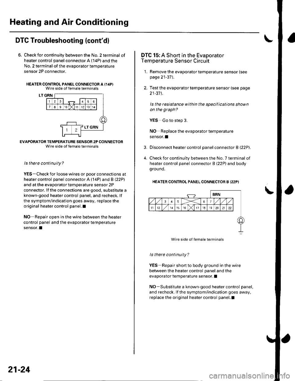
6. Check for continuity between the No. 2 terminal of
heater control panel connector A (14P) and the
No, 2 terminal of the evaporalor temperature
sensor 2P connector.
HEATER CONTROL PANEL CONNECTOR A {14PIWire side of female terminals
LT GRN
EVAFORATOR TEMPERATURE SENSOR 2P CONNECTORWire side of female terminals
ls there continuity?
YES-Check for loose wires or Door connections at
heater control panel connector A ('l4P) and B l22Pl
and at the evaporator temperature sensor 2P
connector. lf the connections are good, substitute a
known-good heater control panel, and recheck. lf
the symptom/indication goes away, replace the
original heater control panel.l
NO Reoair ooen in the wire between the heater
control panel and the evaporator temperature
sensor.I
21-24
4.
DTC 15: A Short in the Evaporator
Temperature Sensor Circuit
1. Remove the evaporator temperature sensor (see
page 21-37).
2. Test the evaporator temperature sensor (see page
21-37 J.
ls the resistance within the specifications shown
on the graph?
YES Go to step 3.
NO Replace the evaporator temperature
sensor. !
Disconnect heater control panel connector B l22Pl.
Check for continuity between the No. 7 terminal of
heater control panel connector B {22P) and body
ground.
HEATER CONTROL PANEL CONNECTOR B (22P)
Wire side of female terminals
ls there continuity?
YES Repair short to body ground in the wire
betvveen the heater control panel and the
evaporator temperature sensor. I
NO-Substitute a known-good heater control panel,
and recheck. lf the symptom/indication goes away,
replace the original heater control panel.I
Page 796 of 1139
3.
Recirculation Control Motor Circuit Troubleshooting
1. Check the No. 14('10A)fuse inthe under-dashfuse/
relay box.
ls the f use OK?
YES Go to step 2.
NO- Replace the fuse, and recheck.l
2. Disconnect the recirculation control motor 5P
conneclor.
Turn the ignition switch ON (ll).
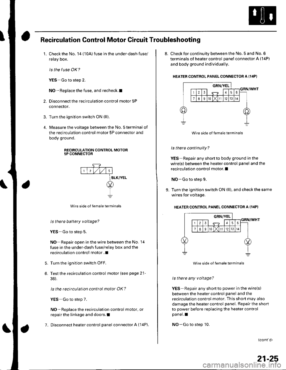
lvleasure the voltage between the No. 5 terminal of
the recirculation control motor 5P connector and
body ground.
RECIRCULATION CONTROL MOTOR5P CONNECTOR
7.
Wire side of female terminals
ls there battery voltage?
YES Go to step 5.
NO- Repair open in the wire between the No. 14
fuse in the under-dash fuse/relay box and the
recirculation control motor .l
Turn the ignition switch OFF.
Testthe recirculation control motor {see page 21-
36),
ls the recirculation control motor OK?
YES Go to step 7.
NO- Replace the recirculation control motor, or
repair the linkage and doors.I
Disconnect heater control panel connector A (14P).
5.
6.
8. Check for continuity between the No. 5 and No. 6
terminals of heater control panel connector A (14P)
and body ground individually.
HEATER CONTROL PANEL CONNECTOR A I14P)
Wire side of female terminals
ls there continuity?
YES Repair any shortto body ground in the
wire(s) between the heater control panel and the
recirculation control motor.l
NO-Go to step 9.
9. Turn the ignition switch ON (ll), and check the same
wires for voltage.
HEATER CONTROL PANEL CONNECTOR A Il4PI
Wire side of lemale terminals
ls therc any voltage?
YES Repair any shonto power in the wire(s)
between the heater control panel and the
recirculation control motor. This shon may also
damage the heater control panel. Repair the shon
to power before replacing the heater control
pa nel. I
NO-Go to step 10.
{cont d r
21-25
Page 797 of 1139
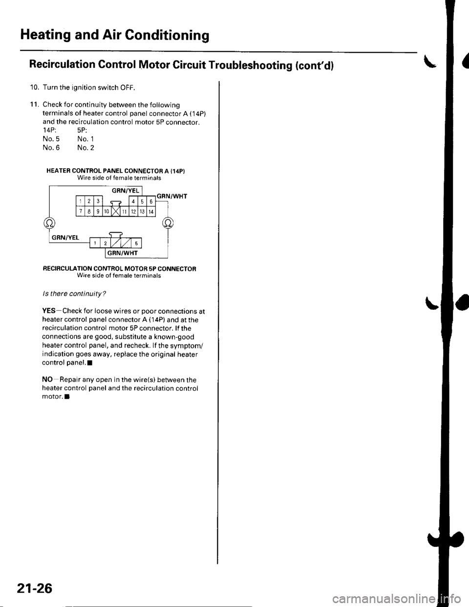
Heating and Air Conditioning
Recirculation Control Motor Circuit Troubleshooting (cont'd!
10. Turn the ignition swirch OFF.
11. Check for continuity between the following
terminals of heater control panel connector A ( 14P)
and the recirculation control motor 5P connector.'l4Pt 5P:
No.5 No. 1
No.6 No.2
HEATER CONTROL PANEL CONNECTOR A {14P}Wire side ol temale terminats
RECIRCULATION CONTROL MOTOR 5P CONNECTORWire side ol lemale terminals
ls there continuity?
YES Check for loose wires or poor connections at
heater control panel connector A ( 14P) and at the
recirculation control motor 5P conneclor. lf the
connections are good, substitute a known-good
heater control panel, and recheck. lf the symptom/
indication goes away, replace the original heater
control panel,I
NO Repair any open in the wire{s) between the
heater control panel and the recirculation control
motor.l
21-26
Page 798 of 1139
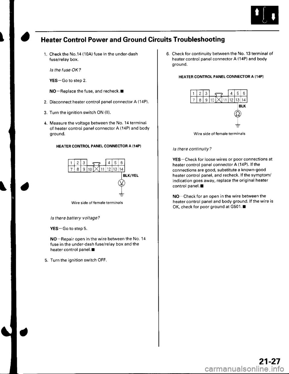
Heater Control Power and Ground Circuits Troubleshooting
1. Check the No.14 (10A)fuse in the under-dash
fuse/relay box.
ls the f use OK?
YES-Go to step 2.
NO-Replace the fuse, and recheck.l
2. Disconnect heater control panel connectorA{'14P).
3. Turn the ignition switch oN (ll).
4. Measure the voltage between the No. l4terminal
of heater control panel connector A (14P) and body
grouno.
HEATER CONTROL PANEL CONNECTOR A {14P}
23456
78I10 l,111214
Wire side of temale terminals
BLK/YEL
ls there battery voltage?
YES-Go to step 5.
NO Repair open in the wire betvveen the No. 14
fuse in the under-dash fuse/relay box and the
heater control panel.l
Turn the ignition switch OFF.
6. Check for continuity between the No. l3terminal of
heater control panel connector A (14P) and body
g rou nd.
HEATER CONTRoL PANEL CONNEcToR A (1ilP)
123456
I89r0 t,1l1214
BLK
.o
Wire side of temaleterminals
ls therc continuity?
YES Check for loose wires or poor connections at
healer control panel connector A (14P). lfthe
connections are good, substitute a known-good
heater control panel, and recheck. lf the symptom/
indication goes away, replace the original heater
control panel.l
NO Check for an open in the wire between the
heater control panel and body ground. lf the wire is
OK, check for poor ground at G501. I
21-27
Page 803 of 1139
Heating and Air Conditioning
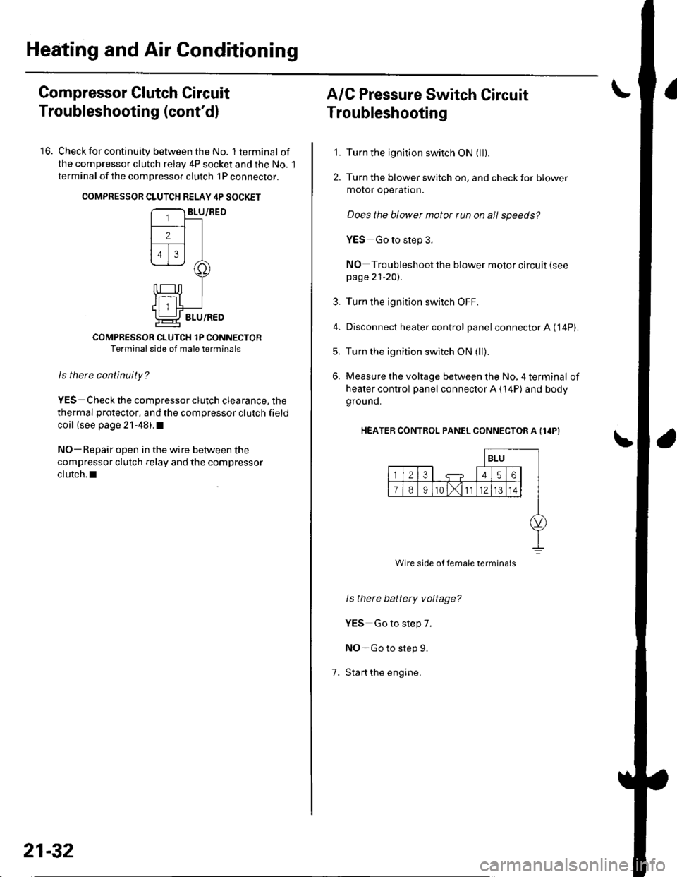
Compressor Clutch Circuit
Troubleshooting (cont'dl
16. Check for continuity between the No. lterminal of
the compressor clutch relav 4P socket and the No. l
terminal of the compressor clutch 1P conneclor.
COMPRESSON CLUTCH RELAY 4P SOCKET
COMPRESSOR CLUTCH 1P CONNECTORTerminal side of male terminals
ls therc continuity?
YES-Check the compressor clutch clearance, the
thermal protector, and the compressor clutch field
coil (see page 21-48).I
NO-Repair open in the wire between the
compressor clutch relay and the compressor
clutch.l
21-32
A/C Pressure Switch Circuit
Troubleshooting
'1. Turn the ignition switch ON {ll).
2. Turn the blower switch on, and check for blower
motor operatron.
Does the blower motor run on all speeds?
YES Go to step 3.
NO Troubleshoot the blower motor circuit (see
page 21-20).
3. Turn the ignition switch OFF.
4. Disconnect heater control panel connectorA ('14P).
5. Turn the ignition switch ON (ll).
6. Measure the voltage between the No, 4 terminal of
heater control panel connector A {14P) and body
grou nd.
HEATER CONTROL PANEL CONNECTOR A (I4P}
1.
ls there battety voltage?
YES Go to step 7.
NO-Go to step 9.
Stan the engine.
Wire side of female termina's
Page 804 of 1139
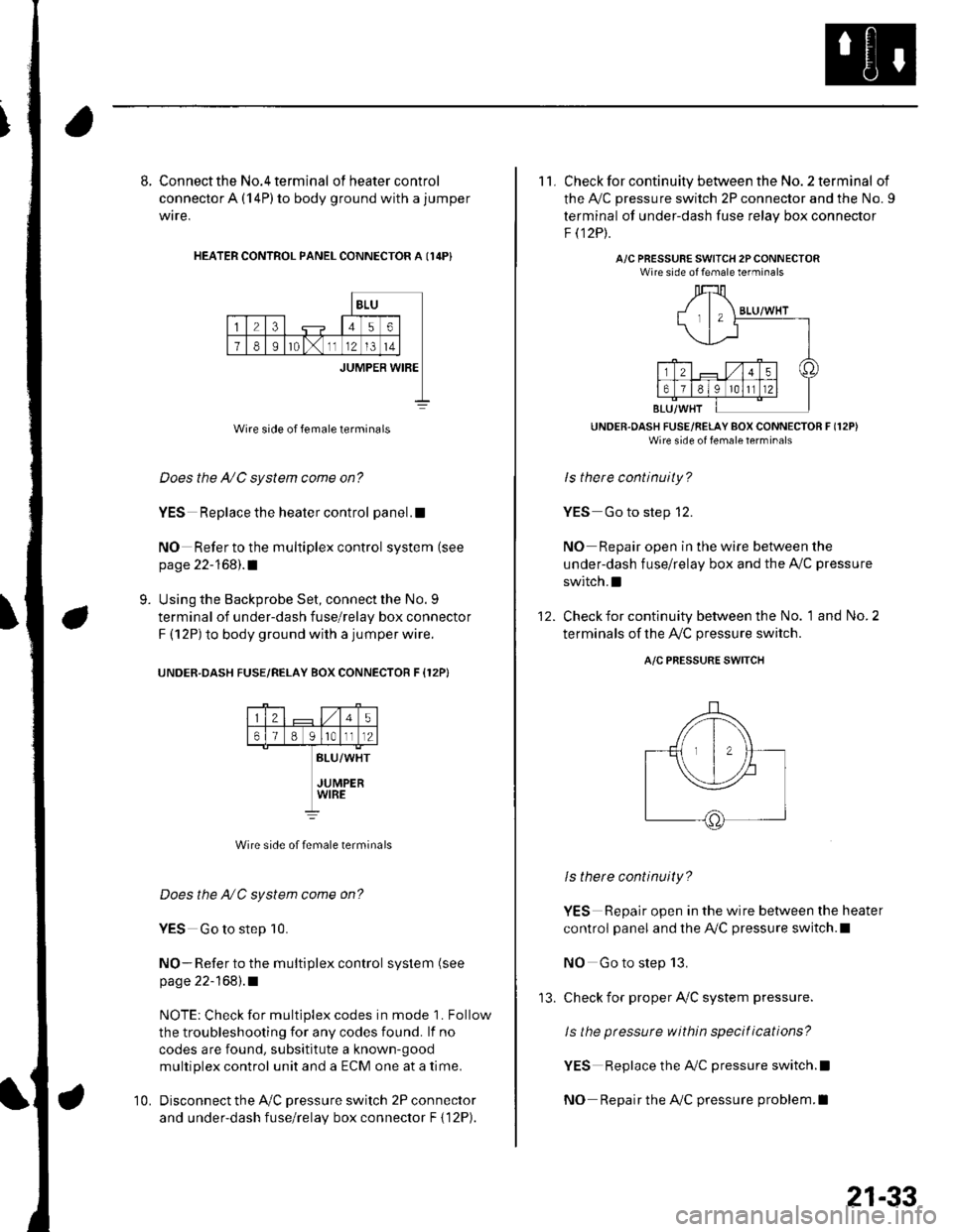
8. Connect the No.4 terminal ofheatercontrol
connector A (14P) to body ground with a jumper
wire,
HEATER CONTROL PANEL CONNECTOR A I14P}
BLU
23456
78Ir0lx1112l3t4
JUMPER WIBE
Wire side of female terminals
Does the A/C system come on?
YES Replace the heater control panel.!
NO Refer to the multiplex control system (see
page 22-168).1
Using the Backprobe Set, connect the No. 9
terminal of under-dash fuse/relay box connector
F (12P) to body ground with a jumper wire.
UNOER.DASH FUSE/RELAY BOX CONNECTOR F {12P}
9.
25
61B g lrotll2
BLU/WHT
JUMPERWIRE
Wire side of female terminals
Does the NC system come on?
YES Go to step 10.
NO- Refer to the multiplex control system (see
page 22-168).1
NOTE: Check for multiplex codes in mode '1. Follow
the troubleshooting {or any codes found. lf no
codes are found, subsititute a known-9ood
multiplex control unit and a ECM one at a time.
Disconnect the Ay'C pressure switch 2P connector
and under-dash fuse/relay box connector F { 12P).
10.
'13.
21-33
11. Check for continuity between the No. 2 terminal of
the A,/C pressure switch 2P connector and the No. 9
terminal of under-dash fuse relav box connector
F t12Pt.
A/C PRESSURE SWITCH 2PCONNECTORWire side of female terminals
UNDER.OASH FUSE/RELAY BOX CONNECTOR F (12P)
Wire side of fenale lerrrinal'
ls there continuity?
YES Go to step 12.
NO Repair open in the wire between the
under-dash fuse/relay box and the A,,/C pressure
switch.I
Check for continuity between the No. 1 and No. 2
terminals of the A,/C pressure switch.
12.
A/C PRESSURE SWITCH
ls there continuity?
YES Repair open in the wire between the heater
control panel and the A,/C pressure switch.l
NO Go to step 13.
check for proper Ay'C system pressure.
ls the pressure within specitications?
YES Replace the AilC pressure switch.l
NO Repair the AilC pressure problem.I
Page 1135 of 1139
)
Orive BehInspecaron................ 4-26
Door PanelsRemoval/lnstallation -............................. 20-4
Door Sash TrimRep1acement......................................... 20 10
Door StrikersAdiustment ........................................... 20-13
Door Weatherst psBeplacement...........-............................. 20 1 1
EPS Conirol UnitRemoval/1nsta11ation ..................-......... 17-67
EPS Indicator CircuitTroubleshooting ................................... 17 -47
EPS MotorRemoval/lnstallation .-.......................... 17-49
EVAP CanisterRep1acement......................... ......... 11,189
EVAP Control Syst€mComponentLocation Index ..............'11-170
EVAP Two-Wey ValveTest ..........-.............-............................ 11 186
Evaporetor CoreRep1acement........................ . ... 21-42
Evaporator Tomperature SensorReplacement......................................... 21 -37Test..................................... ..........2137
EvaporrtoFHeater UnitReplacement........................................ 21 43
Exhaust ManifoldRemoval/1nsta11ation ................................ I 7
Exhaust Pipe8ep|acement............................................. 9-8
Front SpeakersRep|acement....................................... 22-102
Front SuspensionComponentLocation Index................... 18-3
Fueland EmissionsDescription ........................................... 11-12
Fuel Fill DoorAdjustment ..........-................................ 20 93
Fuel Fill Door OpenetBeplacement........................ . ............ 20.109
Fuel Fill Door Opener CableReplacement....................................... 20- lO7
Fuel FilterReplacement....................................... 1 1-152
Fuel Gauge Sending UnitTest ......................-.-..........-.................. 11'156
Fuel Injection Syslem (PGM"FIlComponent Location 1ndex................. 11-49
Fuel IniectorsRep1acemen1....................................... 1 1 1 1 l
Fuel Lines and HosesInspection .......................................... 1 1'146Removal ....................... . .. . .... 11-149Insta|1ation .......................................... 1 1 150
FuelPipe ProtectolReplacement....................................... 20-104
Fuel Pressure RegulatotReplacement....................................... 1 1-152
Fuel Pulsation DamperReplacemenl................................... 11 154
Fuel PumpReplacement,,,,,.,.,.,,,.,,,,,,,,,,,,.,.,.,,,..,.. 11-153
Fuel Pump CircuitTroubleshooting -.......-....................... 1 1-141
FuelSupply SystemComponent Location lndex .............. 11 140Adjustment................................... 11-144Test........-...-................. ... ............- 11-145
FuelTankBeplacemenl.............. . ..... .. 11 155
Fuel Tank Vapor ControlValveTest ......................-....... ... . . 11-187Replacement,,.,,...,.,,,.,.,,,,... .. .. 11 189
Fuses{See first page ofthis Index)
)
Rep|acement................. ..................... 4 26
Drive Belt Auto-tensionellnspection ............................................... 4 21Rep1acement.................................... ..4-28
Driver's PocketRemoval/lnstallation -........................... 20-60
Driver's TrayRemoval/lnstallation .........................-.- 20-65
DRL {Daytime Running LightslControl Unitlnput Test .................... ........ . . . ......22-16
DTCs(See first page olthis Index)
Dust and Pollen FillerReplacement......................................... 21-39
Dynamic Damper, DriveshaftsReplacement........................................... 16-8
ECT SensorReplacement.,.,,,.,.,,,,,,,,,,,,,,................ 1 1-1 14
El€ctrical Power Steering IEPS)Signal CircuitTroubleshooting ........ ... .. 11-135
EmblemsReplacement......................-................ 20-100
Engine AssemblyRemova1 .................................................... 5 2Installation ............._.................................. 5-9
Engine Block AssemblyComponent Location Inder ..................... 7.3
Engine Block, BareInspect|onRepair
Fan ControlsComponent Location Index................. 10'l 1Circuit Diagram .. ..... . .. . .................. 10 13
Fender Fairing, FrontReplacement...-................................... 20-103
Final Driven Gear. M/TReplacement.... . . ................................ 13-53
FrameRepair Chan............ ... ....................... 20 11 4
Frame StiffenelReplacement......-................................ 20- J'13
Front ConsoleRemoval/lnstallation ............................ 20 5lDisassembJy/Reassemb|y ................... 20 58
Front DoorsComponent Location Index................... 20-2Adiustment ........................................... 20.12
Front Driveshaft AssemblyInspeclion .................... ... ....16 3Remova1...................-...... ... .....16-3Disassembly ............................... .....165Resassemb|y ................................-......... 16-9Insta11arion ........................ ...... ............ l6 17
Front lmpact SensorsRep1acement............................ ...23 125
................7-15................1 11
)
Entry Light Control SystemComponent Location Index ...............-. 22-89Circuit Dia9ram .................................... 22 90
EPS ComponentsComponent Location 1ndex..........-...... 17-!7Description ........................ ...... ..17-24Circuit Diagram11 26(cont'd)
Page 1136 of 1139
Service Manual Index
(cont'dl
Gauge A3semblyReplacement......................................... 22 64
Gaug€sComponent Location Index ..........-...... 22 54How-to lnformation ........................22-56Circuit Diagram22-54
Heater Valve CableAdjustment ...................... .................... ?1-46
High Mount Brake Light8ep|acement......................................... 22 82
Hood
lmmobilizer SystemComponent Location In dex .............. 22-162
\
G
Description
Genoral Information(See seclion 1)
Glove BoxRemoval/1nsta11ation .......................-.... 20-63
GrilleReplacement...........-............................. 20-94
Hood lnsulatorReplacement......................................... 20-89
Hood LatchRep1acement................... ..........20 108
Hood Opener CableComponentLocation Index ..............20 105Replacement ................ . . ........... .....20 106
Hood SealBeplacement.-...........................-........... 20-88
HornTesVReplacement . . ................ ...... 22-122
CircuitDiagram ...........................22-164Troubleshooting ............................ 22,165
Inner Fender, FronlRepf acemenl....................................... 20-102
Inside Rearview MirrorReplacement..........-.............................. 20 16
Instrument PanelRemoval/1nsta11ation................. ....... 20-59
Intake Air Bypass ControlThermal ValveTesr................................ ..... ..11-161
Intake Air SystemComponent Location Index ...-.-........ 11-159
Intake ManitoldRemoval/1nsta11ation ................................ I 2
lntermediate Shaft AssemblyRemova1 ................-.-...-......................... 16-19Disassemb|y................... ... ......-.... 16,20Resassemb|y ........................................ 16 22Installation .........-...-.............................. 16-24
Keyless Entry Transmitter
Adjuslment
H
Adiustment .......
Hatch Handle
Horn SwitchTest ............-........
HornsComponent Location IndexCirc!it Diagram
H02S. SecondaryReplacement
..............22-120Replacement
22-122
22 12120-110
20-'110Hatch LatchReplacement$
K
Hatch Latch Switch
.... 11 113
HubsReplacement. ... .................................. 1A 26Test
Test
Replacement
Hatch Support StrutsBeplacement.....
Hatch WeatherstrioReplacement....
Hazard Warning Switchtest
ldle ControlSystemComponentLocation Index .............. 11-129Inspection,.,.........-.......,.,.,,,,,,.,,,.,.,..... 1'l 138
lgnition CoillslBemoval/lnstallation ...............-.............. 4 18
22-161Test ...................................................... 22 161
Keyless Entry/Security Alarm SystemComponenl Location Index .............. 22 150Circuil Diagram ................. . .............. 22 151
Keyless Receiver Unitlnput Test ............................................ 22-153
Knock SensorReplacement......-................................ 1 1 115
KnucklesReplacementFront Suspensron ............................. 18-1 1Rear Suspension ........ .................-... 18-28
Repair ...............
H.tch Lock Actuator22-159
Hatch Lock CylinderRep|acement....................................... 20,111
Hatch SpoilerIAT {lntake Air Temperature} SensorReplacement.,.........-...'11 115
20-91
20-92
.................... 22_88lgnition Key LightTest,,.,,,,.,...,......-.
H6adlightAdjustmentlgnition Key Switch
....................... 22-91
....................... 22-91..22-78TestReQ\ace$entlgnition SwitchTest .,,,.,.,.,,,,.,.,.......22-53License Plate LightReplacement...........-... - ... .....22-83
License TrimReplacement..................-...-..........-....... 20-98
Lights, ExteriorComponent Localion Index.................22 68
Lights,InteriorComponent Location Index................. 22-94CircuitDiagram .. .. ...... .... 22-95
HcadlightsCircuit Diagram .............................. 22-71, 72
HeadlinerRemoval/lnstallalion ............................ 20-54
Heater ControlPanelRemoval/1nsta11ation ............................ 21-38
Heater Control Power and Ground CircuitsTroubfeshooting......... .......................21-27
lgnition SystemComponent Location Index ................... 4-15CircuitDia9ram .................................... 4'161nspection ............................................... 4-17
lmmobilizer Control Unit-Receiver
J
22-161