key HONDA CIVIC 2003 7.G User Guide
[x] Cancel search | Manufacturer: HONDA, Model Year: 2003, Model line: CIVIC, Model: HONDA CIVIC 2003 7.GPages: 1139, PDF Size: 28.19 MB
Page 878 of 1139
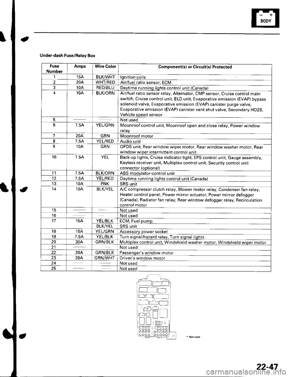
Under-dash Fuse/Relay Box
Fuse
Number
AmpsWire ColorComponent(s) or Circuit(s) Protected
115ABLKA/VHTlgnition coils
2204WHT/REDAirlfuel ratio sensor, ECM
310ARED/BLUDaytime running Iights control unit {Canada)10ABLI(ORNAir/fuel ratio sensor relay, Alternator, CMP sensor, Cruise control main
switch, Cruise control unit. ELD unit, Evaporative emission (EVAP) bypass
solenoid valve, Evaporative emission (EVAP)canister purge valve,
Evaporative emission (EVAP) canister vent shut valve, Secondary H02S,
Vehicle speed sensor
5Not used
67.5AYEUGRNMoonroof control unit, Moonroof open and close relay, Power window
relaV
7204GRNMoonroof motor
I7.5AYEUREDAudio unit
910AGRNOPDS unit, Rear window wiper motor, Rear window washer motor, Rear
window wiper intermittent control unit
107.54YELBack-up lights, Cruise indicator light, EPS control unit, Gauge assembly,
Keyless receiver unit, Multiplex control unit, Security control unit
connector (optional)
117.5ABLIVORNABS modulator-control unit
127.5AYEUREDDaytime runnino liohts control unit (Canada)
1310APNKSRS unit't410ABLK/YE LA,,/C compressor clutch relay, Blower motor relay, Condenser fan relay,
Heater control panel, Power mirror actuator, Power mirror defogger(Canada), Radiator fan relay, Rear window defogger relay, Recirculation
control motor1ENot used
loNot used
1715AYE L/B LKECM, Fuel pump
B LK/YE L>H> Unrr
1815AYEUGRNAccessory power socket
197.5AYEUBLKTurn siqnal/hazard relav, Turn siqnal liohts
2030AGRN/BLKMultiplex control unit, Windshield washer motor. Windshield wioer motor21Not used
22204GRN/BLKPassenqer's window motor
2320A.G R N,A/VHTDriver's window motor
24Not used
25Not used
__^:Hr tl_l
f at-t
at I
r^,rl fl
!!;r -
!339,i;s!!sf Fnf : |rnITf
22-47
Page 879 of 1139
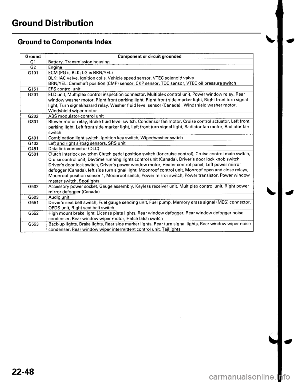
Ground Distribution
Ground to Components Index
GroundComponent or circuit qrounded
Batterv, Transmission housinq
E ngine
G 101ECM (PG is BLK; LG is BRN/YEL)
BLK: IAC valve, lgnition coils, Vehicle speed sensor, VTEC solenoid valve
BRNA/EL: Camshaft oosition (CMP) sensor. CKP sensor, TDC sensor. VTEC oil pressure switch
G 15'�]EPS control unit
G201ELD unit. Multiplex control inspection connector, Multiplex control unit, Power window relay, Rear
window washer motor, Right front parking light, Right front side marker light, Right front turn signal
light, Turn signal/hazard relay, Washer fluid level sensor (Canada) , Windshield washer motor,
Windshield wiDer motor
G202ABS modulator-control unit
G301
G401
Blower motor relay, Brake fluid level switch, Condensor fan motor, Cruise control actuator, Left front
parking light, Left front side marker light, Left front turn signal light, Radiator fan motor, Radiator fan
swrtcn
Combination liqht switch, lqnitlon kev srvitch, Wiper/wasfrer sr,virch
G402Left and riqht airbaq sensors, SRS unit
G 451Data link connector (DLC)
G501Clutch interlock switchm Clutch pedal position switch (for cruise control), Cruise control main switch,
Cruise control unit, Daytime running lights control unit (Canada), Driver's door lock knob switch,
Driver's door lock switch, Driver's power window motor, Heater control panel, Left power mirror
defogger (Canada), left side turn signal light, Moonroof control unit, Monroof open and close relays,
Moonroof position sensor '1, Moonroof seitch, Power mirror switch, Power transistor, Power window
master switch. SDotliqhts
G502Accessory power socket, Gauge assembly, Keyless receiver unit, lvlultiplex control unit, Right power
mirror defogger {Canada)
G503Audio unit
G551Driver's seat belt switch, Fuel gauge sending unit, Fuel pump, Memory erase signal (IMES) connector,
OPDS unit. Rioht seat belt switch
G552High mount brake light, License plate lights, Rear window defogger, Rear window defogger noise
condenser. Rear window wioer motor, Hatch latch switch
Back-up lights, Brake lights, Rear side marker lights, Rear turn signal lights, Rear window wiper noise
condenser, Rear window wiper intermittent control unit, Taillights
22-48
Page 920 of 1139
Entry Light Control System
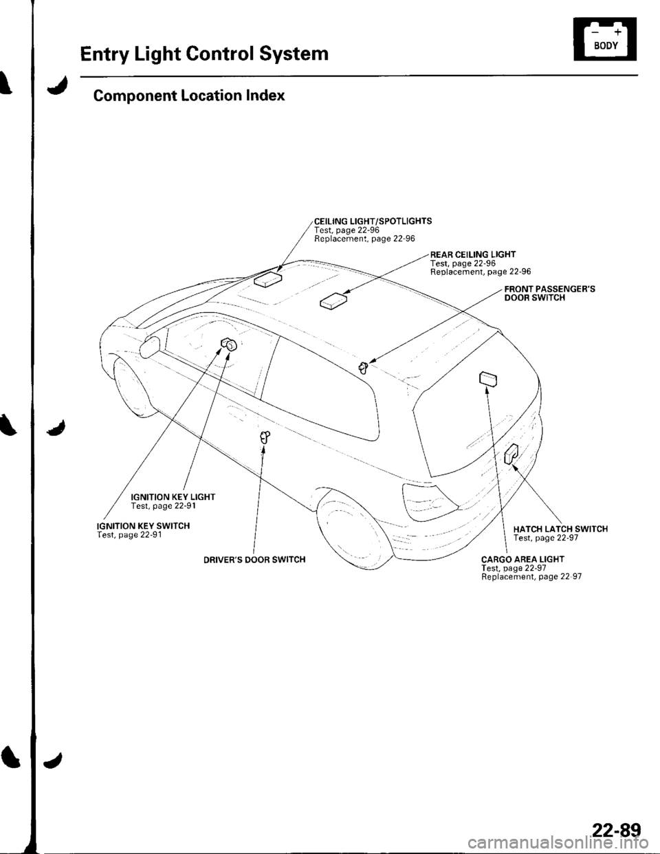
Component Location Index
IGNITION KEY LIGHTTest, page 22-91
IGNITION KEY SWITCHlest, page 22-91
DRIVER'S DOOR SWITCH
CEILING LIGHT/SPOTLIGHTSTest, page 22-96Replacement, page 22-96
REAR CEILING LIGHTTest, page 22-96Replacement, page 22-96
FRONT PASSENGER'SDOOR SWITCH
HATCH LATCH SWITCHTest, page 22-97
CARGO AREA LIGHTTest, page 22-97Replacement, page 22 97
22-89
Page 921 of 1139
Entry Light Control System
Jt
'No.20({0A) USA
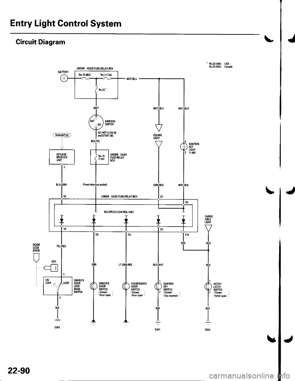
Circuit Diagram
CEILINGUGHT
Y
I
I
J\
jIGNIlx)NKEYSWtTCH
PASSTNGERSDOOBSWITCHi9r"..d l
ORIVEBSDOORSWITCH
DtrVTN'SDOORLocx(NOBs!t/tTc8
l'BU
I
G()t
lGl HoTin 0N illlnd STAnT 0D
EiIIpNSMTqI
UiIOTf, HOOD fUSE/8ELAY BOX
J
22-90
Page 922 of 1139
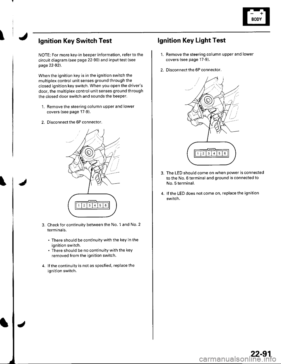
\lgnition Key Switch Test
NOTE: For more key-in beeper information, refer to the
circuit diagram (see page 22-90) and input test (see
page 22-921.
When the ignition key is in the ignition switch the
multiplex control unit senses ground through the
closed ignition key switch. When you open the driver's
door, the multiplex control unit senses ground through
the closed door switch and sounds the beeper.
1. Remove the steering column upper and lower
covers (see page'17-9).
2. Disconnect the 6P connector.
3.Check for continuity between the No. 1 and No. 2
termrnars.
. There should be continuity with the key in the
ignition switch.. There should be no continuity with the key
removed from the ignition switch.
lf the continuity is not as specfied, replace the
ignition switch.
lgnition Key Light Test
1.Remove the steering column upper and lower
covers (see page 17-9).
Disconnect the 6P connector,
The LED should come on when power is connected
to the No. 6 terminal and ground is connected to
No. 5 terminal.
lf the LED does not come on, replace the ignition
swrtch.
i'
/.'
22-91
Page 924 of 1139
I
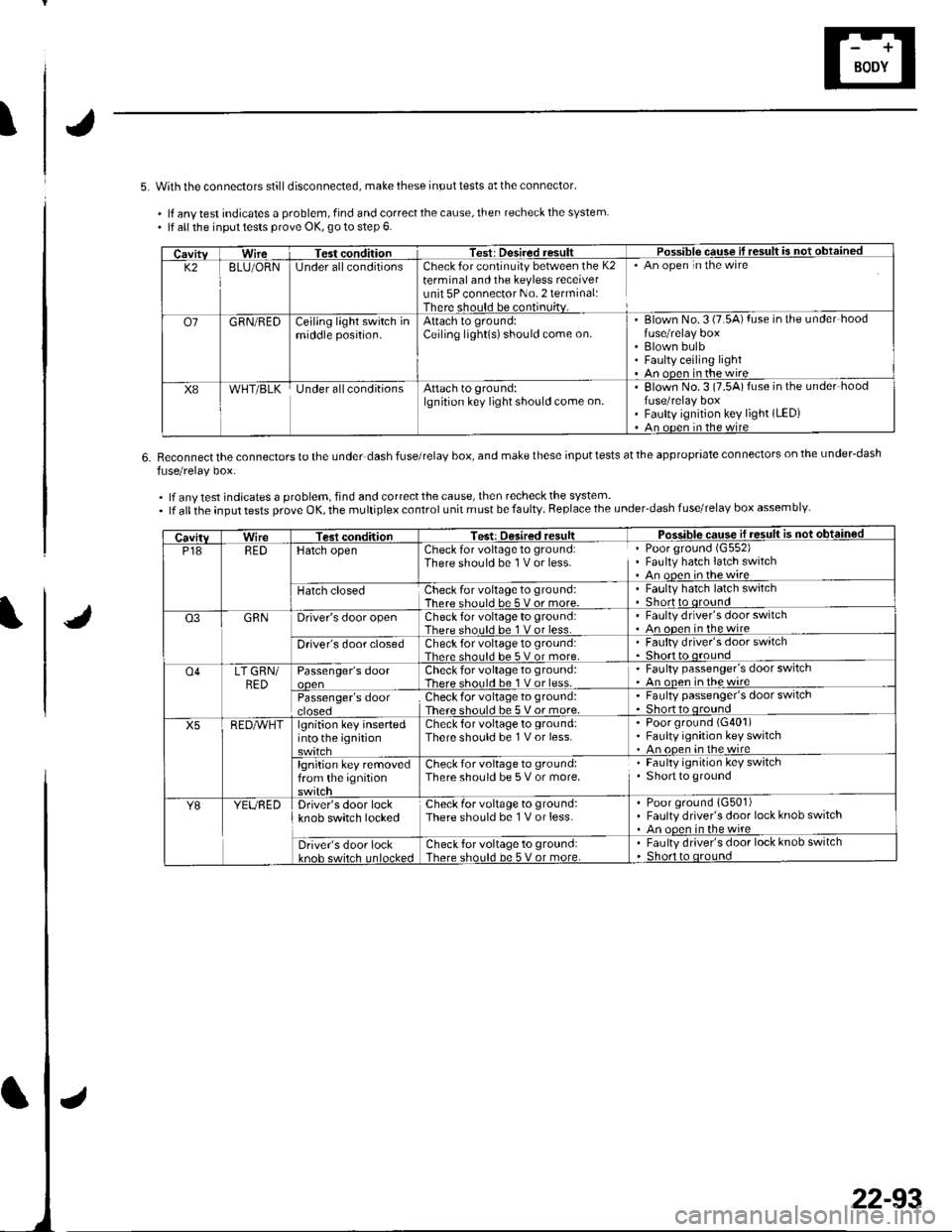
5. With the connectors stilldisconnected, make these input tests at the connector'
. lf anv test indicates a problem, find and correct the cause, then recheck the system. lf all the inpul tests prove OK, go to step 6.
6.Reconnect the connectors to the under dash fuse/relaV box, and make these input tests at the appropriate connectors on the under-dash
fuse/relay box.
.lfanytestindicatesaproblem,findandcorrectthecause,thenrecheckthesystem..lfalltheinputtestsproveOK,themultiplexcontrolunitmustbefaulty.Replacetheunder'dashfuse/relaYboxassemblY
CavitvWireTest conditionTest: Desired resultPossible cquse il result is not obtained
K28LU/ORNlJnder allconditionsCheck for continuity between the K2terminal and the keyless receiverunit 5P connector No. 2 terminal:There should be continuitv.
An open in the wire
o7GRN/REDCejling light switch inmiddle position.Attach to ground:Ceiling light(s)should come on.Blown No. 3 (7.5A) fuse in the under hood
Blown bulbFaulty ceiling lightAn ooen in the wire
X8WHT/BLKUnder allconditionsAttach to ground:lgnition key light should come on.Elown No.3 (7.5A)fuse in the under hoodfuse/relay boxFaulty ignition key light (LED)
An ooen in the wire
CavitvWireTest conditionTest: Desired resultPosq!!!c sq!!ej1!.9!!!!j €d
P18REDHatch openCheck for voltage to ground:There should be 1 V or less.Poor ground (G552)
Fauhy hatch latch switchAn open inthewire
Hatch closedCheck for voltage to ground:There should be 5 v or more.Faulty hatch latch switchShortto oround
Q3GRNDriver's door openCheck for voltage to ground:There should be 1 V or less.Faulty drlver's door switchAn oDen in the wire
Driver's door closedCheck for voltage to ground:Thar. shoul.l he 5 V or more.Faulty driver's door switch
o4LT GRN/BED
RED^vHT
Passenger's doorCheck for voltage to ground:There should be 1 V or less.
' Faulty passenger's door switch' An onen inthewire
Passenger's doorcroseoCheckfor voltage to ground:There should be 5 Vor more.
. Faulty passenger's door switch. Shor o oround
X5lgnition key insertedinto the ignitionCheck for voltage to ground:There should be 1 V or less.Poor ground (G401)
Faulty ignition key switchAn ooen in the wire
lgnition key removedfrom the ignitionCheck for voltage to ground:There should be 5 V or more.Faulty ignition key switchShort to ground
Y8YEUREDDriver's door lockknob switch lockedCheck for voltage to ground:There should be 1 V or less.Poor ground {G501)Faulty driver's door lock knob switchAn ooen in the wire
Driver's door lockkn6h cwirch Inl6cke.lCheck for voltage to ground:There should be 5 V or more.Faulty driver's door lock knob switchShort to oround
22-93
Page 981 of 1139
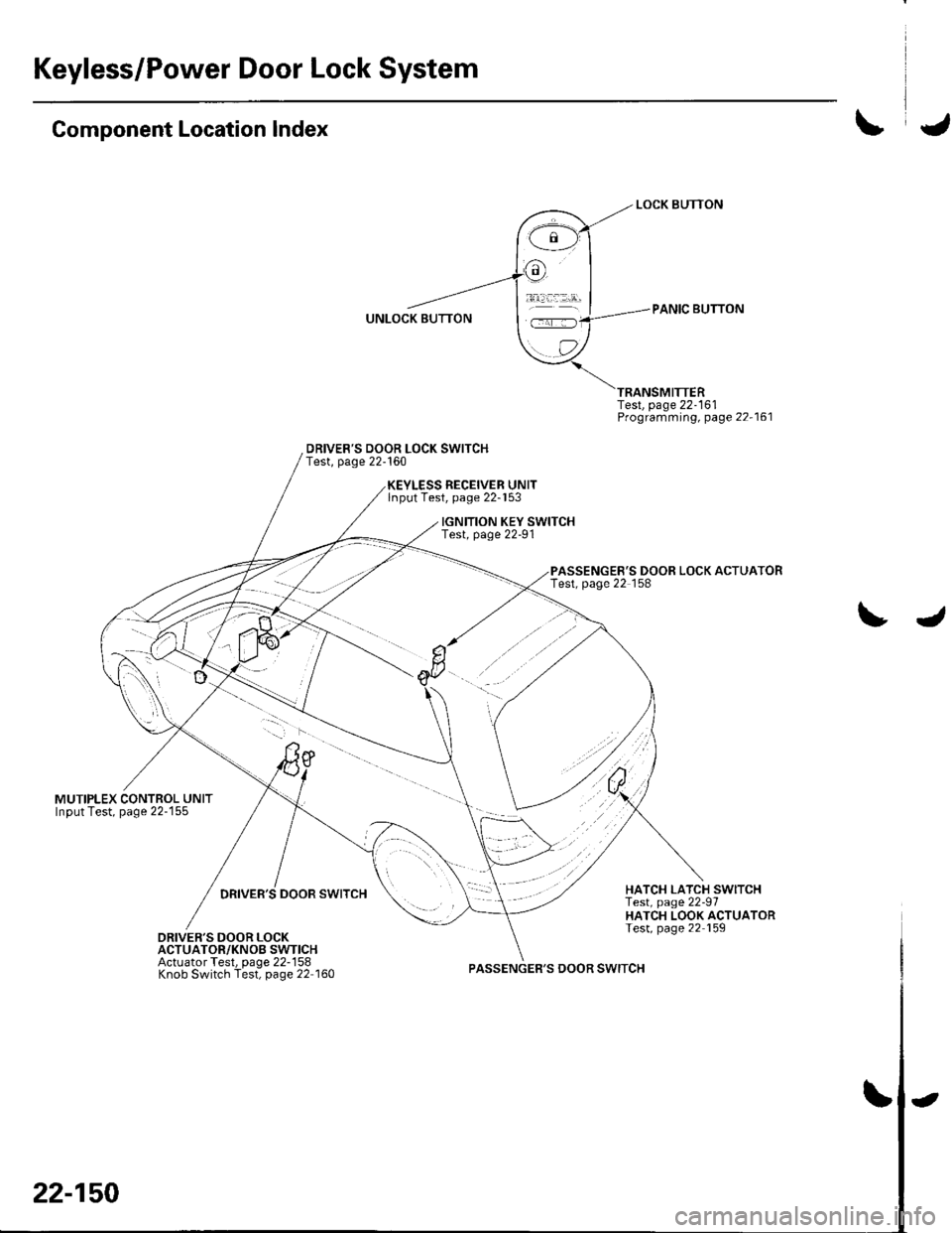
Keyless/Power Door Lock System
Component Location Index
MUTIPLEX CONTROL UNITInput Test, page 22-155
DRIVER'S DOOR LOCK SWITCHTest, page 22-160
Test, page 22-161Programming, page 22-161
PASSENGER'S DOOR LOCK ACTUATORTest, page 22 158
RECEIVER UNITlnput Test, page 22-153
IGNITION KEY SWITCHTest, page 22-91
DRIVER'S DOOR SWITCHHATCH LATCH SWITCHTest, page 22-97HATCH LOOK ACTUATORTest, page 22 159DRIVER'S DOOR LOCKACTUATOR/KNOB SWTICHActuator Test, page 22-158Knob Switch Test, page 22 160PASSENGER'S DOOR SWITCH
22-150
-
Page 983 of 1139
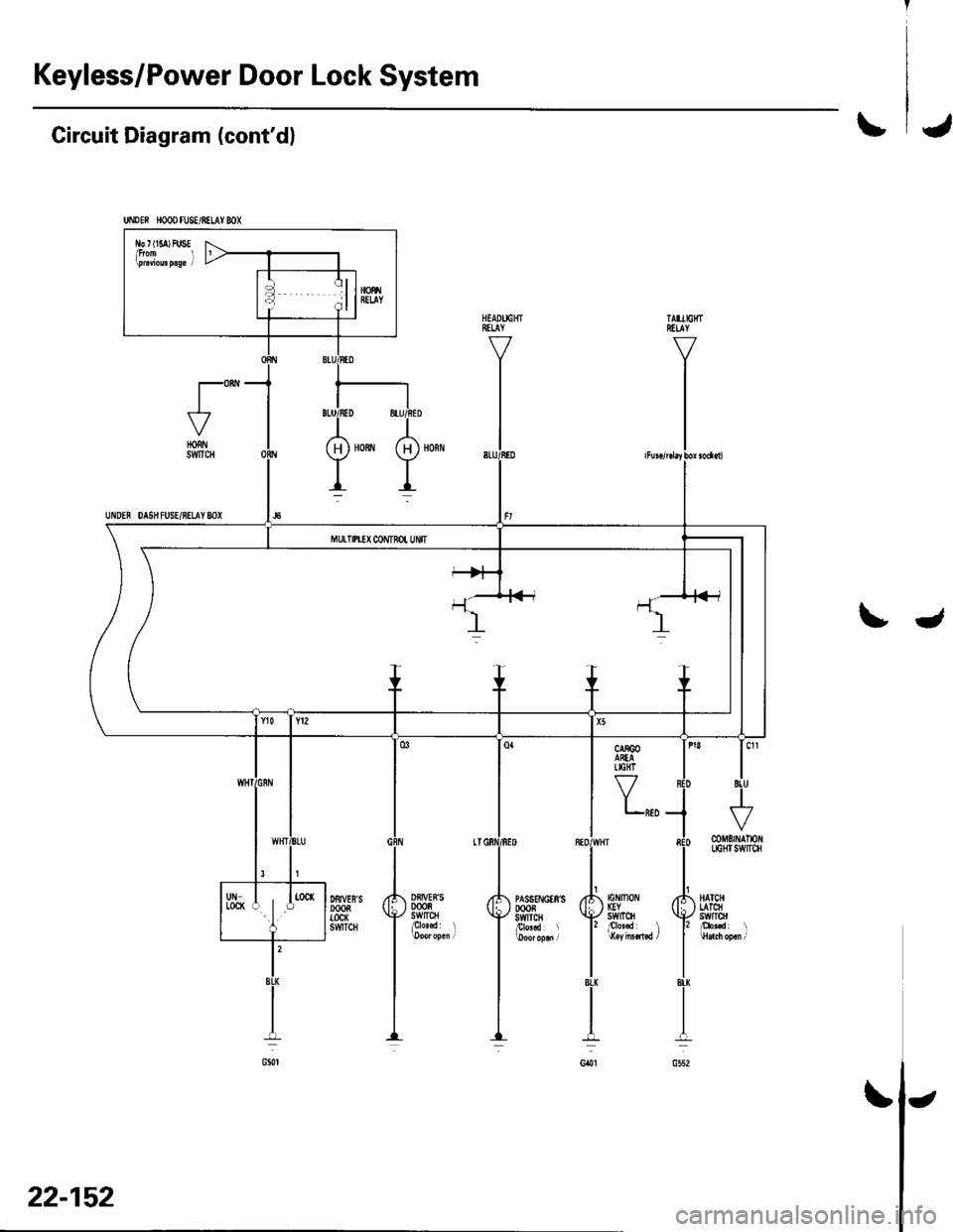
Keyless/Power Door Lock System
UNDEN HOOD FU8E/BELAY MX
l\b r t15a) FUSE
Circuit Diagram (cont'dl\J
t"-HORNSWTCH
UNDEN DAS}I FUSE/8ELAY 8OX
tJ
Y,,,
Df,IVEB'S0008swtrcHplo'.d l
DFIVES'SDOOBTOCK6WTCH
tG tltot IGYstvrTcH
mMErNAlloflLIGHI SWITCH
HATCHLATCHswlrol
22-152
\
Page 984 of 1139
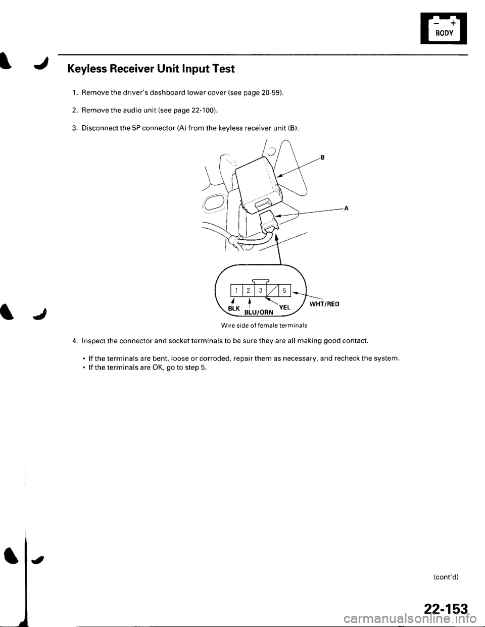
Keyless Receiver Unit Input Test
1. Remove the driver's dashboard lower cover (see page 20-59).
2. Remove the audio unit (see page 22-100).
3. Disconnect the 5P connector (A)from the keyless receiver unit (B).
WHT/RED
Wire side of female terminals
4. Inspecttheconnectorandsocketterminalstobesuretheyareall ma king good contact.
. lf the terminals are bent. Ioose orcorroded, repairthem as necessary, and recheckthe system.. lf the terminals are OK, go to step 5.
l
(cont'd)
t
22-153
Page 985 of 1139
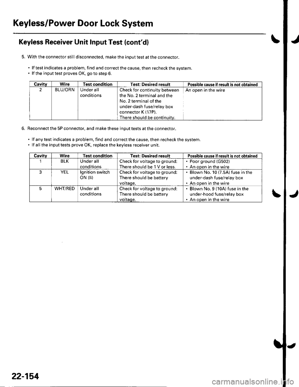
Keyless/Power Door Lock System
Keyless Receiver Unit Input Test (cont'dl
With the connector still disconnecled, make the input test at the connector.
.lftestindicatesaproblem,findandcorrectthecause,thenrecheckthesystem.
. lf the inputtest proves OK, goto step 6.
Reconnect the 5P connector, and make these input tests at the connector.
.lfanytestindicalesaproblem,findandcorrectthecause,thenrecheckthesystem.
. lf all the inputtests prove OK, replacethe keyless receiver unit.
CavityWireTest conditionTest: Desired resultPossible cause il result is not obtained
2BLU/ORNUnder all
conditions
Check for continuity between
the No.2 terminal and the
No. 2 terminal ofthe
under-dash fuse/relay box
connector K { 17P).
There should be continuitv.
An open in the wire
CavitvWireTest conditionTest: Desired resultPossible cause if result is not obtained
1BLKUnder all
conditions
Check for voltage to ground:
There should be 1 V or less.
. Poor ground (G502)
. An oDen in the wire
YELlgnition switch
oN (||)Check for voltage to ground:
There should be battery
voltaqe.
Blown No. 10 {7.5A) fuse in lhe
under-dash fuse/relay box
An ooen in the wire
WHT/REDUnder all
conditions
Check for voltage to ground:
There should be battery
voltaqe.
' Blown No.9 (10A) fuse in the
under-hood fuse/relay box. An ooen in the wire
22-154