ERS HONDA CIVIC 2003 7.G Workshop Manual
[x] Cancel search | Manufacturer: HONDA, Model Year: 2003, Model line: CIVIC, Model: HONDA CIVIC 2003 7.GPages: 1139, PDF Size: 28.19 MB
Page 834 of 1139
General Troubleshooting Information
Tips and Precautions
Bef ore Troubleshooting
1. Check applicable fuses in the appropriate fuse/relay
oox.
2. Check the battery for damage. state of charge, and
clean and tight connections.
. Do not quick-charge a battery unless the battery
ground cable has been disconnected, otherwise
you will damage the alternator diodes.. Do not attempt to crank the engine with the
battery ground cable loosely connected or you
will severely damage the wiring.
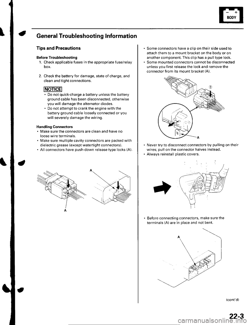
Handling Connectors. Make sure the connectors are clean and have no
loose wire terminals.. Make sure multiple cavity connectors are packed with
dielectric grease (except waterti ght connectors).. All connectors have push-down release type locks (A).
Some connectors have a clip on their side used to
attach them to a mount bracket on the body or on
another component. This clip has a pull type lock.
Some mounted connectors cannot be disconnected
unless you first release the lock and remove the
connector from its mount bracket (A).
Never try to disconnect connectors by pulling on their
wires; pull on the connector halves instead.
Alwavs reinstall Dlastic covers,
Before connecting connectors, make sure the
terminals (A) are in place and not bent.
(cont'd)
22-3
Page 835 of 1139
Body Electrical
General Troubleshooting Information (cont'd)
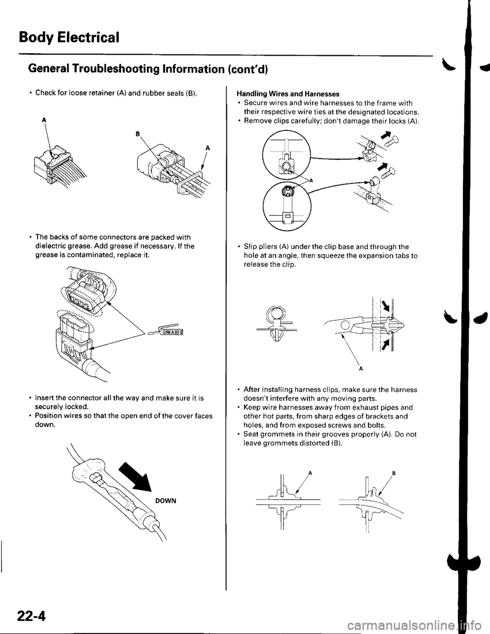
Check for loose retainer (A) and rubber seals (B).
The backs of some connectors are packed with
dielectric grease. Add grease if necessary. lf thegrease is contaminated, replace it.
lnsert the connector all the way and make sure it is
securelv locked.
Position wires so that the open end of the cover faces
oown.
22-4
Handling Wires and Harnesses. Secure wires and wire harnesses to lhe frame with
their respective wire ties at the designated locations.. Remove clips carefully; don't damage their locks (A).
Slip pliers (A) under the clip base and through the
hole at an angle, then squeeze the expansion tabs to
release the clip.
After installing harness clips, make sure the harness
doesn't interfere with any moving pans.
Keep wire harnesses away from exhaust pipes and
other hot parts, from sharp edges of brackets and
holes, and from exposed screws and bolts.
Seat grommets in their grooves properly {A). Do not
leave grommets distorted (B).
lt" /wl/
\--------\tfl r'---'..-
It
J
|,f . ./.ll t/
----E; F.�'l/
I
Page 837 of 1139
Body Electrical
General Troubleshooting Information (cont'dl
Five-step Troubleshooting
'1. Verify The Complaint
Turn on allthe components in the problem circuit
to verify the customer complaint. Note the
symptoms. Do not begin disassembly or testing
until you have narrowed down the problem area.
2. Analyze The Schematic
Look up the schematic for the problem circuit.
Determine how the circuit is supposed to work by
tracing the current paths from the power feed
through the circuit components to ground. lf
several circuits fail at the same time, the fuse or
ground is a Iikely cause.
Based on the symptoms and your understanding of
the circuit operation, identify one or more possible
causes of the problem.
3. lsolate The Problem By Testing The Circuit
Make circuit tests to check the diagnosis you made
in step 2. Keep in mind that a logical, simple
procedure is the key to efficient troubleshooting.
Test for the most likely cause of failure first, Try to
make tests at points that are easily accessible.
4. Fix The Problem
Once the specific problem is identified. make the
repair. Be sure to use proper tools and safe
proceoures.
5. Make Sure The Circuit Works
Turn on all components in the repaired circuit in all
modes to make sure you've fixed the entire
problem. lf the problem was a blown fuse, be sure
to test all of the circuits on the fuse. Make sure no
new problems turn up and the original problem
does not recur.
22-6
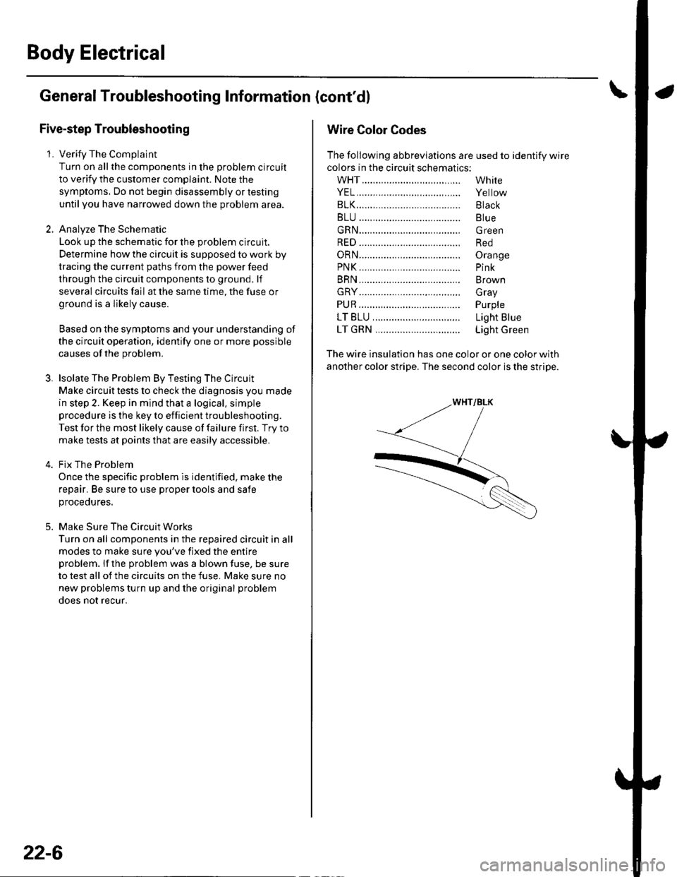
Wire Color Codes
The following abbreviations are used to identify wire
colors in the circuit schematics:
wHT....................,.,.............
YEL......................,,.......,......
B1K......................................
BLU ....,................................
GRN.....................................
RED ....................................,
oRN.....................................
PNK..........................,..........
BRN.....................................
GRY....................................,
PUR.....................................
1T81U..........................,.....
1TGRN...........................,...
White
Yellow
Black
Blue
Green
Red
Orange
Pink
Brown
Gray
Purple
Light Blue
Light Green
The wire insulation has one color or one color with
another color stripe. The second color is the stripe.
Page 844 of 1139
Gonnectors and Harnesses
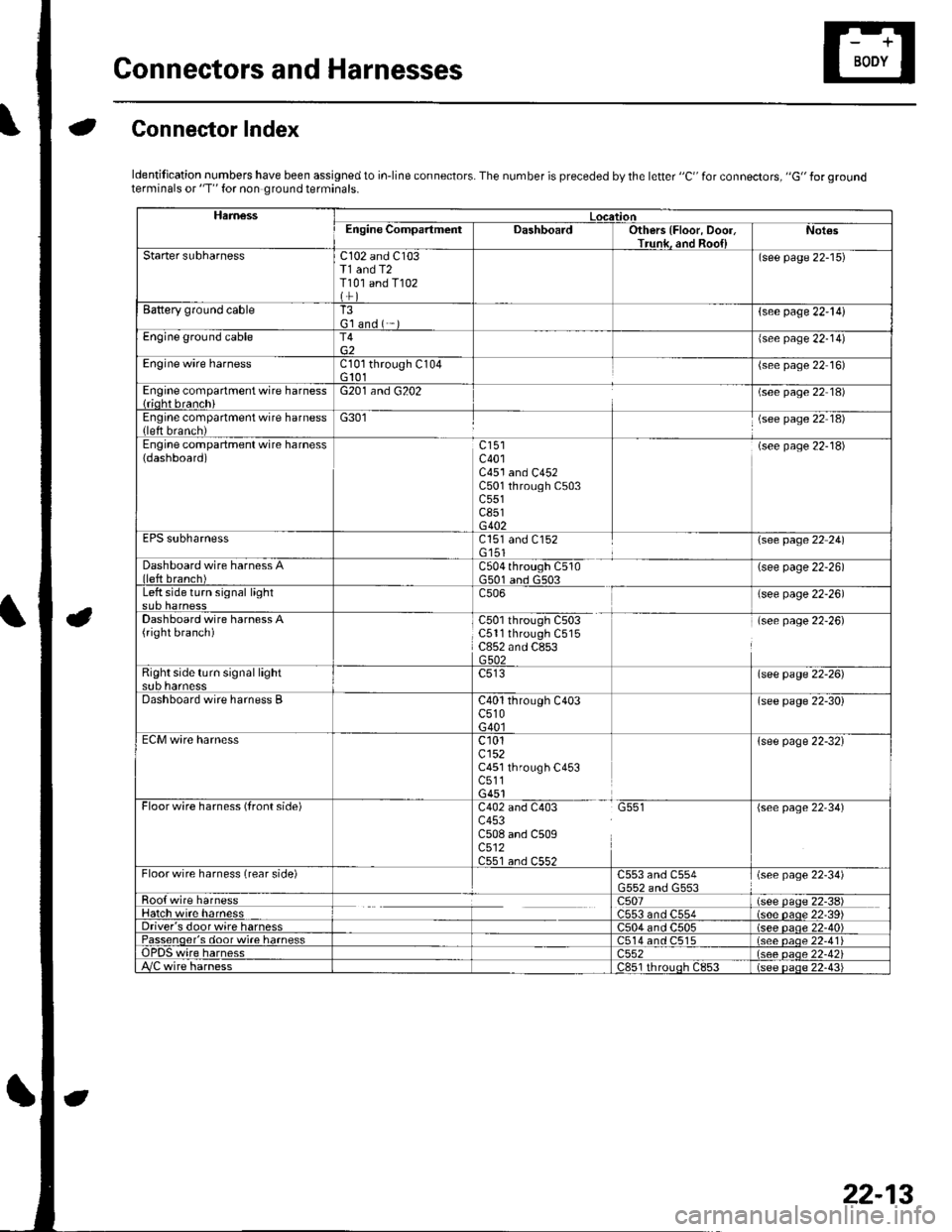
aGonnector Index
ldentification numbers have been assigned to in-line connectors. The number is preceded by the letter "C" for connectors, "G" for groundterminals or "T" for non ground terminals.
HamessLocationEngine CompartmentDashboardOthers {Floor, Door,Trunk. and Roo{lNot€s
Starter subharnessC102 and C103T1 and T2T101 and T102
(see page 22-15)
Battery ground cableT3G'l and ( -{see page 22-l!)
Engine ground cableT4{see page 22-14)
Engine wire harnessCl0l through C104G 101(see page 22 16)
Engine compartment wire harness{rioht branchiG201 and G202(see page 22 18)
Engine compartment wire harness(left brench)G301(see page 22 18)
Engine compartment wire harness(dashboard)c401C451 and C452C501 through C503c551c851G402
(see page 22-18)
EPS subharnessC151 and C152G'151\see page 22 241
Dashboard wire harness Alleft branch)C504 through C510G501 and G503(see page 22-26)
Left side turn signal lightc506(see page 22-26)
Dashboard wire harness A(right branch)C50l through C503C5ll through C515C852 and C853G502
(see page 22-26)
Right side turn si9nal lightsub harnesslsee page 22-26)
Dashboard wire harness BC40l through C403c510G40l
(see page 22-30)
ECM wire harnessc101cl52C451 through C453c511G451
{see page 22-32}
Floorwire harness (front side)C402 and C403 G551c453C508 and C509c512C551 an.l C55?
(see page 22'34)
Floor wire harness (rear side)C553 and C554(see page 22-34)
Roo{ wire harnessc507(see paqe 22-38)Hatch wire harnessC553 and C554(s6e paqe 22'39)Driver's door wire harnessC504 and C505(see paqe 22-40)Passenqer's door wi.e harness514 and C515(see oaoe 22-41Te harness)552(see oaqe 22-42i/C wire harnessc851 rhrouoh c853(see paqe 22.43i
22-13
Page 865 of 1139
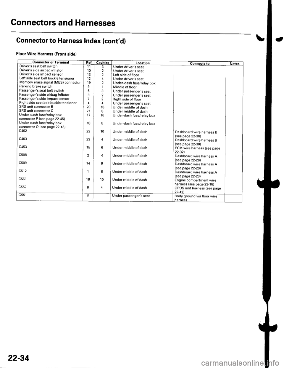
Connectors and Harnesses
Connector to Harness lndex (cont'd)
Floor Wire Harness (Front sidel
Connec-tor or TerminalI Refuavftres Location connects to Nol6sDriver's seat belt switchDriver's side airbag inflatorDriver's side impact sensorLeft side seat belt buckle tensionerMemory erase signal (MES) connectorParking brake switchPassenger's seat belt switchPassenger's side airbag inflatorPassenger's side impact sensorRight side seat belt buckle tensionerSRS unit connector BSRS unit connector CUnder-dash fuse/relay boxconnector P {see page 22-45)Under-dash fuse/relay boxconnector O (see page 22,45)c402
c403
c453
c508
c509
c512
11l013121995374202111
'r8
22
23
2
14
1
6
3 I Under driver's seat2 i Under driver's seat2 I Left side offloor4 Under driver's seat2 Under dash fuse/relay box1 1 Middle offloor3 Under passenger's seat2 Under passenger's seat2 Right side offloor4 Under passenger's seat18 I Under middle of dash8 Under middle of dash18 Underdash fuse/relay box
8
]
Under dash fuse/relay box
10
I
Under middle of dash
4 Under middle of dash
6 Under middle of dash
4 Under middle of dash
6 Under middle ofdash
8
I
Under middle of dash
10 Under middle of dash
4 ] Unaer middle of aasn
Dashboard wire harness B{see page 22 30)Dashboard wire harness B(see page 22-30)ECM wire harness (see page22-321Dashboard wire harness A(see page 22-26)Dashboard wire harness A\see page 22-26)Dashboard wire harness A{see page 22-26)Engine compartment wireharness (see page 22 18)OPDS unit harness (see page22-421G551IL,nder passenger's seatBody ground via floor wire
22-34
Page 880 of 1139
Under-dash Fuse/Relay Box
Removal and Installation
SRS components are located in this area. Review the
SRS component locations {see page 23-13) andprecautions and procedures (see page 23-14) in the SRS
section before performing repairs or service.
Removal
1. Make sure you have the anti-theft code for the radio,
then write down the frequencies for the radio's
preset buttons.
2. Disconnectthe battery negative cable, then
disconnect the positive cable, and wait at least
three minutes.
3. Remove the driver's dashboard lower cover (see
page 20-59).
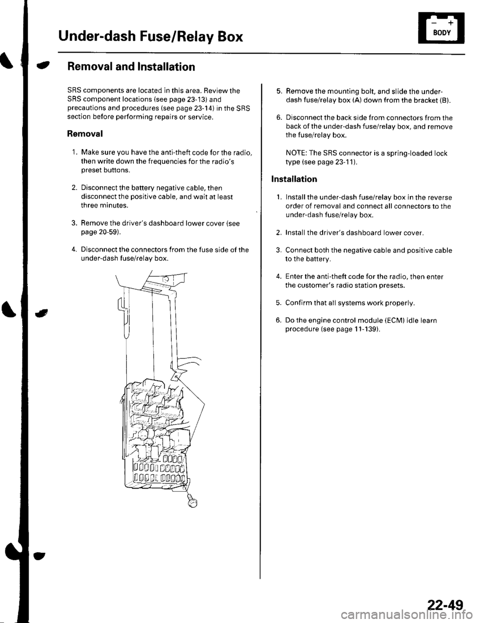
4. Disconnect the connectors from the fuse side of the
under-dash fuse/relay box.
5. Remove the mounting bolt, and slide the under-
dash fuse/relay box (A) down from the bracket {B).
6. Disconnect the back side from connectors from the
back of the under-dash fuse/relay box, and remove
the fuse/relay box.
NOTE:The SRS connector is a spring-loaded lock
type (see page 23-1 1).
lnstallation
1. Installthe under-dash fuse/relay box in the reverse
order of removal and connect all connectors to the
under-dash fuse/relay box.
2. Installthe driver's dashboard lower cover.
3. Connect both the negative cable and positive cable
to the battery.
4. Enter the anti-theft code for the radio, then enter
the customer's radio station presets.
5. Confirm that all systems work properly,
6. Do the engine control module (ECM) idle learn
procedure (see page 11-139).
22-49
Page 881 of 1139
Battery
{Battery Test
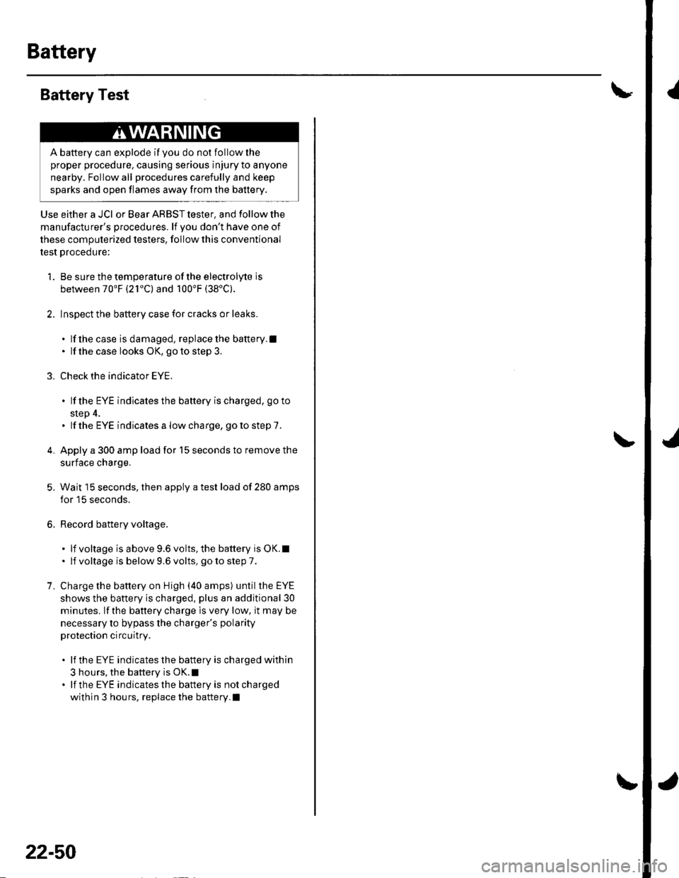
Use either a JCI or Bear ARBST tester, and follow the
manufacturer's procedures. lf Vou don't have one of
these computerized testers, follow this conventional
test procedure:
1. Be sure the temperature of the electrolyte is
between 70'F (21"C) and 100'F (38'C).
2. Inspect the battery case for cracks or leaks.
. lf thecase isdamaged, replacethe battery.l. lf the case looks OK, go to step 3.
3. Check the indicator EYE.
. lf the EYE indicatesthe baftery ischarged, goto
step 4.. lf the EYE indicatesa lowcharge, gotostep7.
4. Apply a 300 amp load for 15 seconds to remove the
surface charge.
5, Wait 15 seconds, then apply a test load of 280 amps
for 15 seconds.
6. Record battery voltage.
. lf voltage is above9.6volts,the battery isOK.l. lf voltage is below9.6volts, gotostepT.
7. Charge the battery on High (40 amps) until theEYE
shows the battery is charged, plus an additional 30
minutes. lf the battery charge is very low, it may be
necessary to bypass the charger's polarity
protection circuitry.
. lf the EYE indicatesthe battery is chargedwithin
3 hours, the battery is OK.l. lf the EYE indicatesthe battery is notcharged
within 3 hours, replace the battery.l
A battery can explode if you do not follow the
proper procedure, causing serious injury to anyone
nearby. Follow all procedures carefully and keep
sparks and open flames away from the battery.
22-50
Page 882 of 1139
Relays
Power Relay Test
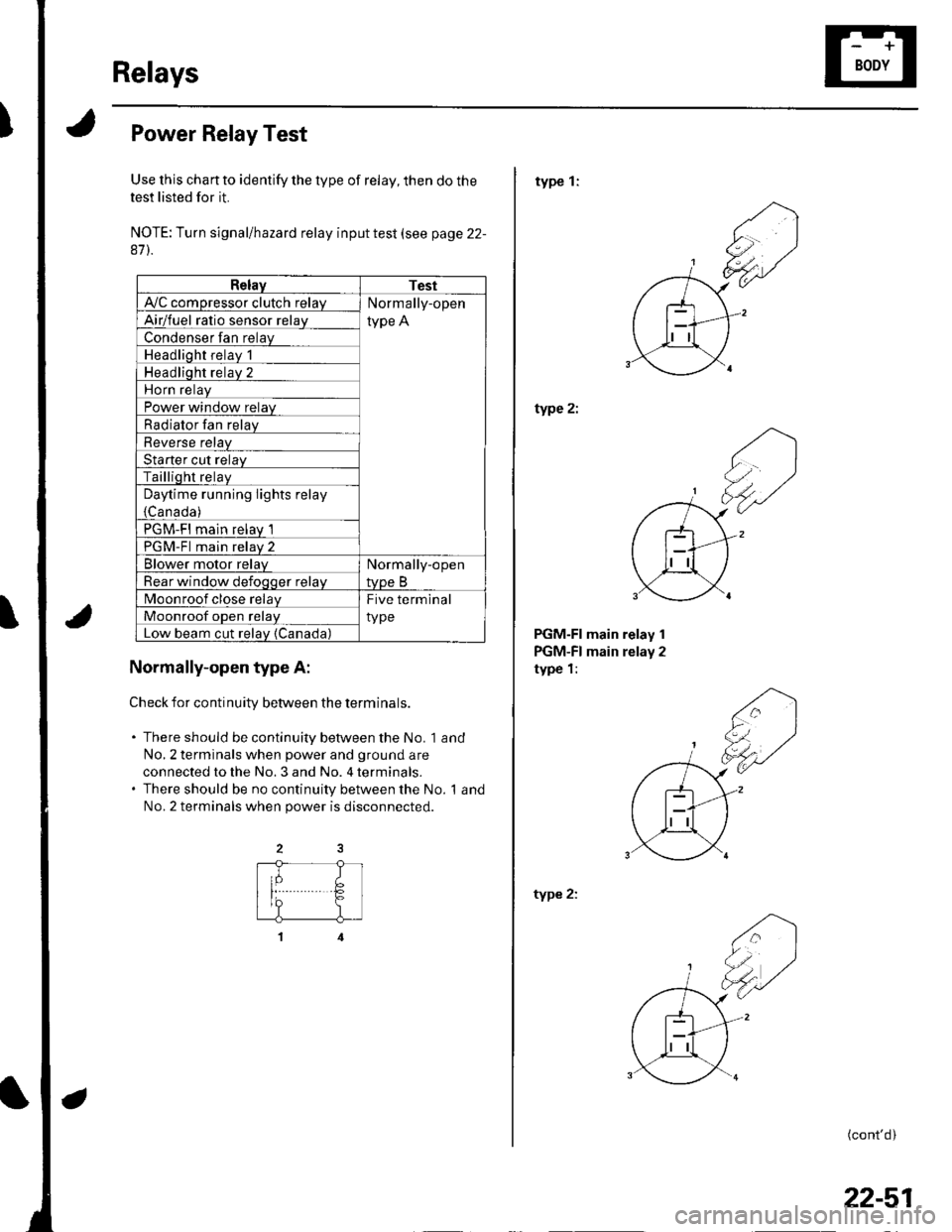
Use this chan to identify the type of relay, then do the
test listed for it.
NOTE: Turn signal/hazard relay input test (see page 22-
87).
RelayTest
A'lC comoressor clutch relavNormally-open
type AAirlfuel ratio sensor relav
Condenser fan relay
Headlioht relav 1
Headliqht relav 2
Horn relav
Power window relay
Radiator Ian relay
Reverse relav
Starter cut relav
Tailliqht relaV
Daytime running lights relay
{Canada )
PGM-FI main relav 1
PGM-Fl main relav 2
Blower motor relavNormally-open
tvpe BRear window defoqoer relav
Moonroof close relayFive terminal
typeMoonroof oDen relav
Low beam cut relav {Canada)
Normally-open type A:
Check for continuitv between the terminals.
. There should be continuity between the No. 1 and
No,2 terminals when power and ground are
connected to the No. 3 and No. 4 terminals.. There should be no continuity between the No. 1 and
No.2 terminals when power is disconnected.
type 1:
type 2:
PGM-FI main relay 1
PGM-FI main relay 2
type 1:
type 2:
(cont'd)
22-51
Page 892 of 1139
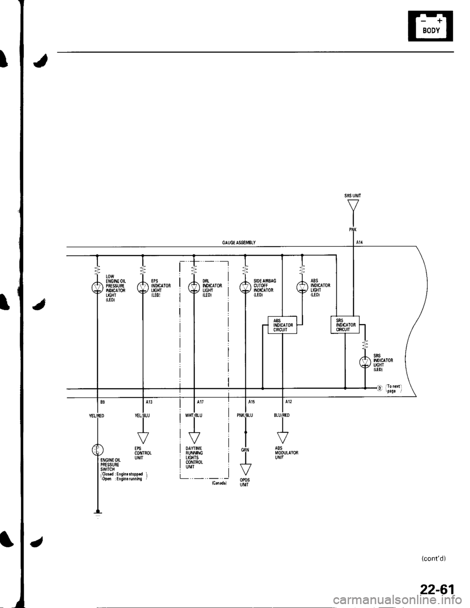
'- --t
I DAYTIME I! BUNN|NG ;i LIGHTS II @NTROLI UNII iL -.-.. Iicmadd
./ ib-n'rnoLtNGniEorL UNITPRESSUBEswtTcHlCld.d Eisin.3topp.d liopd Ersin.runni.s i
(cont'd)
22-61
Page 895 of 1139
Gauges
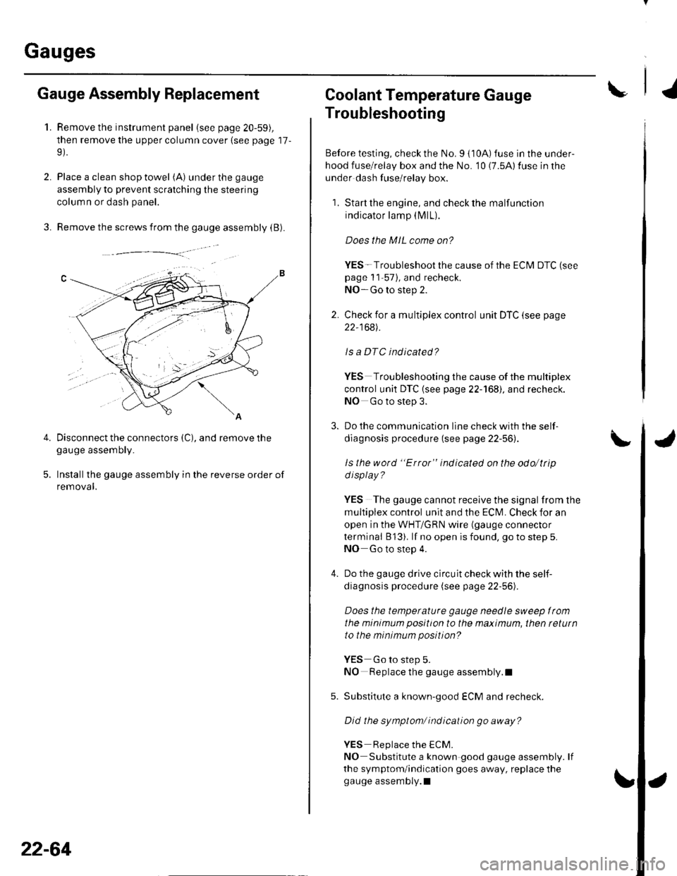
2.
3.
Gauge Assembly Replacement
1.Remove the instrument panel (see page 20-59),
then remove the upper column cover {see page 17-
Place a clean shop towel (A) under the gauge
assembly to prevent scratching the steering
colum n or dash panel.
Remove the screws from the gauge assembly (B).
Disconnect the connectors (C), and remove thegauge assemDry.
Installthe gauge assembly in the reverse order of
removal.
Coolant Temperature Gauge
Troubleshooting
Before testing, check the No. I { 10A) fuse in the under-
hood fuse/relay box and the No. '10 (7.5A) fuse in the
under dash fuse/relay box.
1. Start the engine, and check the malfunction
indicator lamp (MlL).
Does the MIL come on?
YES- Troubleshoot the cause of the ECM DTC (see
page 1 1-57), and recheck.
NO-Go to step 2.
2. Check for a multiplex control unit DTC (see page
22,168).
ls a DTC ind icated?
YES Troubleshooting the cause of the multiplex
control unit DTC {see page 22-168), and recheck.
NO Go to step 3.
3. Do the communication line check with the self-
diagnosis procedure (see page 22-56).
ls the word "Error" indicated on the odo/ttip
d isplay ?
YES The gauge cannot receive the signal from the
multiplex control unit and the ECI\,4. Check for an
open in the WHT/GRN wire (gauge connector
terminal B 13). lf no open is found, go to step 5.
NO Go to step 4.
4. Do the gauge drive circuit check with the self-
diagnosis procedure (see page 22-56).
Does the temperature gauge needle sweep lrom
the minimum position to the maximum, then tetutn
to the minimum position?
YES Go to step 5.
NO Replace the gauge assembly.l
5. Substitute a known-good ECM and recheck.
Did the symptom/ ind ication go away?
YES Replace the ECM.
NO Substitute a known good gauge assembly. lf
the symptom/indication goes away, replace thegauge assembly.l
4.
22-64