ERS HONDA CIVIC 2003 7.G Workshop Manual
[x] Cancel search | Manufacturer: HONDA, Model Year: 2003, Model line: CIVIC, Model: HONDA CIVIC 2003 7.GPages: 1139, PDF Size: 28.19 MB
Page 898 of 1139
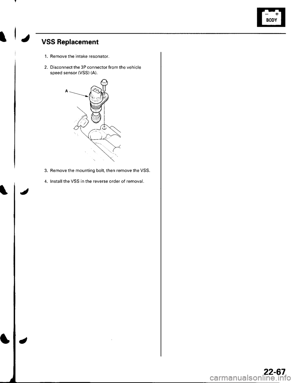
IJVSS Replacement
1. Remove the intake resonator.
2. Disconnect the 3P connector from the vehicle
speed sensor {VSS) (A).
4.
Remove the mounting bolt, then remove the VSS.
lnstallthe VSS in the reverse order of removal.
22-67
Page 910 of 1139
5
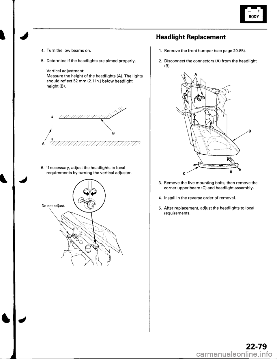
Turn the low beams on.
Determine ifthe headlights are aimed properly.
Vertical adjustment:
Measure the height ofthe headlights (A). The lights
should reflect 52 mm (2.'1 in.) below headljght
height (B).
6. lf necessary, adjust the headlights to local
requirements by turning the vertical adjuster.
i
Headlight Replacement
Remove the front bumper (see page 20-85).
Disconnect the connectors (A) from the headlight(B).
Remove the five mounting bolts, then remove the
corner upper beam (C) and headlight assembly.
Install in the reverse order of removal.
After replacement, adjust the headlights to local
requirements.
'1.
2.
5.
22-79
Page 911 of 1139
Exterior Lights
4.
5.
Combination Light Switch Test/Replacement
1. Remove the driver's dashboard lower cover (see page 20-60).
2. Remove the steering column covers (see page 17-9).
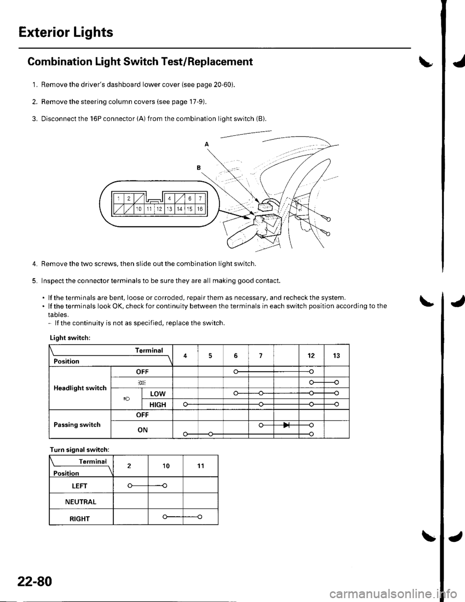
3, Disconnectthe l6Pconnector(A) f rom the combination light switch (B).
Remove the tlvo screws, then slide out the combination light switch.
Inspect the connector terminals to be sure they are all making good contact.
. lf the terminals are bent, loose or co rroded, repa ir them as necessa ry, a nd recheck the system..lftheterminalslookOK,checkforcontinuitybetweentheterminalsineachswitchpositionaccordingtothe
tables.- lf the continuity is not as specified, replace the switch.
Light switch:
Telmint
Position451213
Headlight switch
OFF
LOWo--
HIGHo--
Passing switch
OFF
ONo-
Turn signalswitch:
Terminal
Position21011
LEFT----o
NEUTRAL
RIGHTo--
22-80
Page 912 of 1139
Bulb Replacement
Headlight:
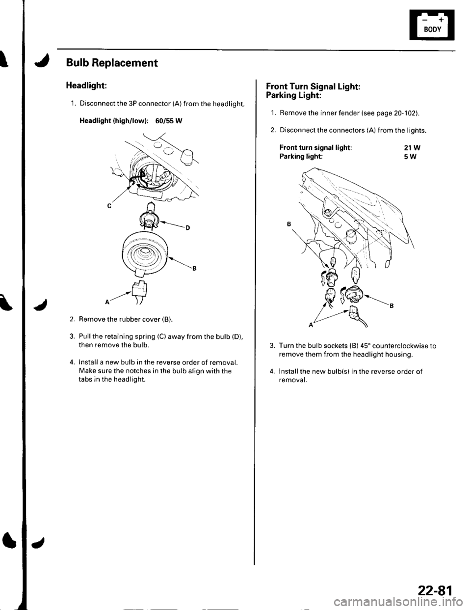
1. Disconnect the 3P connector (A) from the headlight.
Headlight {high/low): 60/55 W
f-rI-'-+lA- )/
Remove the rubber cover (B).
Pull the retaining spring (C) away from the bulb (D),
then remove the bulb.
Install a new bulb in the reverse order of removal.
Make sure the notches in the bulb align with the
tabs ln the headlight.
2.
Front Turn Signal Light:
Parking Light:
1. Remove the inner fender (see page 20-102).
2. Disconnectthe connectors (A) from the lights.
21W
5W
4.
Front turn signal light:
Parking light:
Turn the bulb sockets (B) 45'counterclockwise to
remove them from the headlight housing.
Installthe new bulb(s) in the reverse order of
removat.
22-81
Page 913 of 1139
Exterior Lights
1.
2.
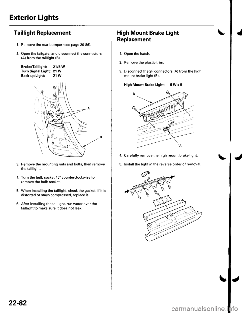
Taillight Replacement
Remove the rear bumper (see page 20-86).
Open the tailgate, and disconnect the connectors(A) from the taillight (B).
Brako/Taillight; 2115W
Turn Signal Light: 21 W
Back-up Light: 21W
Remove the mounting nuts and bolts, then remove
the taillight.
Turn the bulb socket 45' counterclockwise to
remove the bulb socket.
When installing the taillight. check the gasket; if it is
distorted or stays compressed, replace it.
After installing the taillight. run water over the
taillight to make sure it does not leak.
=\
ili--- _ \
rB , \.
---'a t
\
22-82
High Mount Brake Light
Replacement
1. Open the hatch.
2. Remove the plastic trim.
3. Disconnectthe 2P connectors (A)from the high
mount brake light (B).
High Mounl Brake Light: 5 W x 5
Carefully remove the high mount brake light.
lnstall the light in the reverse order of removal.5.
'
Page 914 of 1139
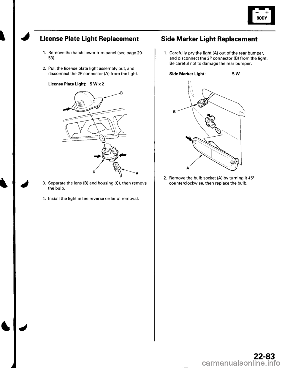
License Plate Light Replacement
1.Remove the hatch lower trim panel (see page 20-
Pullthe license plale light assembly out. and
disconnect the 2P connector (A) from the light.
License Plate Light: 5Wx2
3.
4.
'[-J^,^f , t lo \
+tiP'-t \-J'fl^
"/ \==-^
Separate the lens (B) and housing (C), then remove
the bulb.
lnstallthe light in the reverse order of removal.
Side Marker Light Replacement
1. Carefully pry the light (A) outofthe rear bumper,
and disconnect the 2P connector (B) from the light.
Be careful not to damage the rear bumper.
Side Marker Light:5W
2.Remove the bulb socket (A) by turning it 45'
counterclockwise. then reolace the bulb.
22-83
Page 921 of 1139
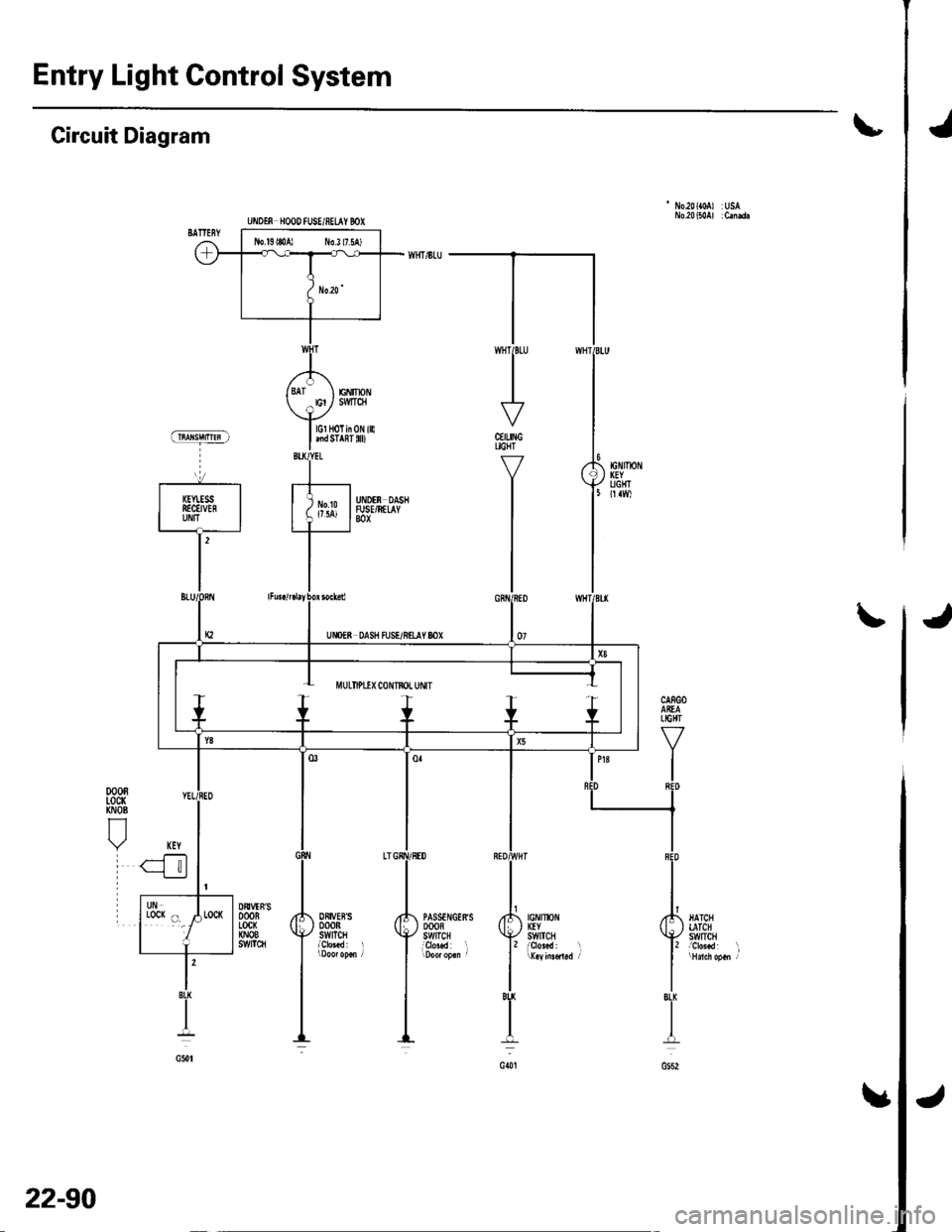
Entry Light Control System
Jt
'No.20({0A) USA
Circuit Diagram
CEILINGUGHT
Y
I
I
J\
jIGNIlx)NKEYSWtTCH
PASSTNGERSDOOBSWITCHi9r"..d l
ORIVEBSDOORSWITCH
DtrVTN'SDOORLocx(NOBs!t/tTc8
l'BU
I
G()t
lGl HoTin 0N illlnd STAnT 0D
EiIIpNSMTqI
UiIOTf, HOOD fUSE/8ELAY BOX
J
22-90
Page 922 of 1139
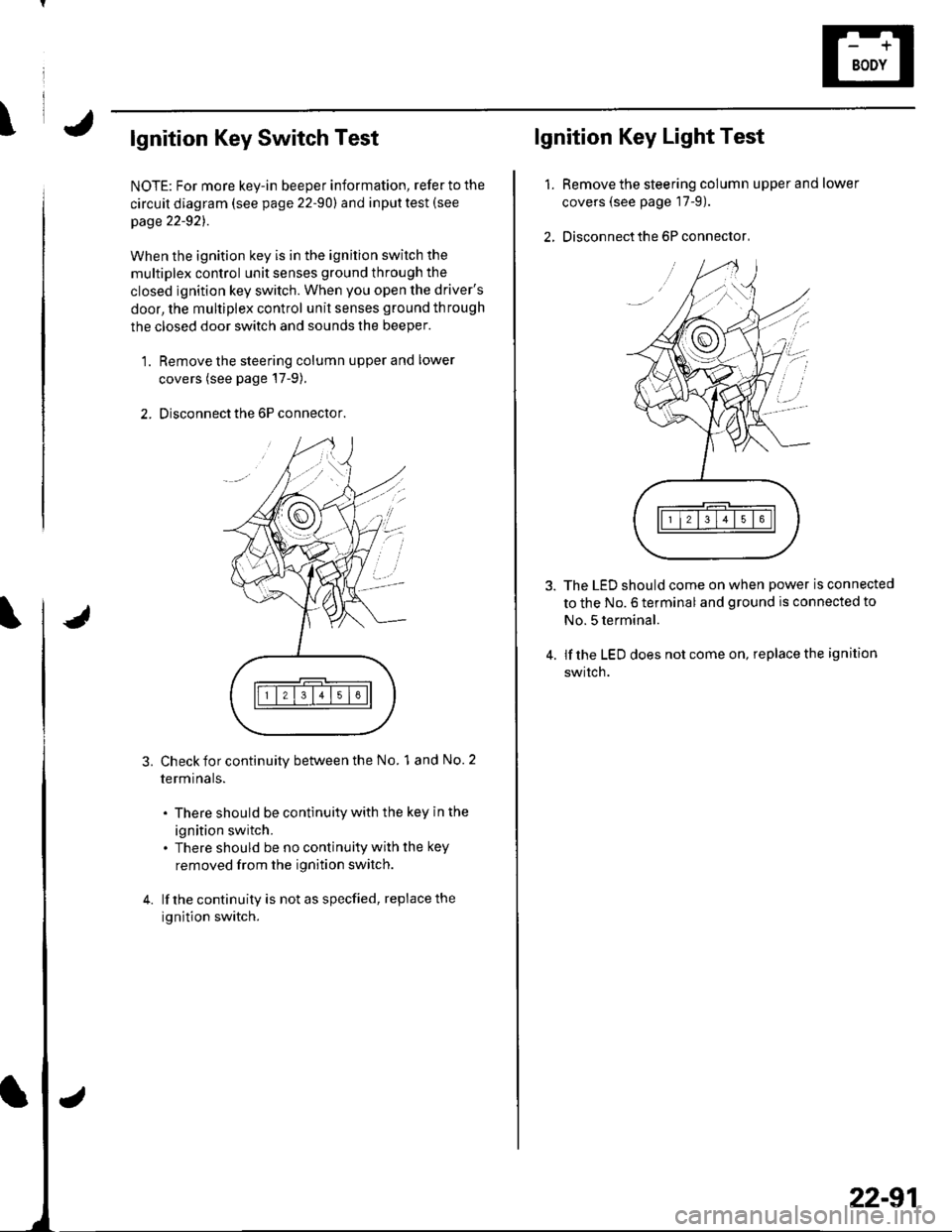
\lgnition Key Switch Test
NOTE: For more key-in beeper information, refer to the
circuit diagram (see page 22-90) and input test (see
page 22-921.
When the ignition key is in the ignition switch the
multiplex control unit senses ground through the
closed ignition key switch. When you open the driver's
door, the multiplex control unit senses ground through
the closed door switch and sounds the beeper.
1. Remove the steering column upper and lower
covers (see page'17-9).
2. Disconnect the 6P connector.
3.Check for continuity between the No. 1 and No. 2
termrnars.
. There should be continuity with the key in the
ignition switch.. There should be no continuity with the key
removed from the ignition switch.
lf the continuity is not as specfied, replace the
ignition switch.
lgnition Key Light Test
1.Remove the steering column upper and lower
covers (see page 17-9).
Disconnect the 6P connector,
The LED should come on when power is connected
to the No. 6 terminal and ground is connected to
No. 5 terminal.
lf the LED does not come on, replace the ignition
swrtch.
i'
/.'
22-91
Page 931 of 1139
Audio System
Audio Unit Removal/lnstallation
NOTE:. Put on gloves to protect your hands.. Take care not to scratch the dashboard and relatedpa rts.
1. Make sure you have the anti-theft code for the radio,
then write down the frequencies for the radio's
preset buttons.
2. Remove the driver's dashboard lower cover (see
page 20-59).
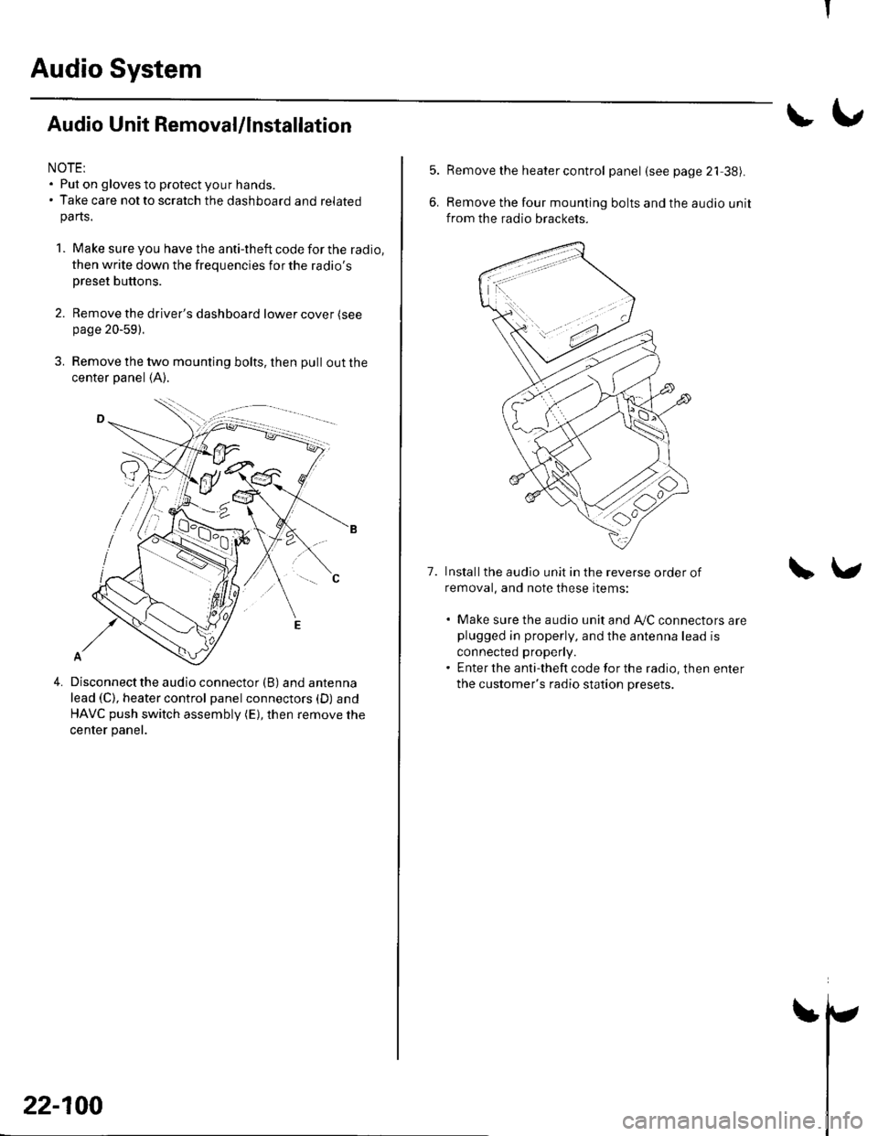
3. Remove the two mounting bolts, then pull out the
center panel (A).
4.Disconnect the audio connector (B) and antenna
lead (C), heater control panel connectors (D) and
HAVC push switch assembly (E), then remove the
center panel.
22-100
!\,
7.
Remove the heater control panel (see page 21 38).
Remove the four mounting bolts and the audio unit
from the radio brackets.
Installthe audio unit in the reverse order of
removal, and note these items:
. Make sure the audio unit and A/C connectors areplugged in properly, and the antenna lead is
connected properly.. Enter the anti-theft code for the radio, then enter
the customer's radio station presets.
\v
I
Page 937 of 1139
Rear Window Defogger
Function Test
NOTE:. Be careful not to scratch or damage the defogger
wires with the tester probe.
. Before testing, check the No. 11 (30A) fuse in the
under-hood fuse/relay box and No. '14 ('10A) fuse in
the under-dash fuse/relay box.
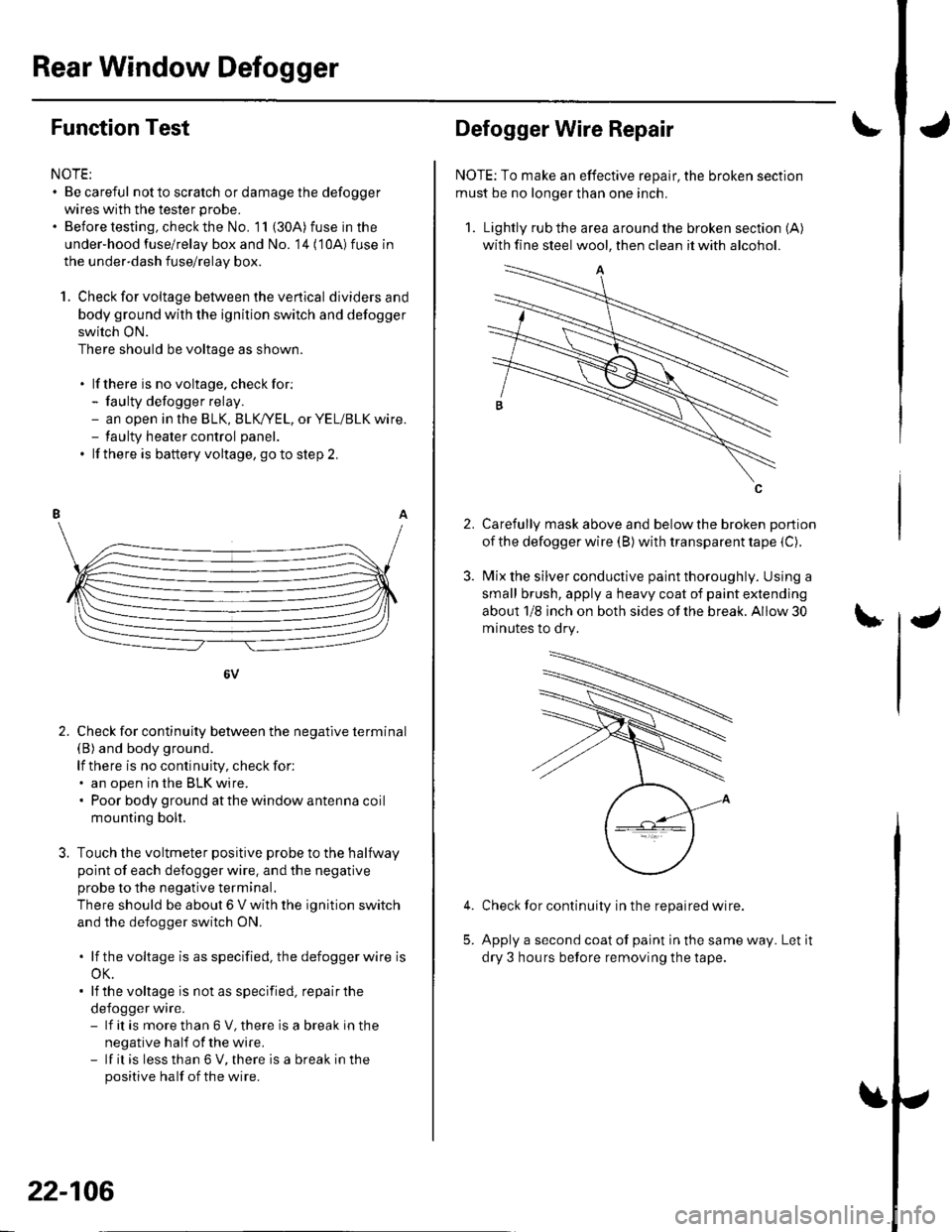
1. Check for voltage between the ve rtica I dividersand
body ground with the ignition switch and defogger
switch ON.
There should be voltage as shown.
. lf there is no voltage. checkfor:- faulty defogger relay.- an open in the BLK, BLK,/YEL, or YEL/BLK wire.- taulty heater control panel.
. lf there is battery voltage, goto step 2.
6V
Check for continuity between the negative terminal(B) and body ground.
lf there is no continuity, check for:. an open in the BLK wire.. Poor body ground at the window antenna coil
mounting bolt.
Touch the voltmeter positive probe to the halfway
point of each defogger wire. and the negative
probe to the negative terminal,
There should be about 6 V with the ignition switch
and the defogger switch ON.
. lf thevoltage is asspecified, the defoggerwlre is
oK.. lf the voltage is not as specified, repair the
defogger wire.- lf it is more than 6 V, there is a break in the
negative half of the wire.- lf it is less than 6 V, there is a break in the
positive half of the wire.
2.
22-106
2.
Defogger Wire Repair
NOTE: To make an effective repair, the broken section
must be no longer than one inch.
1. Lightly rub the area around the broken section (A)
with fine steel wool, then clean it with alcohol.
Carefully mask above and below the broken portion
of the defogger wire (B) with transparent tape {C).
Mix the silver conductive paint thoroughly. Using a
small brush, apply a heavy coat of paint extending
about 1/8 inch on both sides of the break. Allow 30
minutes to dry.
Check for continuity in the repaired wire.
Apply a second coat of paint in the same way. Let it
dry 3 hours before removing the tape.
5.