brake fluid HONDA CIVIC 2003 7.G Owner's Manual
[x] Cancel search | Manufacturer: HONDA, Model Year: 2003, Model line: CIVIC, Model: HONDA CIVIC 2003 7.GPages: 1139, PDF Size: 28.19 MB
Page 618 of 1139
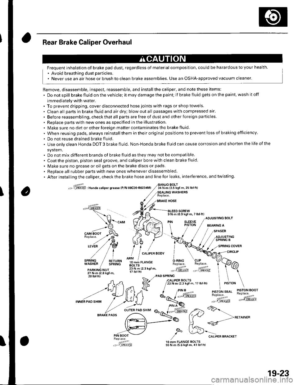
Rear Brake Caliper Overhaul
Frequent inhalation of brake pad dust, regardless of material composition, could be hazardous to your health.
' Avoid breathing dust particles.
. Never use an air hose or brush to clean brake assemblies. Use an OSHA-approved vacuum cleaner'
Remove, disassemble, inspect, reassemble, and installthe caliper, and note these items:
. Donotspill brake fluid on the vehicle; it may damage the paint; if brake f luid gets on the paint, wash it off
immediately with water.. To prevent dripping. cover disconnected hose joints with rags or shop towels.
. Cleanall partsinbrakefluidandairdry;blowoutall passageswith compressed air'
. Before reassembling, check that all parts are free of dust and other foreign particles
. Replace pans with new ones as specified in the illustration.. Make sure no dirt or other foreign matter contaminates the brake fluid.
. When reusing pads, always reinstallthem in their original positions to prevent loss of b ra king efficie ncy.
. Do not reuse drained brake fluid.
. Use only clean Honda DOT 3 brake fluid. Non-Honda brake fluid can cause corrosion and shorten the life of the
system.. Do not mix different brands ot brake fluid as they may not be compatible.
. Coatthe piston, piston seal groove, and caliper bore with clean brake fluid.
. Make sure no grease or oil gets on the brake discs or pads.
. Replaceall rubber parts with new ones whenever disassembled.
. After installing the caliper, check the brake hose and line for leaks, interference. and twisting.
oG , nonau."rip6r qreas€ lP/N 08c30-aoa4Ml34 N.m (3.5 kgf m,25lbtft)BOLT
WASHERS
BRAKE HOSE
a
l,i,,'IltE" / !!;,ff
olT-J,.o"c.O.RING CUPBeplace. Beplace.
.ARKING NUr lii.'i rz.r rgr.. Gd ffi27Nm{2.8kgtm,
\-"o, V((rA ",1 ;[.,.JF /;;;;---
t H\a \l / t,i*t'*"
?,,.t/*"^.,,.:,"", /"V4#
ADJUSTING BOLT
,/
27Nm{2.8kgf.m,20 tbf.ftr PAD SPRING
A,n Na 7lfl,lif,loffi ',,0,n, ,,:,o" \
--t)(*ff l^7k ''"'t!1'ry#'
INNEBPA'SHIM
/ .r.:._U i*E'( ":;*" *dF ,.2>a>-
fr.x{_>@ fftt **-->**^'"
,,.-"iV ,/q &'"o.,"."""o"^.,
: 10 MM FLANGE BOLTS.:r=,9!q!q}l 55 N m (5.6 lgf-m, 4r lbt ft)
19-23
Page 620 of 1139
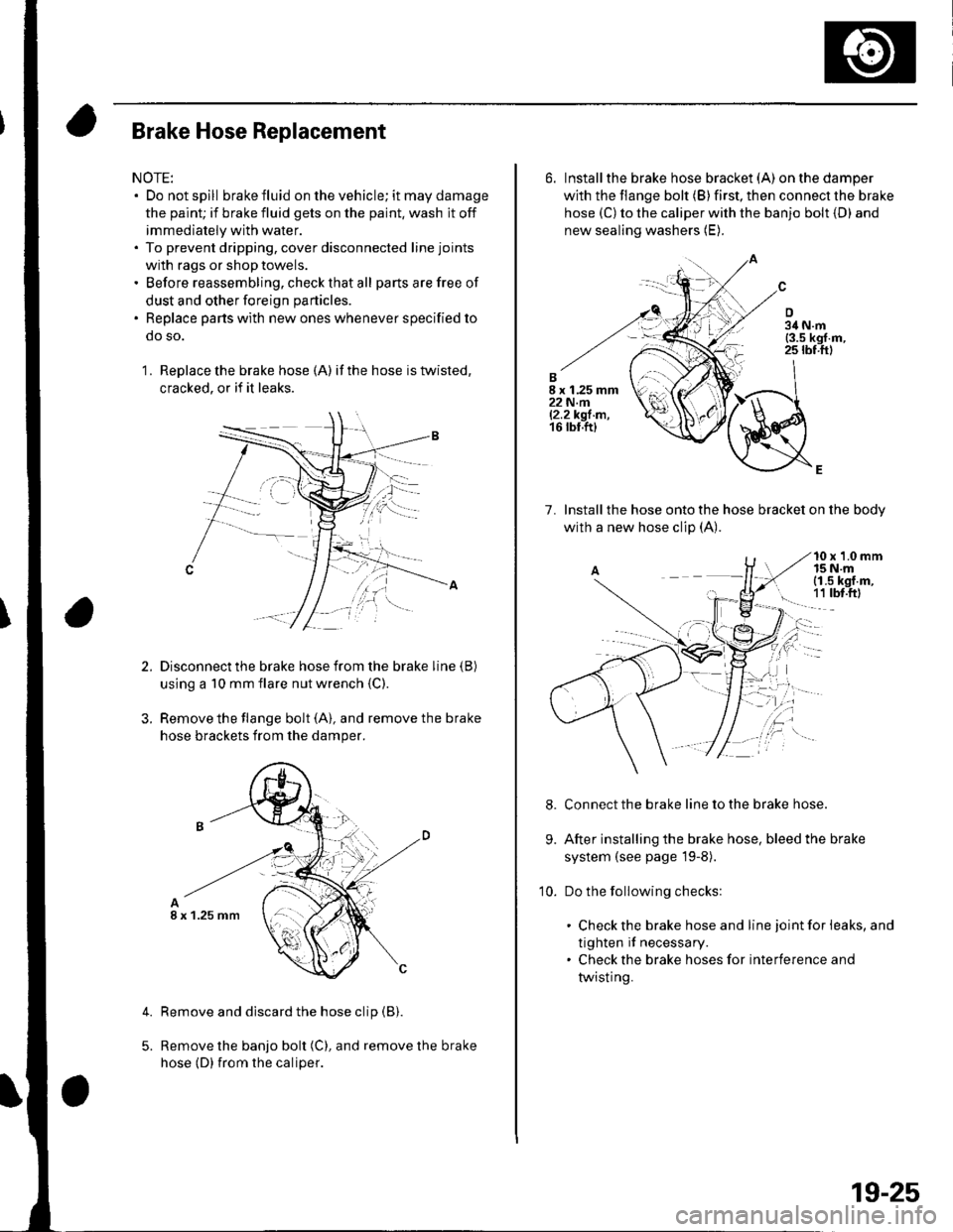
Brake Hose Replacement
NOTE:. Do not spill brake fluid on the vehicle; it may damage
the paint; if brake fluid gets on the paint, wash it off
immediately with water.. To prevent dripping, cover disconnected line joints
with rags or shop towels.. Before reassembling, check that all parts are free of
dust and other foreign particles.
. Replace parts with new ones whenever specified to
do so.
1 . Replace the brake hose (A) if the hose is twisted,
cracked, or if it leaks.
Disconnect the brake hose from the brake line (B)
using a 10 mm flare nut wrench {C)
Remove the flange bolt (A), and remove the brake
hose brackets from the damper.
Remove and discard the hose clip (B).
Remove the banjo bolt (C), and remove the brake
hose (D) {rom the caliper.
4.
I x 1.25 mm
6. Installthe brake hose bracket (A)on the damper
with the flange bolt (B) first, then connect the brake
hose (C) to the caliper with the banjo bolt {D) and
new sealing washers (E).
7. lnstallthe hose onto the hose bracket on the bodv
with a new hose clip (A).
10 x 1.0 mm15 N.mi (1.5 kgf.m,
! 1t tbt.ftl
Connect the brake line to the brake hose.
After installing the brake hose, bleed the brake
system (see page l9-8).
Do the following checks:
. Check the brake hose and line joint for leaks, and
tighten if necessary.. Check the brake hoses for interference and
twisting.
9.
10.
19-25
Page 625 of 1139
General Troubleshooting Information
ABS Indicator
. lf the system is OK,theABS indicator goes off 2
seconds after turning the ignition switch ON (ll)
without starting the engine, and then comes on again
and goes off 2 seconds later after starting the engine.
This occurs because the ABS control unitisturned
on by the lG2 power source.. The ABS indicator comes on when the ABS control
unit detects a problem in the system. However, even
though the system is operating properly, the indicator
will come on under these conditions:- Only the drive wheels rotate- One drive wheel is stuck- The vehicle goes into a spin- The ABS continues to operate for a long time.- The vehicle is subjected to an electrical signal
disturbance
To determine the actual cause of the problem, question
the customer about the problem. taking the above
condilions into consideration.
. When a Droblem is detected and lhe ABS indicator
comes on, there are cases when the indicator stays
on until the ignition switch is turned OFF, and cases
when the indicator goes off automatically when the
sYstem returns to normal.- DTC 61: The ABS indicator goes off automatically
when the system returns to normal.- DTC 11, 13,15,17 ,31,32,33, 34, 35, 36, 37, 38, 54,
or 81: The ABS indicator stays on until the ignition
switch is turned OFF whether or not the system
returns to normal.- DfC 12, 14, 16, 1a,21,51,52, or 53; The ABS
indicator goes off when the vehicle is driven again
and the system is OK after the ignition switch is
turned from OFF to ON {ll}.
Diagnostic Trouble Code {DTCI
. The memory can hold three DTCS. However, when
the same DTC is detected more than once, the more
recent DTC is written over the earlier one.
Therefore, when the same problem is detected
repeatedly, it is memorized as a single DTC.. The DTCs are in the order they occurred, beginning
with the most recent.. The DTCS are memorized in the EEPROM (non-
volatile memory). Therefore. the memorized DTCs
are not cleared when the battery is disconnected, the
ignition switch is turned off, or the system returns to
normal. Do the specified procedures to clear the
DTCs.
Self-diagnosis
. Self-diagnosis can be classified into two categories:- Initial diagnosis:
Done right after the engine starts and until the ABS
indicator goes off- Regular diagnosis:
Done rightafterthe initial diagnosis until the
ignition switch is turned OFF. When a problem is detected by self-diagnosis, the
system does the following:- Turns the ABS indicator on- Memorizes the DTC- Stops ABS control
Kickback
The pump motor operates when the ABS is functioning,
and the fluid in the reservoir is forced out to the master
cylinder, causing kickback at the brake pedal.
Pump Motor
. The pump motor operates when the ABS is
functioning.. The ABS control unit checks the pump motor
operation when the vehicle is started the first time
after the ignition switch is turned ON (ll). You may
hear the motor operate at this time, but it is normal.
(cont'd)
19-31
Page 632 of 1139
ABS Gomponents
System Description (cont'd)
Features
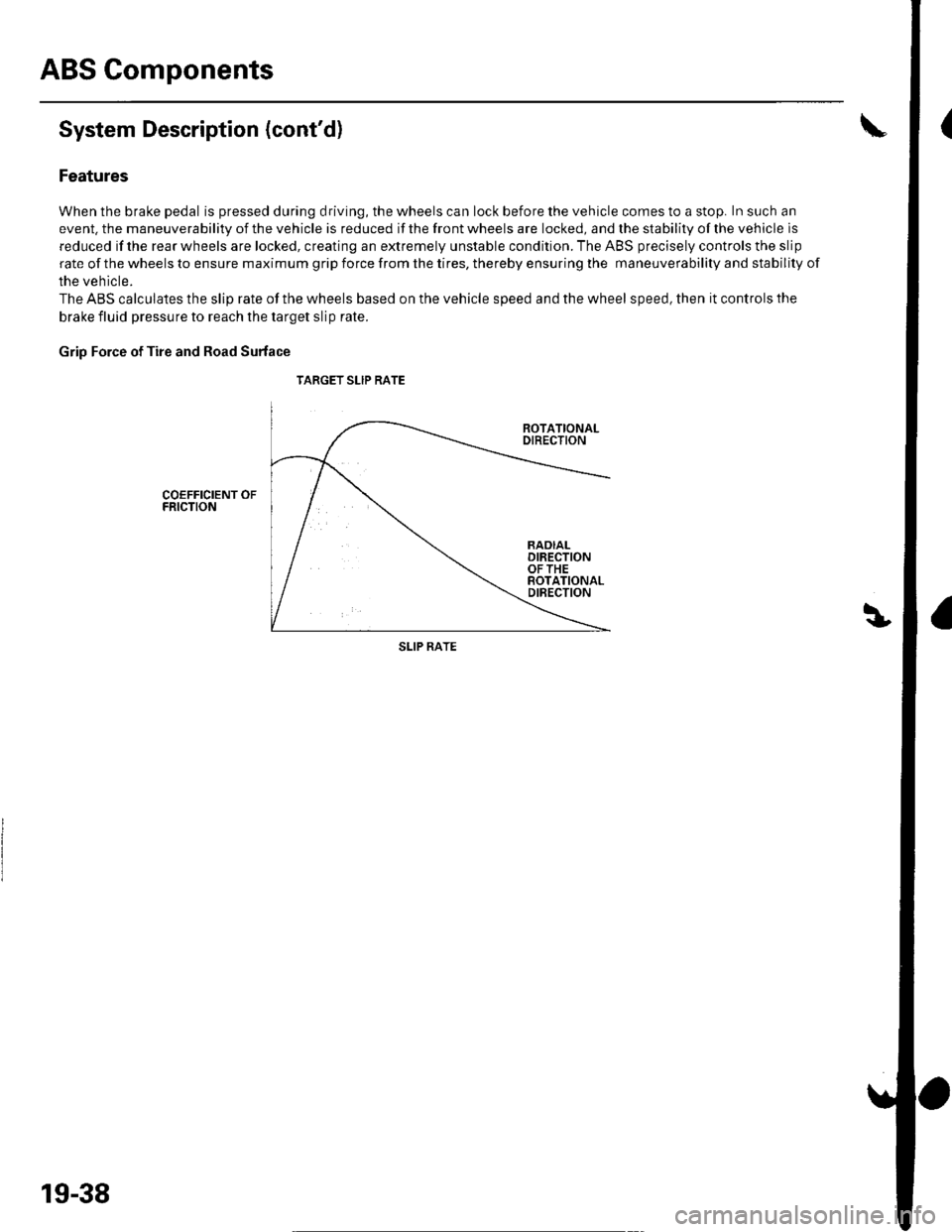
When the brake pedal is pressed during driving, the wheels can lock before the vehicle comes to a stop. In such an
event. the maneuverability of the vehicle is reduced if the front wheels are locked, and the stability of the vehicle is
reduced if the rear wheels are locked, creating an extremely unstable condition. The ABS precisely controls the slip
rate of the wheels to ensure maximum grip force from the tires, thereby ensuring the maneuverability and stability of
the vehicle.
The ABS calculates the slip rate of the wheels based on the vehicle speed and the wheel speed, then it controls the
brake fluid pressure to reach the target slip rate.
Grip Force of Tire and Road Surface
TARGET SLIP RATE
COEFFICIENT OFFRICTION
SLIP RATE
19-38
Page 634 of 1139
ABS Components
System Description (cont'd)
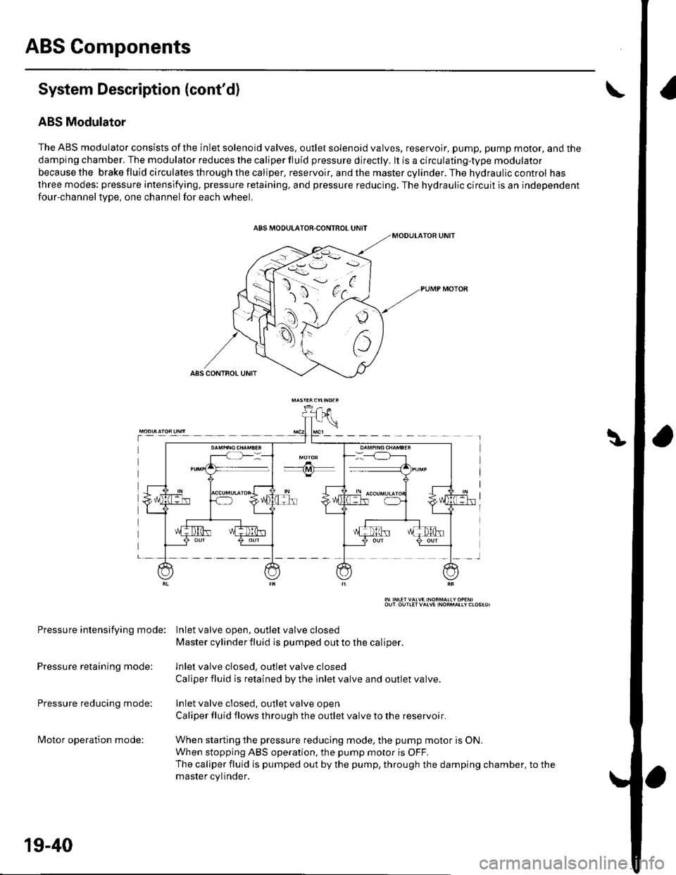
ABS Modulator
The ABS modulator consists of the inlet solenoid valves, outlet solenoid valves, reservoir, pump, pump motor, and the
damping chamber. The modulator reduces the caliper fluid pressure directly. lt is a circulating-type modulator
becausethe brakefluidcirculatesthroughthecaliper,reservoir,andthemastercylinder.Thehydrauliccontrol has
three modes: pressure intensifying, pressure retaining, and pressure reducing. The hydraulic circuit is an independent
four-channeltype, one channel for each wheel.
Pressure intensifying mode: Inletvalve open, outlel valve closed
Master cylinder fluid is pumped out to the caliper.
Pressure retaining mode: lnlet valve closed, outlet valve closed
Caliper fluid is retained by the inlet valve and outlet valve.
Pressure reducing mode: Inlet valve closed, outlet valve open
Caliper fluid flows through the outlet valve to the reservoir.
lvlotor operation mode: When starting the pressure reducing mode, the pump motor is ON.
When stopping ABS operation, the pump motor is OFF.
The caliper fluid is pumped out by the pump, through the damping chamber, to the
master cvlinder.
19-40
Page 649 of 1139
Brake System Indicator Gircuit Troubleshooting
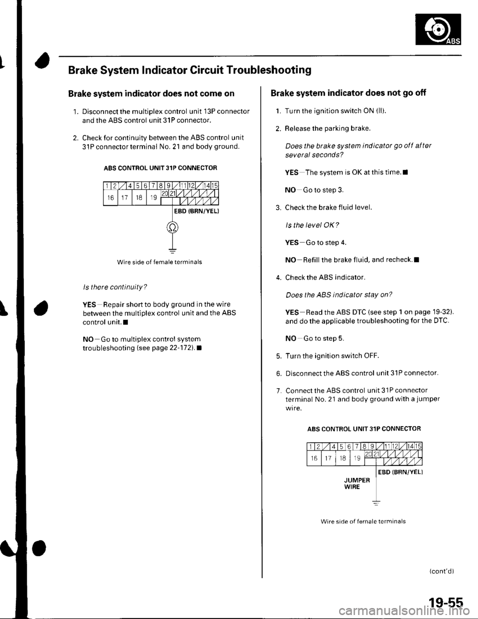
Brake system indicator does not come on
'1. Discon nect the m ultiplex contro I unit l3Pconnector
and the ABS control unit 31P connector.
2. Check for continuity between the ABS control unit
3l P connector terminal No,21 and bodyground.
ABS CONTROL UNIT 31P CONNECTOR
Wire side of female terminals
ls there continuity?
YES Repair short to body ground in the wire
between the multiplex control unit and the ABS
control unit.l
NO Go to multiplex control system
trou bleshooting lsee page 22''172).a
Brake system indicator does not go off
1. Turn the ignition switch ON {ll).
2. Release the parking brake.
Does the brake system indicatot go ofl after
several seconds?
YES The system is OK at this time.l
NO Go to step 3.
3. Check the brake fluid level.
ls the level OK?
YES Go to step 4.
NO Refill the brake fluid, and recheck.l
4. Check the ABS indicator.
Does the ABS indicator stay on?
YES Read the ABS DTC (see step 1 on page 19-32).
and do the applicable troubleshooting for the DTC
NO Go to step 5.
5. Turn the ignition switch OFF.
6. Disconnect the ABS control unit3lPconnector.
7. Connect the ABS control unit 31P connector
terminal No. 21 and body ground with a jumper
ABS CONTROL UNIT 31P CONNECTOR
(cont'd )
Wire srde of lemale lerminals
19-55
Page 651 of 1139
ABS Modulator-Control Unit Removal and lnstallation
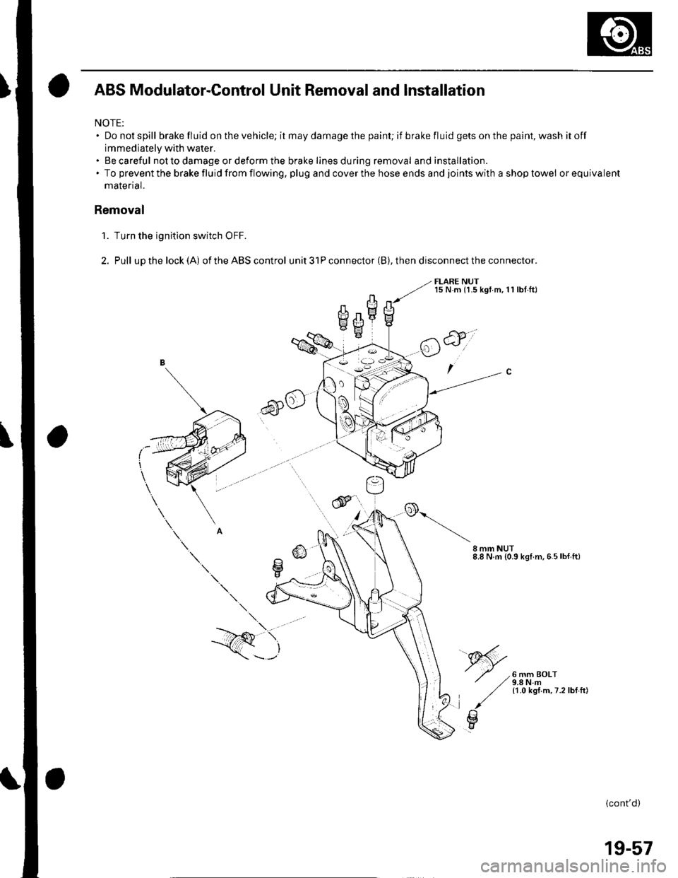
NOTE:. Donotspill brake fluid on the vehicle; it may damage the painU if brakefluidgetsonthepaint,washitoff
immediately with water.. Becareful not to damage or deform the brake lines during removal and installation.. To prevent the brake fluid from flowing, plug and cover the hose ends and joints with a shop towel orequivalent
malenal.
Removal
'1. Turn the ignition switch OFF.
2. Pull upthelock(A) oftheABScontrol unit3lPconnector(B),thendisconnecttheconnector.
FLARE NUTl5 N.m (1.5 kgt.m,11 lbt.ftl
6)o
CII mm NUT8.8 N.m {0.9 kgl m.6.5lbf ft)
6 mm BOLT9.8 N.m11.0 ksf.m,7.2lbf.ft)
\.
--/Q \,
\---'
(cont'd)
19-57
Page 851 of 1139
Connectors and Harnesses
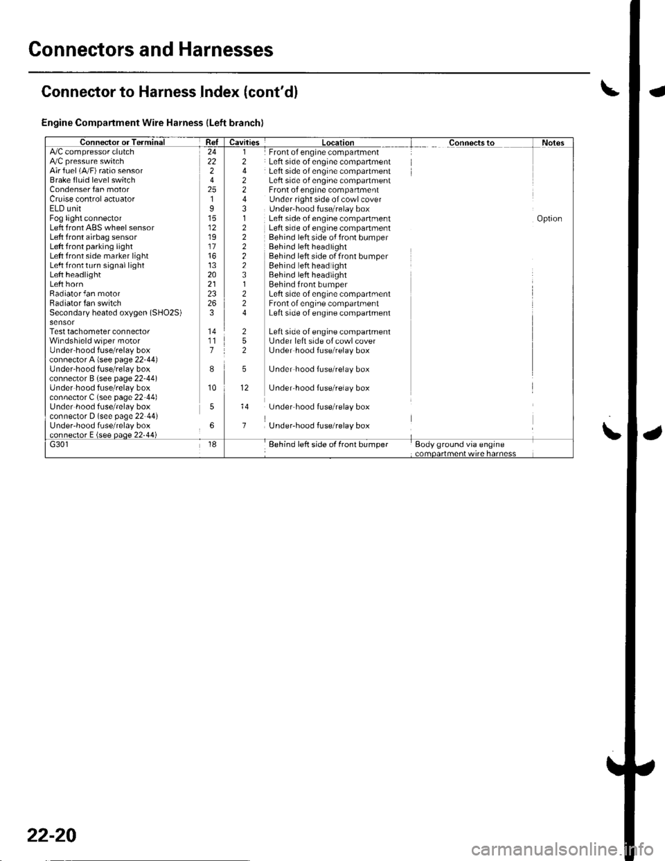
Engine Compartment Wire Harness (Left branch)
AirJuel (A,,/F) ratio sensorBrake fluid level switchCondenser fan motorCruise control actuatorELD unitFog light connectorLeft front ABS wheel sensorLeft front airbag sensorLeft front parking lightLeft front side marker lightLeft lrontturn signal lightLeft headlightLeft hornRadiator fan motorRadiator fan switchSecondary heated oxygen (SHO2S)
Test tachometer connectorWindshield wiper motorUnder'hood fuse/relay boxconnector A {see page 22-44)Under-hood f use/relay boxconnector B (see page 22-44)Under hood fuse/relay boxconnector C (see page 22-44)Under hood fuse/relay boxconnector D (see page 22 44)Under-hood fuse/relay box
Front of engine companmentLeft side of engine compartmentLeft side of engine compartmentLeft side o{ engine compartmentFront of engine compartmentUnder right side of cowl coverUnder'hood f use/relay boxLeft side of engine compartmentLeft side of engine companmentBehind left side of front bumperBehind left headlightBehind left side of front bumperEehind left headlightBehind left headlightBehind front bumperLeft side of engine compartmentFront of engine compartmentLeft side of engine compartment
Left side of engine companmentL.Jnder left side of cowl coverL.Jnder hood fuse/relay box
L.Jnder hood fuse/relay box
L.Jnder'hood f use/relay box
underhood fuse/relay box
Under-hood fuse/relay box
24222
2519
12
17
13202123
3
117
I
10
5
6
l2
2243,l
222223l224
252
5
12
Connector to Harness Index (cont'dl
\
22-20
Page 879 of 1139
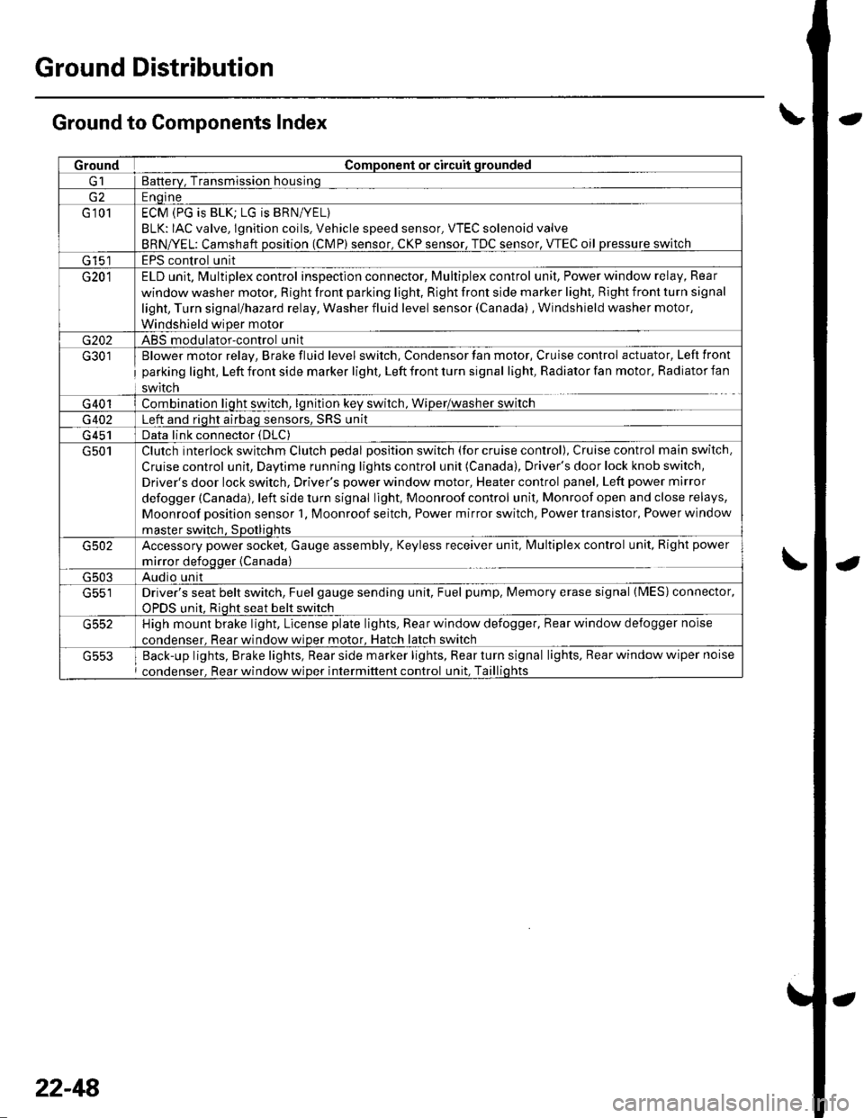
Ground Distribution
Ground to Components Index
GroundComponent or circuit qrounded
Batterv, Transmission housinq
E ngine
G 101ECM (PG is BLK; LG is BRN/YEL)
BLK: IAC valve, lgnition coils, Vehicle speed sensor, VTEC solenoid valve
BRNA/EL: Camshaft oosition (CMP) sensor. CKP sensor, TDC sensor. VTEC oil pressure switch
G 15'�]EPS control unit
G201ELD unit. Multiplex control inspection connector, Multiplex control unit, Power window relay, Rear
window washer motor, Right front parking light, Right front side marker light, Right front turn signal
light, Turn signal/hazard relay, Washer fluid level sensor (Canada) , Windshield washer motor,
Windshield wiDer motor
G202ABS modulator-control unit
G301
G401
Blower motor relay, Brake fluid level switch, Condensor fan motor, Cruise control actuator, Left front
parking light, Left front side marker light, Left front turn signal light, Radiator fan motor, Radiator fan
swrtcn
Combination liqht switch, lqnitlon kev srvitch, Wiper/wasfrer sr,virch
G402Left and riqht airbaq sensors, SRS unit
G 451Data link connector (DLC)
G501Clutch interlock switchm Clutch pedal position switch (for cruise control), Cruise control main switch,
Cruise control unit, Daytime running lights control unit (Canada), Driver's door lock knob switch,
Driver's door lock switch, Driver's power window motor, Heater control panel, Left power mirror
defogger (Canada), left side turn signal light, Moonroof control unit, Monroof open and close relays,
Moonroof position sensor '1, Moonroof seitch, Power mirror switch, Power transistor, Power window
master switch. SDotliqhts
G502Accessory power socket, Gauge assembly, Keyless receiver unit, lvlultiplex control unit, Right power
mirror defogger {Canada)
G503Audio unit
G551Driver's seat belt switch, Fuel gauge sending unit, Fuel pump, Memory erase signal (IMES) connector,
OPDS unit. Rioht seat belt switch
G552High mount brake light, License plate lights, Rear window defogger, Rear window defogger noise
condenser. Rear window wioer motor, Hatch latch switch
Back-up lights, Brake lights, Rear side marker lights, Rear turn signal lights, Rear window wiper noise
condenser, Rear window wiper intermittent control unit, Taillights
22-48
Page 885 of 1139
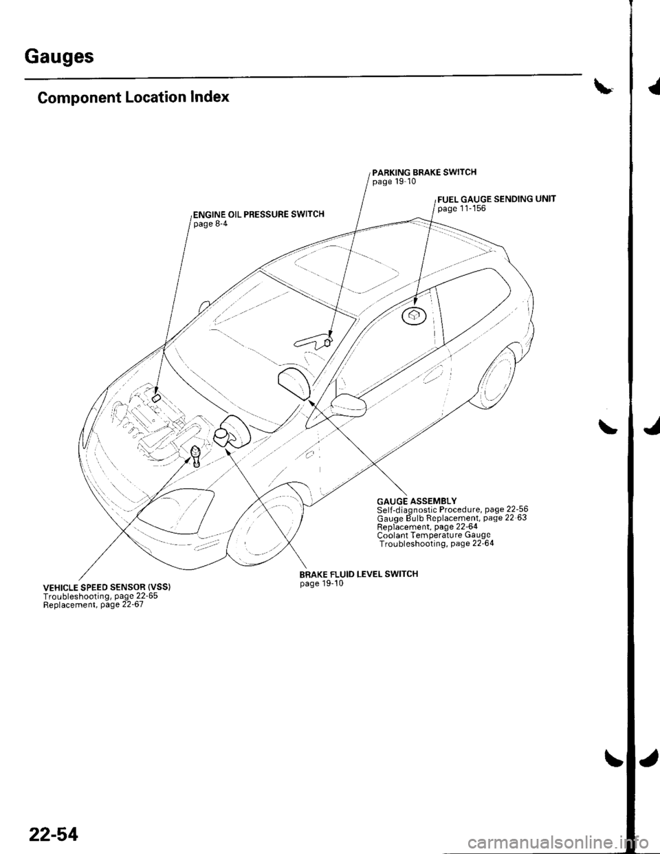
Gauges
\-Component Location Index
PARKING BRAKE SWITCHpage 19-10
FUEL GAUGE SENDINGpage 11-156ENGINE OIL PRESSURE SWITCHpage 8-4
GAUGE ASSEMBLYSelJ-diaqnostic Procedure, page 22-56Gauqe dulb Replacement, page 22 63Rep6cement, page 22-64Coolant Temperature GaugeTroLrbleshooting, page 22'64
BRAKE FLUID LEVEL SWITCHpage 19-10VEHICLE SPEED SENSOR {VSS)Troubleshooting, page 22-65Beplacement, page 22-67
22-54
\