wheel bolts HONDA CIVIC 2003 7.G Owner's Manual
[x] Cancel search | Manufacturer: HONDA, Model Year: 2003, Model line: CIVIC, Model: HONDA CIVIC 2003 7.GPages: 1139, PDF Size: 28.19 MB
Page 588 of 1139
Rear Suspension
1.
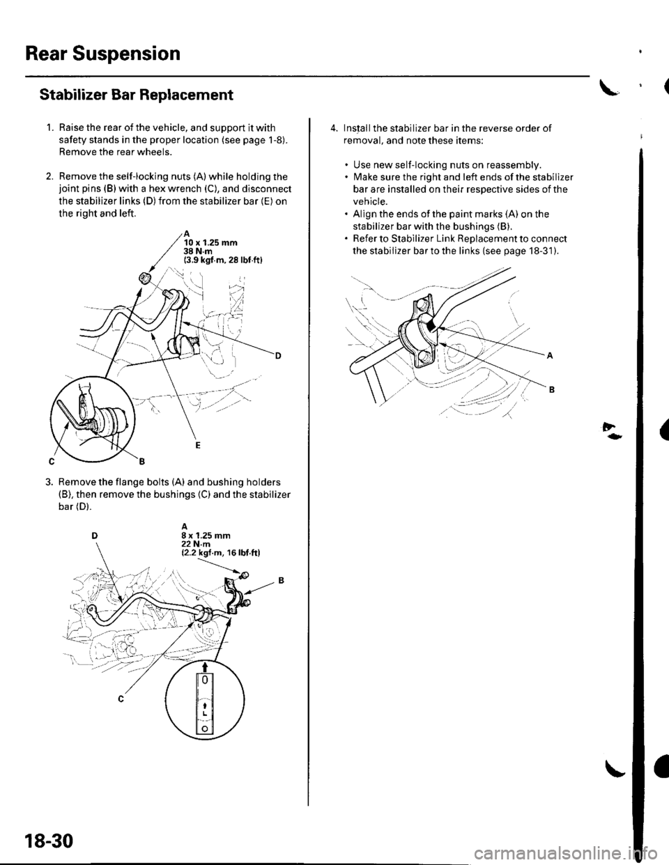
Stabilizer Bar Replacement
Raise the rear of the vehicle, and support it with
safety stands in the proper location (see page 1-8).
Remove the rear wheels.
Remove the self-locking nuts (A) while holding thejoint pins (B) with a hex wrench (C), and disconnect
the stabilizer links (D) from the stabilizer bar {E) on
the right and left.
A10 x 1.25 mm38 N.m(3.9 kgf.m,28 lbf.ft)
Remove the flange bolts (A) and bushing holders(B), then remove the bushings {C) and the stabilizer
bar (D).
18-30
4. Inslallthe stabilizer bar in the reverse order of
removal, and note these items:
. Use new self-locking nuts on reassembly.. lMake sure the right and left ends of the stabilizer
bar are installed on their respective sides of the
vehicle.. Align the ends of the paint marks (A) on the
stabilizer bar with the bushings (B).
. Refer to Stabilizer Link ReDlacement to connect
the stabilizer bar to the links {see page 18-31).
Al\.... '..: .
.----'';-r'--\---r-
-tt'.,'t),
(
Page 590 of 1139
Rear Suspension
Upper Arm Removal/lnstallation
1.Raise the rear of the vehicle, and support lt with
safety stands in the proper location (see page 1-8).
Remove the rear wheels.
Place a floor jack under the trailing arm, and
support the suspensron.
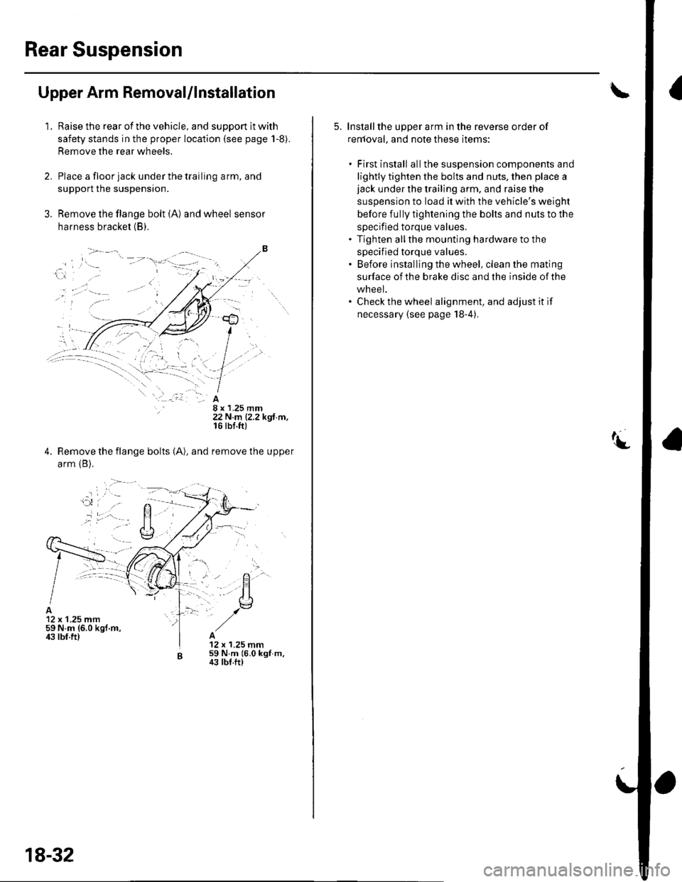
Remove the flange bolt (A) and wheel sensor
harness bracket (B).
8 x 1.25 mm22 N.m (2.2 kgf.m,16 rbf.ft)
Remove the flange bolts (A), and remove the upper
arm {B).
12 x 1.25 mm59 N.m {6.0 kgf.m,ir3 lbf.ft)12 x 1.25 mm59 N.m 16.0 kgf m,43 tbf.ft)
18-32
5. Installthe upper arm in the reverse order of
renloval, and note these items:
. First install allthe suspension components and
lightly tighten the bolts and nuts, then place ajack under the trailing arm, and raise the
suspension to load it with the vehicle's weight
before fully tightening the bolts and nuts to the
specified torque values.. Tighten allthe mounting hardware to the
specified torque values.' Before installing the wheel, clean the mating
surface of the brake disc and the inside of the
wheel.. Check the wheel alignment, and adjust it if
necessary (see page 18-4).
Page 591 of 1139
3.
Trailing Arm Removal/lnstallation
1.Raise the rear of the vehicle, and suppon it with
safety stands in the proper location (see page 1,8).
Remove the rear wheels.
Remove the knuckle (see page 18-28).
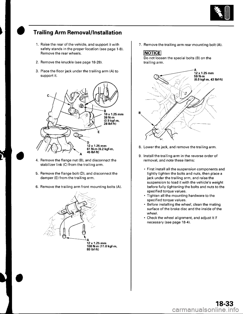
Place the floor jack under the trailing arm (A) to
support it.
B10 x 1.25 mm38Nm(3.9 kgl.m,28 tbf.ftl
12 x 1.25 mm61 N m (6.2 kgt m.
A 4s tbf,ft)
Remove the flange nut (B), and disconnect the
stabilizer link (C) from the trailing arm.
Remove the flange bolt {D), and disconnect the
damper (E) from the trailing arm.
Remove the trailing arm front mounting bolts (A).
A12 x 1.25 Jnm108 N.m {11.0 kgt.m,80 tbf.ft)
,'a':r -
7. Remove the trailing arm rear mounting bolt (A).
Do not loosen the special bolts (B) on the
trailing arm.
A12 x 1.25 mm59 N.m
-----\':,'.ttg
'.,--1..-r.':1
Lower the jack, and remove the trailing arm.
Install the trailing arm in the reverse order of
removal, and note these items:
. First install allthe suspension components and
lightly tlghten the bolts and nuts, then place ajack under the trailing arm, and raise the
suspension to load it with the vehicle's weight
before fully tightening the bolts and nuts to the
specified torque values.. Tighten allthe mounting hardware to the
specif ied torque values.. Before installing the wheel, clean the mating
surface of the brake disc and the inside of the
wneei.. Check the wheel alignment, and adjust it if
necessary (see page'18-4).
8.
9.
18-33
Page 615 of 1139
Conventional Brake Components
Rear Brake Pads Inspection and Replacement
Frequent inhalation of brake pad dust, regardless ofmaterial composition, could be hazardous to your
hea hh.. Avoid breathing dust particles.. Never use an air hose or brush to clean brake
assemblies, Use an OSHA-approved vacuum
cleaner.
Inspection
'1. Raise the rear of the vehicle, and support jt with
safety stands in the proper location (see page 1-8).Remove the rear wheels,
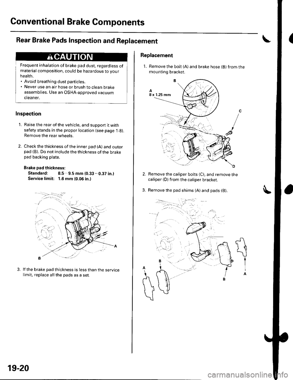
2. Check the thickness of the inner pad (A) andouterpad (B). Do not include the thickness of the brakepad backing plate.
Brake pad thickness:
Standard: 8.5 9.5 mm {0.33-0.37 in.}
Service limit: 1.6 mm (0.06 in.)
B -::--
lf the brake pad thickness is less than the servicelimit, replace allthe pads as a set.
3.
19-20
Replacement
1. Remove the bolt (A) and brake hose {B} from themounting bracket.
Remove the caliper bolts (C), and remove thecaliper (D) from the caliper bracket.
Remove the pad shims (A) and pads (B).3.
A
t{
\
tIA
A
\
r\
))
\
Page 1120 of 1139
A
\'l9
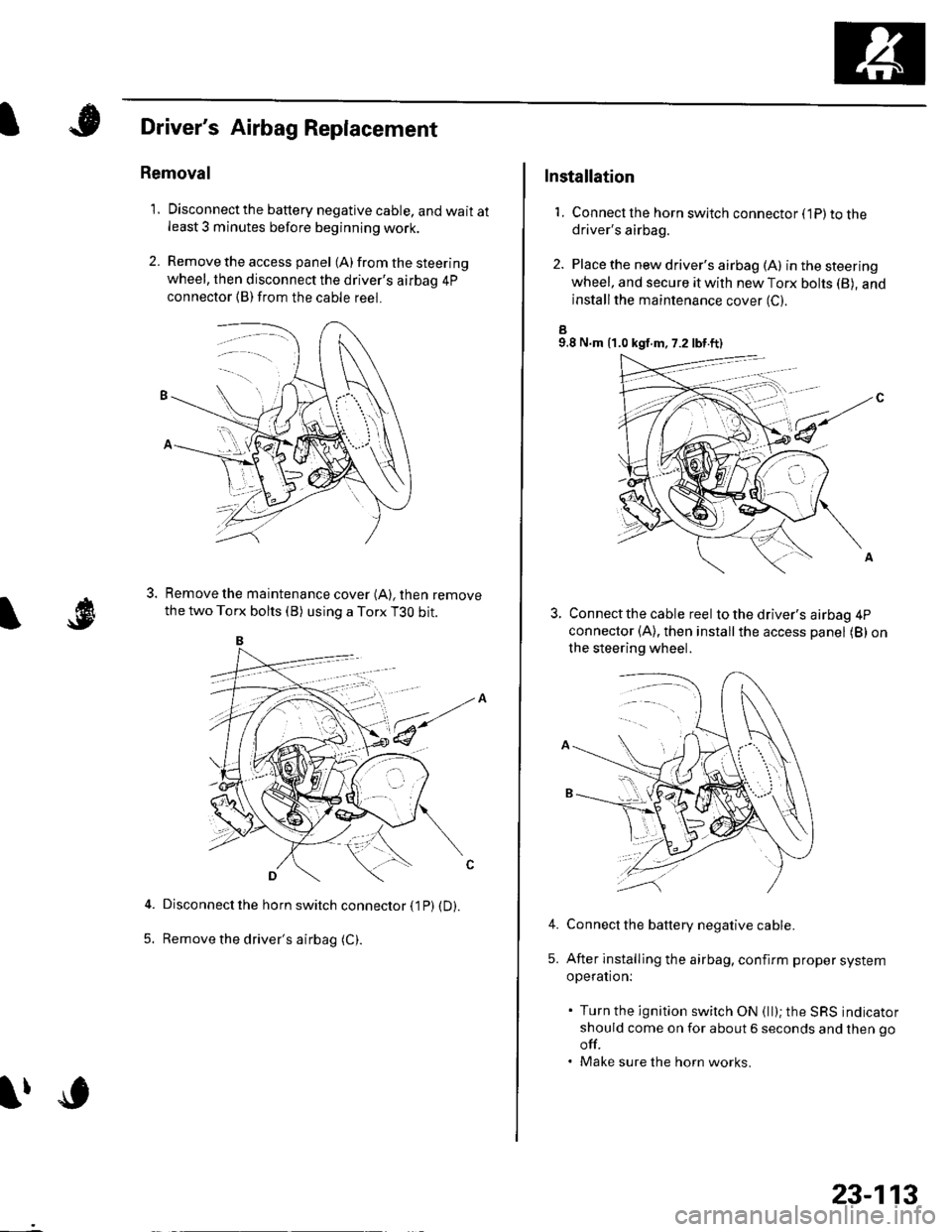
Driver's Airbag Replacement
Removal
1. Disconnectthe battery negative cable, and wait atleast 3 minutes before beginning work.
2. Remove the access panel (A) from the steering
wheel, then disconnect the driver's airbag 4p
connector (B)from the cable reel.
Remove the maintenance cover (A), then remove
the two Torx bolts (B) using a Torx T3O bit.
Disconnect the horn switch connector (1P) (D).
Remove the driver's airbag (C).5.
lfc
23-113
Installation
1. Connect lhe horn switch connector (1P) to thedriver's airbag.
2. Place the new driver's airbag (A) inthesteering
wheel, and secure it with new Torx bohs (B), and
installthe maintenance cover (C).
a9.8 N.m {1.0 kgf.m, 7.2 lbt.ft)
Connect the cable reel to the driver's airbag 4P
connector (A), then installthe access panel (B) on
the steering wheel.
Connect the battery negative cable.
After installing the airbag, confirm proper system
operation:
. Turn the ignition switch ON (ll); the SRS indicator
should come on for about 6 seconds and then go
off.. Make sure the horn works.
4.
5.