Brake system HONDA CIVIC 2003 7.G Owner's Guide
[x] Cancel search | Manufacturer: HONDA, Model Year: 2003, Model line: CIVIC, Model: HONDA CIVIC 2003 7.GPages: 1139, PDF Size: 28.19 MB
Page 631 of 1139
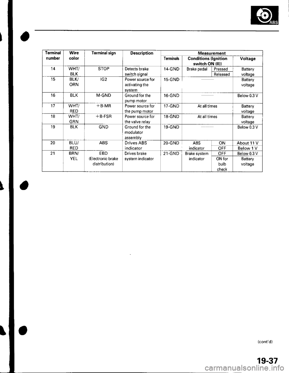
Terminal
number
Wire
color
TerminalsignDescriptionMeasurement
TerminalsConditions {lgnition
switch oN lll))
Voltage
14WHT/
BLK
STOPDetects brake
switch siqnal
I4-G NDBrake pedalPressedEattery
voltaoeReleased
t5BLV
ORN
rG2Power source for
activating the
svstem
15-GNDBaftery
voltage
16BLKM-GNDGround for the
0umD motor
16-GN DBelow 0.3 V
WHT/
RED
+ B-MRPower source for
the oumD motor
17-GNDAt alltimesBattery
voltaoe
18WHT/
GRN
+ B-FSRPower source for
the valve relav
,18-GNDAt alltimesBattery
voltaoe'19BLKGNDGround for the
modulator
assemDtv
19.GNDBelow 0.3 V
20B LU/
RED
ABSDrives ABS
indicator
20-GNDABS
indicator
ONAbout 11 V
OFFBelow 1 V
BRN/
YEL
EBD(Electronic brake
distribution)
Drives brake
system indicator
21-GNDBrake system
indicator
OFFBelow 0.3 V
ON for
bulb
cnecK
8attery
voltage
(cont'd )
19-37
Page 632 of 1139
ABS Gomponents
System Description (cont'd)
Features
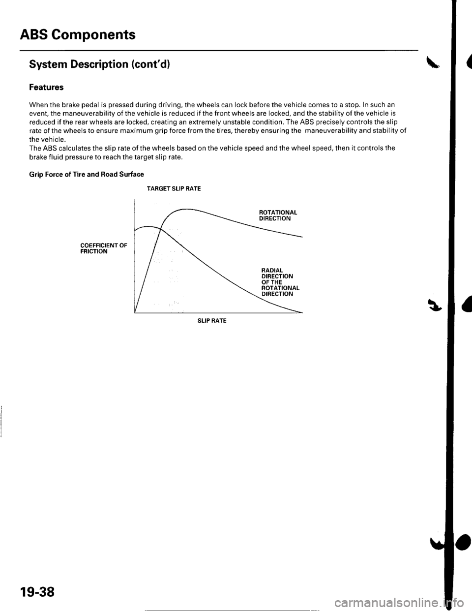
When the brake pedal is pressed during driving, the wheels can lock before the vehicle comes to a stop. In such an
event. the maneuverability of the vehicle is reduced if the front wheels are locked, and the stability of the vehicle is
reduced if the rear wheels are locked, creating an extremely unstable condition. The ABS precisely controls the slip
rate of the wheels to ensure maximum grip force from the tires, thereby ensuring the maneuverability and stability of
the vehicle.
The ABS calculates the slip rate of the wheels based on the vehicle speed and the wheel speed, then it controls the
brake fluid pressure to reach the target slip rate.
Grip Force of Tire and Road Surface
TARGET SLIP RATE
COEFFICIENT OFFRICTION
SLIP RATE
19-38
Page 634 of 1139
ABS Components
System Description (cont'd)
ABS Modulator
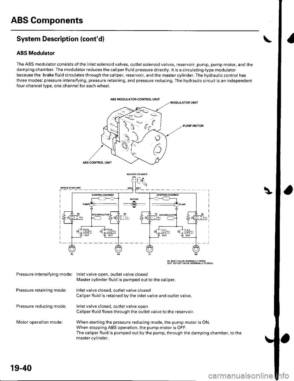
The ABS modulator consists of the inlet solenoid valves, outlet solenoid valves, reservoir, pump, pump motor, and the
damping chamber. The modulator reduces the caliper fluid pressure directly. lt is a circulating-type modulator
becausethe brakefluidcirculatesthroughthecaliper,reservoir,andthemastercylinder.Thehydrauliccontrol has
three modes: pressure intensifying, pressure retaining, and pressure reducing. The hydraulic circuit is an independent
four-channeltype, one channel for each wheel.
Pressure intensifying mode: Inletvalve open, outlel valve closed
Master cylinder fluid is pumped out to the caliper.
Pressure retaining mode: lnlet valve closed, outlet valve closed
Caliper fluid is retained by the inlet valve and outlet valve.
Pressure reducing mode: Inlet valve closed, outlet valve open
Caliper fluid flows through the outlet valve to the reservoir.
lvlotor operation mode: When starting the pressure reducing mode, the pump motor is ON.
When stopping ABS operation, the pump motor is OFF.
The caliper fluid is pumped out by the pump, through the damping chamber, to the
master cvlinder.
19-40
Page 646 of 1139
ABS Components
DTC Troubleshooting (cont'd)
DTC 81: CPU (Central Processing Unit)
1. Clear the DTC, then disconnect the Honda PGM
Tester.
2. Test-drive the vehicle.
Does the ABS indicator come on and is DTC 81
indicated ?
YES Replace the ABS modulator-control unit.l
NO-The system is OK at this time. t
19-52
ABS Indicator Gircuit
Troubleshooting
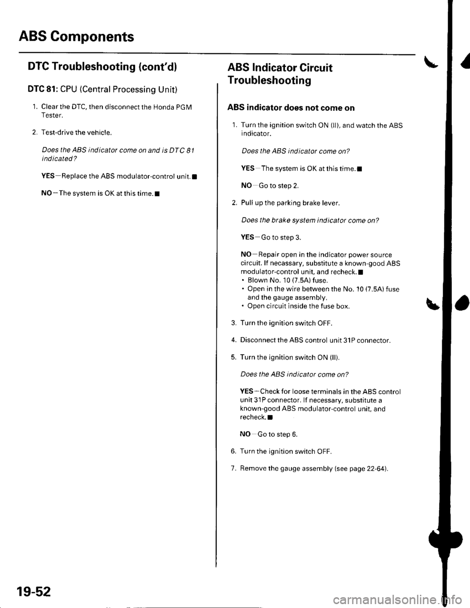
ABS indicator does not come on
1. Turn the ignition switch ON (ll), and watch the ABS
indicator.
Does the ABS indicator come on?
YES The system is OK at this time.I
NO Go to step 2,
Pull up the parking brake lever.
Does the btake system indicator come on?
YES Go to step 3.
NO Repair open in the indicator power source
circuit. lf necassary, substitute a known-good ABS
modulator-control unit, and recheck. I. Blown No, 10 (7.5A) fuse.. Open in the wire between the No. 10 (7.5A)fuse
and lhe gauge assembly,. Open circuit inside the fuse box.
Turn the ignition switch OFF.
Disconnect the ABS control unit 31P connector.
Turn the ignition switch ON (ll).
Does the ABS indicator come on?
YES-Check for loose terminals in the ABS control
unit 31P connector. lf necessary, substitute a
known-good ABS modulator-control unit, and
recheck.l
NO Go to step 6.
Turn the ignition switch OFF.
Remove the gauge assembly (see page 22-64).
3.
5.
6.
7.
Page 649 of 1139
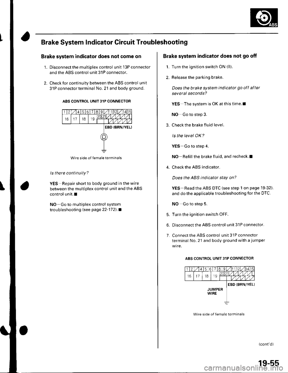
Brake System Indicator Gircuit Troubleshooting
Brake system indicator does not come on
'1. Discon nect the m ultiplex contro I unit l3Pconnector
and the ABS control unit 31P connector.
2. Check for continuity between the ABS control unit
3l P connector terminal No,21 and bodyground.
ABS CONTROL UNIT 31P CONNECTOR
Wire side of female terminals
ls there continuity?
YES Repair short to body ground in the wire
between the multiplex control unit and the ABS
control unit.l
NO Go to multiplex control system
trou bleshooting lsee page 22''172).a
Brake system indicator does not go off
1. Turn the ignition switch ON {ll).
2. Release the parking brake.
Does the brake system indicatot go ofl after
several seconds?
YES The system is OK at this time.l
NO Go to step 3.
3. Check the brake fluid level.
ls the level OK?
YES Go to step 4.
NO Refill the brake fluid, and recheck.l
4. Check the ABS indicator.
Does the ABS indicator stay on?
YES Read the ABS DTC (see step 1 on page 19-32).
and do the applicable troubleshooting for the DTC
NO Go to step 5.
5. Turn the ignition switch OFF.
6. Disconnect the ABS control unit3lPconnector.
7. Connect the ABS control unit 31P connector
terminal No. 21 and body ground with a jumper
ABS CONTROL UNIT 31P CONNECTOR
(cont'd )
Wire srde of lemale lerminals
19-55
Page 650 of 1139
ABS Components
8.
9.
10.
11.
12.
13.
Brake System Indicator Gircuit Troubleshooting (cont'd)
Turn the ignititon switch ON (ll).
Check the brake system indicator.
Does the brake system indicatot go off?
YES-Replace the ABS modulator-control unit.l
NO-Go to step 10.
Turn the ignition switch OFF.
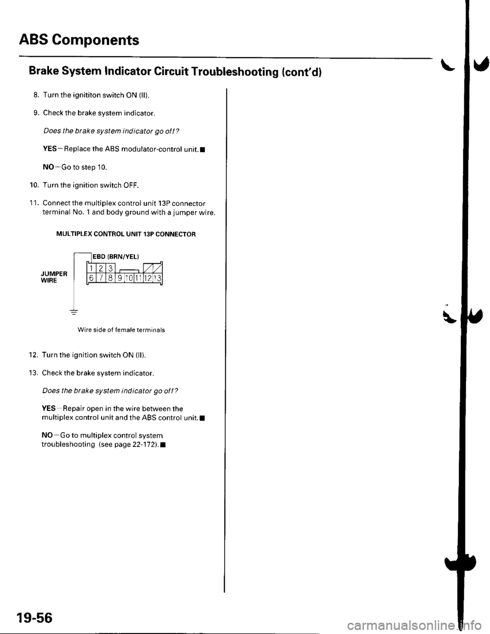
Connect the multiplex control unit 13P connector
terminal No. 'l and body ground with a jumper wire.
MULTIPLEX CONTROL UNIT 13P CONNECTOR
JUMPERWIRE
Wire side of female terminals
Turn the ignition switch ON (ll).
Check the brake system indicator.
Does the btake system indicatot go off?
YES Repair open in the wire between the
multiplex control unit and the ABS control unit.l
NO Go to multiplex control system
troubleshootin g (see page 22-17 2). a
19-56
\
Page 652 of 1139
ABS Gomponents
ABS Modulator-Control Unit Removal and Installation {cont'dl
3. Disconnectthe six brake lines.
4. Remove the two I mm nuts.
5. Remove the ABS modulator-control unit (C).
Installation
'1. InstalltheABS modulatorcontrol unit, then tighten the two 8 mm nuts.
2. Align the connecting surface ofthe ABS control unit 3'lP connector.
3. PushinthelockoftheABScontrol unit 31P connector until you hear it click into place. then connect the connector.
4. Connect the six brake Iines.
5. Bleed the brake system, starting with the front wheels.
6. Connect the PGM Tester, and do the solenoid function test for each wheel.
7. Bleed the brake system again, staning with the front wheels.
8. Start the engine, and check that the ABS indicator and brake system indicator go off.
9. Disconnect the Honda PGM Tester. Test-drive the vehicle, and check that the ABS indicator and brake qvqtem
indicator do not come on.
19-58
Page 831 of 1139
\Body Electrical
Body ElectricalSpecialToolsGeneral Troubleshooting tntorrnaiion.'......
Relay and Control Unit Locations .....
Connectors and Harnesses
Fuse/Relay Boxes ...............................
Power Distribution .............................
Ground Distribution ...........................
Under-dash Fuse/Relay Box ..............
Battery ..............
Relays ................
*lgnition Switch ..............
*Gauges
Component Location Index .......................Self-diagnostic Procedure ..........................Circuit DiagramGauge Bulb Replacement ..........................Gauge Assembly ReplacementCoolant Temperature
Gauge Troubleshooting .... ....................Vehicle Speed Signal CircuitTroubleshootingVSS Replacement
Exterior LightsComponent Location Index .......................Circuit DiagramDaytime Running Lights ControiUnit Input Test (Canada) ........................Headlight Ad,ustment .................. .. .....Headlighr Replacement ..............................Combination Light SwitchTest/ReplacementBulb ReplacementTaillight Replacement ..........................High Mount Brake Light Replacement ......License Plate Light Replacement ..............Side Marker Light Replacement ................Brake Pedal Position Switch Test ..............Side Turn Signal Light Replacement ........
Turn Signal/HazardFlasher SystemComponent Location Index .......................Circuit DiagramTurn Signal/Hazard Relay lnputTest ........Hazard Warning Switch Test
22,3
22-7
22-13
22-44
22-46
22-4A
22-49
22-50
22-51
22-53
22-5422-5622-5422 6322-64
22-64
22-6522 61
22-6822--71
22-7 622-7422-79
22-AO22-4122-8222-4222-4322-4322-4422-84
22-8�522 A622-8722-88
22-10422-105
22-10622-107
Entry Lights control systemComponent Location Index ....................... 22-89Circuit Diagram ......... 22 90lgnition Key Switch Test .....................,...... 22-9'llgnition Key Light Test ............................... 22-91Control Unit Input Test ..........,.................... 22 92
Interior LightsComponent Location Index ....................... 22-94Circuit Diagram ......... 22-95Ceiling LighVSpotlightsTesVReplacement ................................... 22-96Rear Ceiling Light TesVReplacem ent ........ 22-96Cargo Area Light Test/Replacem ent ......... 22-97Hatch Latch Switch Test ..,..,....................... 22-97
*Audio SystemComponent Location Index ....................... 22-98Circuit Diagram ......... 22,99Audio Unit Removal/lnstallation ............... 22-1OOAudio Unit Connector Replacement ......... 22-101Speaker Replacement ................................ 22-102Roof Antenna Rep1acement ....................-.. 22-103
Rear Window DefoggerComponent Location Index ...........Circuit Diasram .. ....... .. ..... ....... ...:::::.::.::.Function TestDefogger Wire Repair .................................Noise Condenser CapacityTest ................
MoonroofComponent Location Index ....................... 22-1OBCircuit Diagram ......... 22-109Moonroof Control Unit Input Test ............. 22-'l10Switch TesVReplacement ........,.....,........... 22-1 12Motor Test ................. 22-112Limit Swilch Test ...... 22-'l'13Auto-stop Switch Test ................................ 22-1 13
Power MirrorsComponent Location Index ....................... 22-114Circuit Diagram ......... 22-115Function Test ............. 22-116Power Mirror Switch Test .......................... 22-ll7Power Mirror Actuator Test ....................... 22-117Power Mirror Actuator Replacement ........ 22-11A
* HornsComponent Location Index ....................... 22-120Circuit Diagram ......... 22-121Horn TesVReplacement ...........................-. 22-122Horn Switch Test .,.... 22-122
\
Page 887 of 1139
Gauges
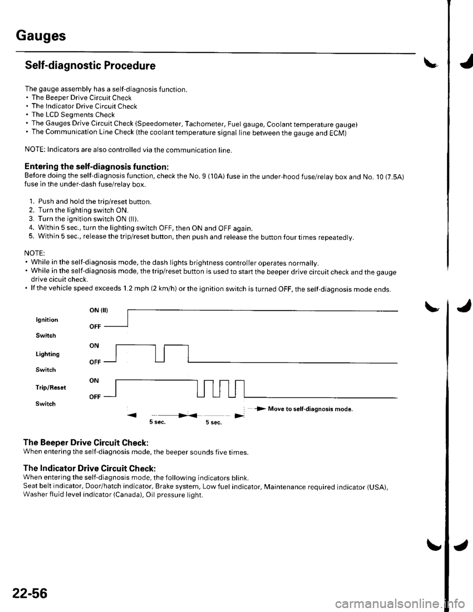
Self-diagnostic Procedure
The gauge assembly has a self-diagnosis function.. The Beeper Drive Circuit Check. The Indicator Drive Circuit ChecL. The LCD Segments Check. The Gauges Drive Circuit Check (Speedometer, Tachometer, Fuel gauge, Coolant temperature gauge). The Communication Line Check (the coolanttemperature signal line between the gauge and ECM)
NOTE: Indicators are also controlled via the communication line.
Entering the self-diagnosis f unction:
Before doing the self-diagnosis function, check the No. 9 (10A) fuse in the under-hood fuse/relay box and No. 10 {7.5A)fuse in the under'dash fuse/relay box.
1. Push and hold the trip/reset button.
2. Turn the lighting switch ON.
3. Turn the ignition switch ON (ll).
4. Within 5 sec., turn the lighting switch OFF, then ON and OFF again.5. Within 5 sec., release the trip/reset button, then push and release the button four times reDeatedlv.
NOTE:. While in the self-diagnosis mode, the dash lights brightness controller operates normally.'Whileintheself-diagnosismode,thetrip/resetbuttonisusedtostartthebeeperdrivecircuitcheckandthegauge
drive cicuit check.. lf the vehicle speed exceeds 1.2 mph 12 km/h) orthe ignition switch is tu rned OFF, the self,diag nosis mode ends.
oN flrl
lgnition
Switch
Lighting
Switch
Trip/Reset
Switch-> Move to selt-diagnosis mode.
5 sec.5 sec.
The Beeper Drive Circuit Check:
When entering the self-diagnosis mode, the beeper sounds five times
The Indicator Drive Circuit Check:
When entering the self-diagnosis mode, the following indicators blink.
Seat belt indicator, Door/hatch indicator, Brake system, Lowfuel indicator, Maintenance required indicator (USA),
Washer fluid level indicator (Canada), Oil pressure light.
v
OFF
22-56
Page 907 of 1139
Exterior Lights
Daytime Running Lights Control Unit Input Test - Canada
The DRL indicator light in the gauge assembly will come on when you turn the ignition switch to ON (ll) with the
headlight switch off and the parking brake se1. lt should go off when you turn on the headlight switch and release the
parking brake. lf it comes on at any other time, do the control unit input test.
NOTE: When the daytime running lights are on, the high beam indicator will glow at half its normal intensity.
1. Remove the driver's dashboard lower cover (see page 20-60).
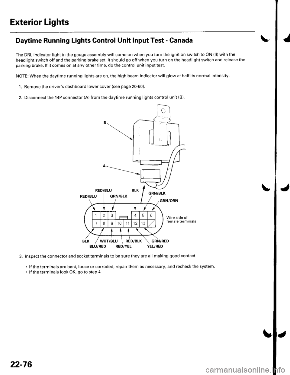
2, Disconnectthe l4Pconnector(A) from thedaytime running lightscontrol unit(B).
RED/BLUGNN/BLKRED/BLUGRN/BLKGRN/ORN
BLU/RED RED/YEL YEL/RED
Inspect the connector and socket terminals to be sure they are all making good contact.
. lf the terminals are bent, loose orcorroded, repairthem as necessary, and recheckthe system.
' lf the terminals look OK, go to step 4.
\
22-76