Brake system HONDA CIVIC 2003 7.G User Guide
[x] Cancel search | Manufacturer: HONDA, Model Year: 2003, Model line: CIVIC, Model: HONDA CIVIC 2003 7.GPages: 1139, PDF Size: 28.19 MB
Page 217 of 1139
Fuel and Emissions Systems
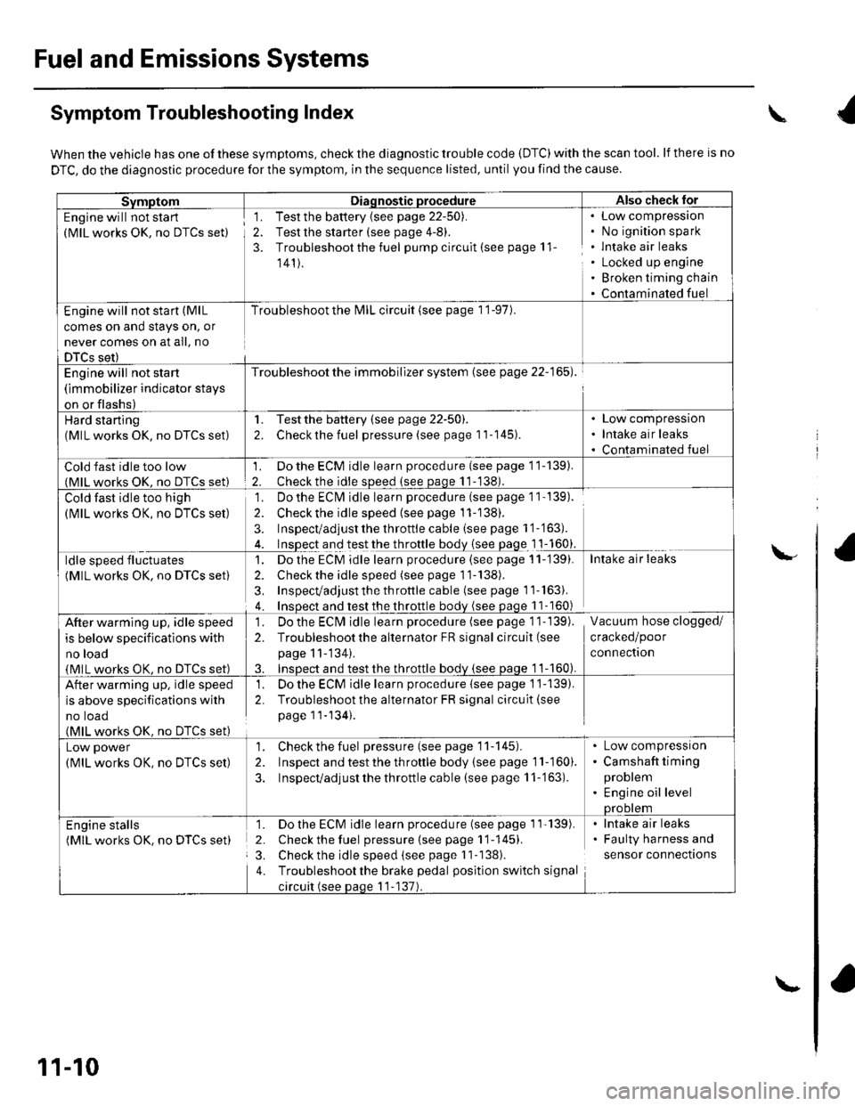
Symptom Troubleshooting Index
When the vehicle has one of these symptoms, check the diagnostic trouble code (DTC) with the scan tool. lf there is no
DTC, do the diagnostic procedure for the symptom, in the sequence listed, until you find the cause.
SvmotomDiaqnostic procedureAlso check lor
Engine will not sta rt
(MlL works OK, no DTCS set)
1. Test the battery {see page 22-50).
2. Test the starter (see page 4-8).
3. Troubleshoot the fuel pump circult (see page 11
141).
Low compressron
No ignition spark
lntake air leaks
Locked up engine
Broken timing chain
Contaminated fuel
Engine will not start (MlL
comes on and stays on, or
never comes on at all, no
DTCS set)
Troubleshoot the l\4lL circuit (see page 1 '1-97).
Engine will not start
(immobilizer indicator stays
on or flashs)
Troubleshoot the immobilizer system (see page 22-165).
Hard starting(MlL works OK, no DTCS set)
1. Testthe battery (see page 22-50).
2. Checkthe fuel pressure (see page 11-145).
Low compression
Intake air leaks
Contaminated fuel
Cold fast idle too low(MlL works OK. no DTCS set)
1. Do the ECM idle learn procedure (see page 11-139).
2. Checkthe idle sDeed (see paqe 11-138).
Cold fast idle too high
(MlL works OK, no DTCS set)
Do the ECI\4 idle learn procedure (see page 1 1- 139).
Checkthe idle speed {see page 11-138).
Inspect/adjust the throttle cable (see page 1 '1-'163).
Inspect and test the throttle body {see page 1 1-160}.
']�
2.
3.
ldle speed fluctuates
(MlL works OK, no DTCS set)
1. Dothe ECM idle learn procedure (see page 11-'139).
2. Check the idle speed (see page 11-138).
3, Inspecvadjust th e throttle cable (see page 11''163).
4. Insoect and test the throttle bodv (see paqe 11- 160)
Intake air leaks
After warming up, idle speed
is below specifications with
no load
{MlL works OK, no DTCS set)
1. Do the ECIVI idle learn procedure (see page 1 1- 139).
2. Troubleshootthe alternator FR signal circuit (see
page 11-'134).
3. InsDect and test the throttle bodv {see paqe 1 1-160).
Vacuum hose clogged/
cracked/poor
connectron
After warming up, idle speed
is above specifications with
no toao(MlL works OK. no DTCS set)
1. Do the ECM idle learn procedure {see page 1'j-139).
2. Troubleshoot the alternator FR signal circuit(see
page 11-134).
Low power
(MlL works OK, no DTCS set)
1. Check the fuel pressure(seepagell-145).
2. Inspect and test the th roftle body (see page 11-160).
3. Inspecvadjust the throttle cable (see page 11-'163).
Low compressron
Camshaft timing
problem
Engine oil levelprootem
Engine stalls(MlL works OK. no DTCS set)
1. Do the ECM idle learn procedure (see page 1'l'139).
2. Check the fuel pressure{seepagell-145).
3. Check the idle speed (see page I 1-138).
4. Troubleshootthe brake pedal position switch signal
circuit (see paqe 11-137).
lntake air leaks
Faulty harness and
sensor connections
\
\-
11-10
\-
Page 239 of 1139
Fuel and Emissions Systems
(
{
System Descriptions (cont'd)
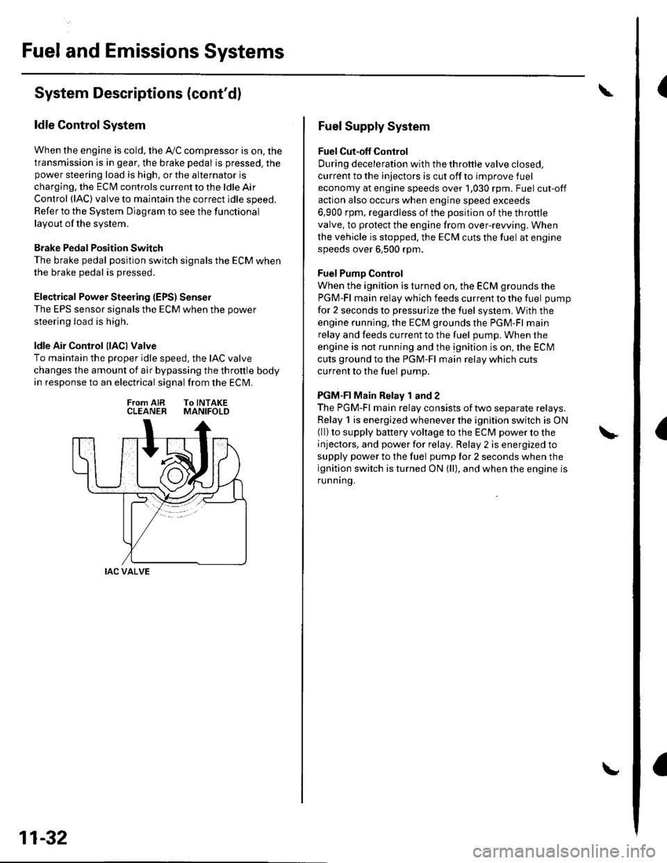
ldle Control System
When the engine is cold, the Ay'C compressor is on, the
transmission is in gear, the brake pedal is pressed. thepower steering load is high, or the alternator is
charging, the ECIM controls current to the ldle Air
Control (lAC) valve to maintain the correct idle speed.
Refer to the System Diagram to see the functional
layout of the system.
Brake Pedal Position Switch
The brake pedal position switch signals the ECM when
the brake pedal is oressed.
Electrical Power Steering (EPS) Senser
The EPS sensor signals the ECM when the power
steering load is high.
ldle Air Control llACl Valve
To maintain the proper idle speed, the IAC valve
changes the amount of air bypassing the throttle body
in response to an electrical signal from the ECM.
From AIR To INTAKECLEANER MANIFOLD
IAC VALVE
11-32
Fuel Supply System
Fuel Cut-off Control
During deceleration with the throttle valve closed,
current to the injectors is cut off to improve fuel
economy at engine speeds over 1,030 rpm. Fuel cut-off
action also occurs when engine speed exceeds
6,900 rpm, regardless of the position of the throttle
valve, to protect the engine from over-rewing. When
the vehicle is stopped. the ECM cuts the fuel at engine
speeds over 6,500 rpm.
Fuel Pump Control
When the ignition is turned on, the ECM grounds the
PGM-Fl main relay which feeds current to the fuel pump
for 2 seconds to pressurize the fuel system, With the
engine running. the ECM grounds the PGM-Fl main
relay and feeds current to the fuel pump. When the
engine is not running and the ignition is on, the ECI\4
cuts ground to the PGM-Fl main relay which cuts
current to the fuel pump.
PGM-FI Main Relay 1 and 2
The PGM-Fl main relay consists of two separate relays.
Relay 1 is energized whenever the ignition switch is ON(ll) to supply battery voltage to the ECM power to the
injectors, and power for relay, Relay 2 is energized to
supply power to the fuel pump for 2 seconds when the
ignition switch is turned ON (ll), and when the engine is
runnrng.
Page 287 of 1139
PGM-Fl System
6.
1.
DTC Troubleshooting (cont'dl
DTC P0500: VSS Circuit Malfunction
1. Test-drive the vehicle.
2. Check the vehicle speed with the scan tool.
ls the correct speed indicated?
YES-lntermiftent failure, system is OK at this time.
Check for poor connections or loose terminals at
the VSS and at the ECM.I
NO Go to step 3.
3. Turn the ignition switch OFF.
4. Block the rear wheels, and set the parking brake.
5. Raise the front ofthe vehicle, and make sure it is
securely supported,
Turn the ignition switch ON (ll).
Block the right front wheel, and slowly rotate the
left front wheel.
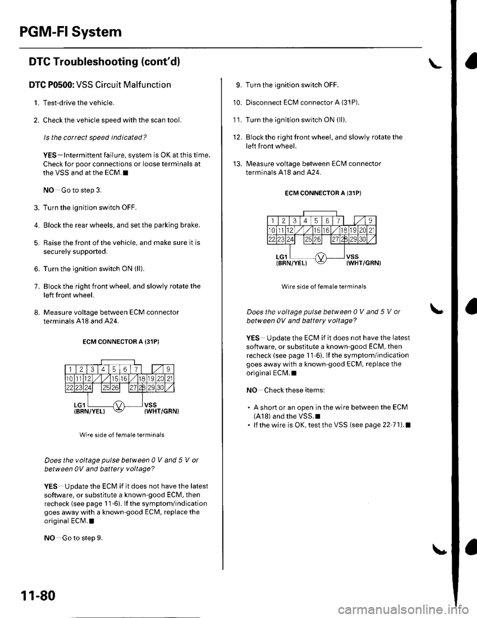
8. Measure voltage between ECM connector
terminals A18 and A24.
ECM CONNECTOR A {31P)
Wire side of female terminals
Does the voltage pulse between 0 V and 5 V or
between 0V and battery voltage?
YES-Update the ECM if it does not have the latest
software, or substitute a known-good ECM. then
recheck (see page 1 1-6). lf the symptom/indication
goes away with a known-good ECM, replace the
original ECN4.l
NO Go to step 9.
11-80
9. Turn the ignition switch OFF.
10. Disconnect ECM connector A (3'1P).
1 1. Turn the ignition switch ON {ll}.
12. Blockthe right front wheel. and slowly rotate the
left front wheel.
'!3. lMeasure voltage between ECM connector
terminals A18 and A24.
ECM CONNECTOR A I31PI
Wire side of female terminals
Does the voltage pulse between 0 V and 5 V ol
between 0V and battety voltage?
YES Update the ECM if it does not have the latest
software, or substitute a known-good ECM, then
recheck (see page 1 1-6). lf the symptom/indication
goes away with a known-good ECM, replace the
origlnal ECM.I
NO Check these items:
. A short or an open in the wire between the ECM
(A18) and the VSS.I. lf thewire is OK,testtheVSS (see page 22 71).1
Page 345 of 1139
ldle Control System
ldle Speed lnspection
NOTE:' Leave the idle air control (lAC) valve connecled.. Before checking the idle speed, check these items:- The malfunction indicator lamp (MlL) has not been
reported on.- lgnition timing- Spark plugs- Air cleaner- PCV system. Pullthe parking brake lever up. Start the engine, and
make sure the headlights are off.
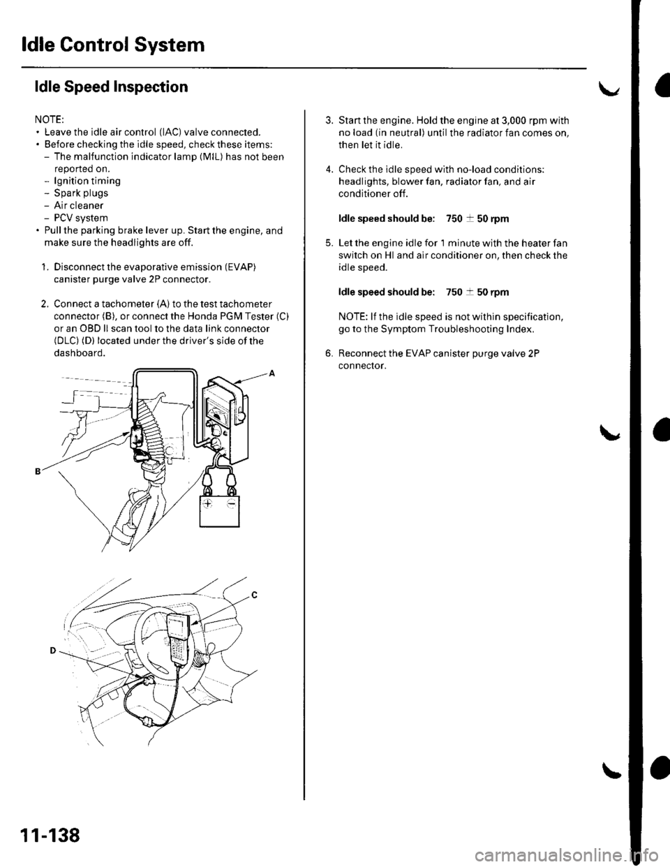
1. Disconnect the evaporative emission (EVAP)
canister purge valve 2P connector.
2. Connect a tachometer (A)to the test tachometer
connector (B), or connect the Honda PGM Tester (C)
or an OBD ll scan tool to the data link connector(DLC) (D) located under the driver's side of the
dashboard.
11-138
4.
3.
5.
6.
Start the engine. Hold the engine at 3,000 rpm with
no load (in neutral) until the radiator fan comes on,
then let it idle.
Check the idle speed with no-load conditions;
headlights, blower fan, radiator fan, and air
conditioner off.
ldle speed should be: 750 t 50 rpm
Let the engine idle for 1 minute with the heater fan
switch on Hl and air conditioner on, then check the
idle speed.
ldle speed should be: 750 t 50 rpm
NOTE: lf the idle speed is not wilhin specification,
go to the Symptom Troubleshooting Index,
Reconnect the EVAP canister purge valve 2P
connector.
Page 375 of 1139
PCV System
DTC Troubleshooting
DTC P1505: PCV Air Leakage
1. Reset the ECM (see page 11-4).
2. Start the engine. Hold the engine at 3,000 rpm with
no load (in neutral) until the radiator fan comes on
3. Let the engine idle tor al least 40 seconds with the
throttle fully closed.
4. Check for a DTC P1505 with the scan tool
ls DTC P1505 indicated?
YES-Check these parts for vacuum leaks l
. PCV valve. PCV hose. EVAP canister purge valve
. Throttle body. Brake booster hose
NO - Intermittent failure, system is OK at this
time.l
11-168
Page 405 of 1139
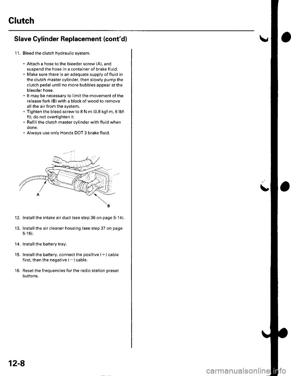
Clutch
Slave Cylinder Replacement (cont'd)
11. Bleed the clutch hydraulic system.
. Aftach a hose to the bleeder screw (A), and
suspend the hose in a container of brake fluid.. Make sure there is an adequate supply offluid in
the clutch master cylinder, then slowly pump the
clutch pedal until no more bubbles appear atthe
bleeder hose.. lt may be necessary to llmit the movement of the
release fork (B) with a block of wood to remove
all the air from the system.. Tighten the bleed screw to I N.m (0.8 kgf.m, 6 lbf
ft); do not ovenighten it,. Refill the clutch master cylinder with fluid when
done.. Always use only Honda DOT 3 brake fluid.
Install the intake air duct (see step 36 on page 5-14).
Installthe air cleaner housing (see step 37 on page
5-15).
Install the battery tray.
Install the battery, connect the positive (+) cable
first, then the negative (- ) cable.
Reset the frequencies for the radio station preset
buttons,
12.
13.
14.
t5.
16.
12-8
L
Page 538 of 1139
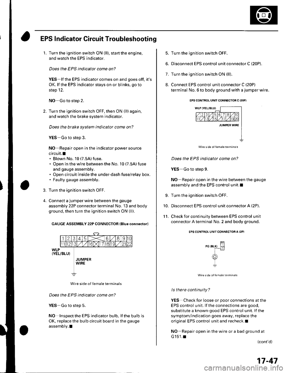
EPS Indicator Circuit Troubleshooting
1.Turn the ignition switch ON (ll), start the engine,
and watch the EPS indicator.
Does the EPS indicator come on?
YES lf the EPS indicator comes on and goes off, it's
OK. lf the EPS indicator stays on or blinks. go to
step 12.
NO Go to step 2.
Turn the ignition switch OFF, then ON (ll) again,
and watch the brake system indicator,
Does the brake system indicator come on?
YES-Go to step 3.
NO Repair open in the indicator power source
circuit.l. Blown No. 10 (7.5A)fuse.
. Open in the wire between the No. 10 (7.5A) fuse
and gauge assembly.. Open circuit inside the under-dash fuse/relay box,. Faulty gauge assembly.
Turn the ignition switch OFF,
Connect a jumper wire between the gauge
assembly 22P connector terminal No. 13 and body
ground, then turn the ignition switch ON (ll).
GAUGE ASSEMBLY 22P CONNECTOR (Blue connector)
Wire side of female terminals
Does the EPS indicator come on?
YES-Go to step 5.
NO Inspect the EPS indicator bulb, if the bulb is
OK, replace the bulb circuit board in the gauge
assembly.l
3.
4.
5. Turn the ignition switch OFF.
6. Disconnect EPS control u n it connector C (20P).
7. Turn the ignition switch ON (ll).
8. Connect EPS control unit connector C (20P)
terminal No. 6 to body ground with a jumper wire.
Wire s d€ oflemale16rmina s
Does the EPS indicatot come on?
YES Go to step 9.
NO Repair open in the wire between the gauge
assembly and the EPS control unit.l
Turn the ignition switch OFF.
Disconnect EPS control unit connector A (2P),
Check for continuity between EPS control unit
connector A terminal No. 2 and body ground.
EPS CONTROL UNITCONNECTOA A I2PI
wire s de oftemale terminals
ls there continuity?
YES Check for loose or poor connections at the
EPS control unit. lf the connections are good,
substitute a known-good EPS control unit. lf the
symptom/indication goes away, replace the
original EPS control unit and recheck.I
NO Repair open in the wire or a bad ground at
G151,t(cont'd)
9.
10.
'l 1.
EPS CONTBOL UNIT CONNECTOB C {2OP)
17-47
Page 596 of 1139
Brakes
Conventional Brake Components
Special Tools ... ..... ... l9-2
Component Location Index ......................................... 19-3
Brake System Inspection and
Tests ............... .......... 19-4
Brake Pedal and Brake Pedal Position Switch
Adjustment .............. 19-6
Parking Brake Check and
Adjustment .............. 19-7
Brake System Bleeding ...................... 19-8
Brake System Indicator Circuit
Diagram ................... 19-9
Parking Brake Switch Test ................. 19-10
Brake Fluid Level Switch Test ...................................... 19-10
Front Brake Pads lnsoection and
Replacement ........... 19-11
Front Brake Disc Inspection ............... 19-13
Front Brake Calioer Overhaul ...................................... 19-14
Master Cylinder Replacement ........... 19-15
Master Cylinder Inspection ................ 19-16
Brake Booster
Pushrod Clearance Adjustment ................................ 19-16
Brake BoosterTest ................... .......... 19-18
Brake Booster Reolacement .............. 19-19
Rear Brake Pads Inspection and
Reolacement ........... 19-20
Rear Brake Disc Inspection ................ 19-22
Rear Brake Caliper Overhaul ....................................... 19-23
Brake Hoses and Lines Insoection .... 19-24
Brake Hose Reolacement ................... 19-25
Parking Brake Cable Replacement .............................. 19-26
ABS (Anti-lock Brake System)
Gomponents ... 19-29
Page 598 of 1139
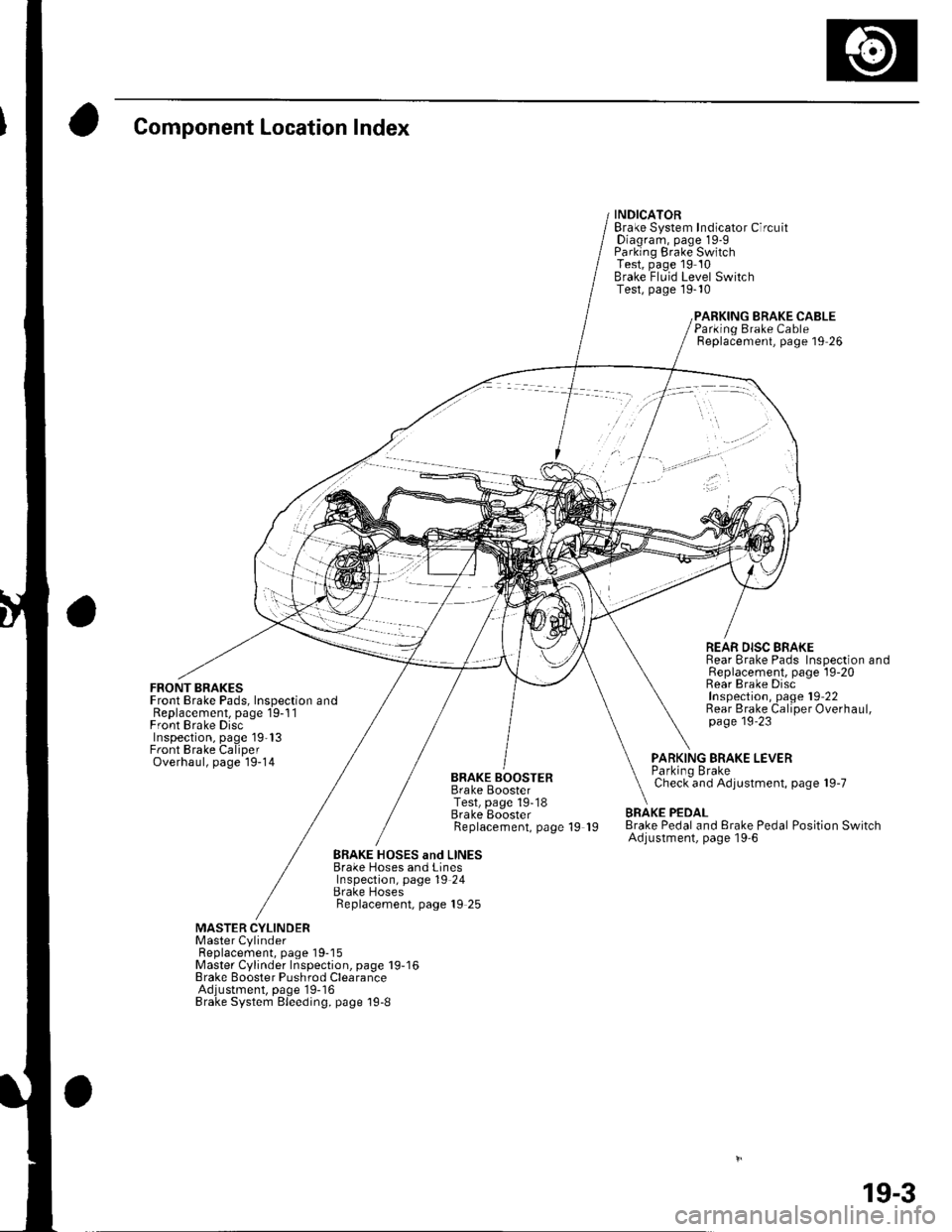
Component Location Index
FRONT BRAKESFront Brake Pads, Inspection andReplacement, page 19-1 1Front Brake DiscInspection, page 19'13Front Brake CaliperOverhaul, page 19-14
INDICATORBrake System Indicator CircuitDiagram, page 19-9Parking Brake SwitchTest, page 19 10Brake Fluid Level SwitchTest, page 19-10
BRAKE CABLE
BRAKE BOOSTERBrake BoosterTest, page 19-18Brake EoosterReplacement, page 19 19
Parking Brake CableReplacement, page 19 26
REAR DISC BRAKERear Brake Pads Inspection andReplacement, page l9-20Rear Brake DiscInspection, page 19'22Rear Brake Caliper Overhaul,page 19'23
PARKING BRAKE LEVERParkino BrakeCheck and Adjustment, page 19-7
BRAKE PEDALBrake Pedal and Erake Pedal Position SwitchAdjustment, page l9-6
BRAKE HOSES and LINESBrake Hoses and LinesInspection, page 19 24Brake HosesReplacement, page 19 25
MASTER CYLINDERMaster CylinderFl6^1.^6m6nr ^2^o 1O-18Master Cylinder Inspection, page 19-16Brake Booster Pushrod ClearanceAdjustment, page'19-16Brake System Bleeding, page 19-8
19-3
Page 599 of 1139
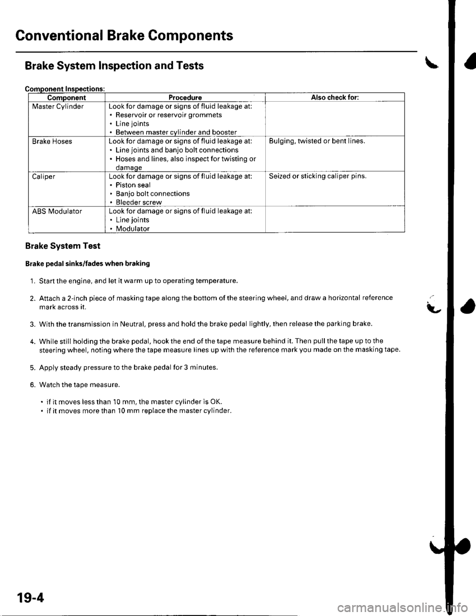
Gonventional Brake Components
ComponentProcedureAlso check for:
l\4aster CylinderLook for damage or signs of fluid leakage at;. Reservoir or reservoir grommets
. Line joints
. Between master cvlinder and booster
Brake HosesLook for damage or signs of fluid leakage at:. Line joints and banjo bolt connections. Hoses and lines. also inspect for twisting or
damaqe
Bulging, twisted or bent lines.
CaliperLook for damage or signs of fluid leakage at:. Piston seal. Banjo bolt connections. Bleeder screw
Seized or sticking caliper pins.
ABS l\ilodulatorLook for damage or signs of fluid leakage at:. Line joints
. Modulator
Brake System Inspection and Tests
Brake System Test
Brake pedal sinks/fades when braking
1. Start the engine, and let it warm up to operating temperature.
2. Attach a 2-inch pieceof masking tape along the bottom of the steering wheel, and draw a horizontal reference
mark across it.
With the transmission in Neutral, press and hold the brake pedal lightly, then release the parking brake.
While still holding the brake pedal, hook the end of the tape measure behind it. Then pull the tape up to the
steering wheel, noting where the tape measure lines up with the reference mark you made on the masking tape.
Apply steady pressure to the brake pedal for 3 minutes.
Watch the tape measure.
. if it moves less than 10 mm, the master cylinder is OK.
. if it moves more than 10 mm replace the master cylinder.
t-
3.
5.
6.
19-4