connector HONDA CIVIC 2003 7.G Service Manual
[x] Cancel search | Manufacturer: HONDA, Model Year: 2003, Model line: CIVIC, Model: HONDA CIVIC 2003 7.GPages: 1139, PDF Size: 28.19 MB
Page 212 of 1139
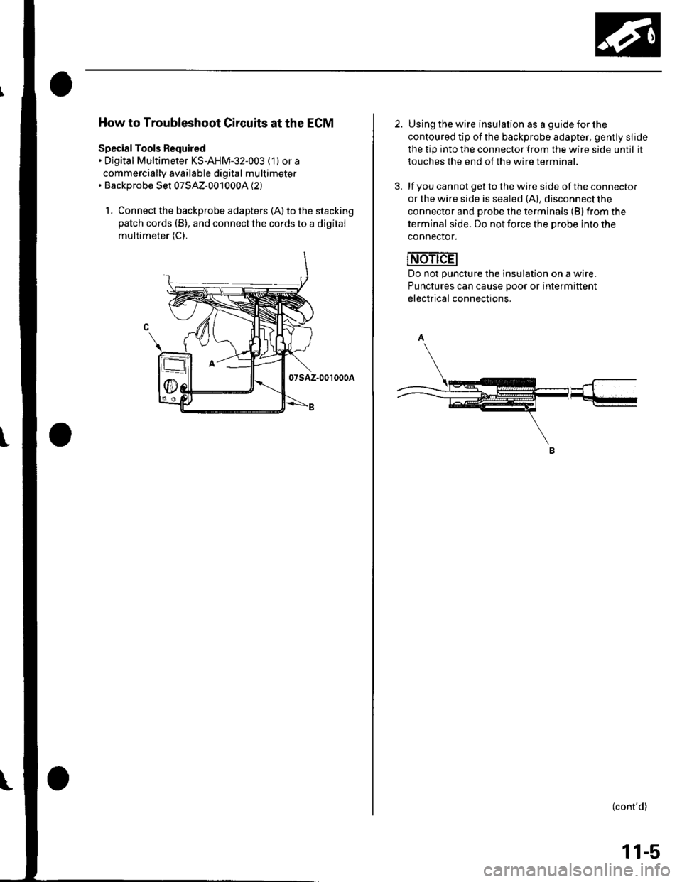
How to Troubleshoot Circuits at the ECM
Special Tools Required. Digital Multimeter KS-AHM-32-003 (1) or a
commercially available digital multimeter. Backprobe Set 07SAZ-0010004 (2)
1. Connect the backprobe adapters (A) to the stacking
patch cords (B), and connect the cords to a digital
multimeter (C).
07sAz-001000A
2. Using the wire insulation as a guide for the
contoured tip ofthe backprobe adapter, gently slide
the tip into the connector from the wire side until it
touches the end of the wire terminal.
3. lf you cannot get to the wire side of the connector
or the wire side is sealed (A), disconnect the
connector and probe the terminals (B) from the
terminal side. Do not force the Drobe into the
connector.
Do not puncture the insulation on a wire.
Punctures can cause Door or intermittent
electrical connections.
(cont'd)
11-5
Page 213 of 1139
Fuel and Emissions Systems
General Troubleshooting Information (cont'd)
ECM Updating and Substitution for Testing
Special Tools Bequired
Honda Interface Module (HlM) EOS05435570
Use this procedure when you have to substitute a
known-good ECM in a troubleshooting procedure.
U pdate the ECM only if the ECN4 does not already have
the latest software loaded,
NOTE;. lMake sure the battery is fully charged before you
update the ECN4.. To prevent ECM damage during the update, do not
turn the ignition switch OFF, and do not use any of
the vehicle's electrical devices (light, horn, radio, etc. ).
How to Update the ECM
1. Turn the ignition switch ON (ll). Do not startthe
eng Ine.
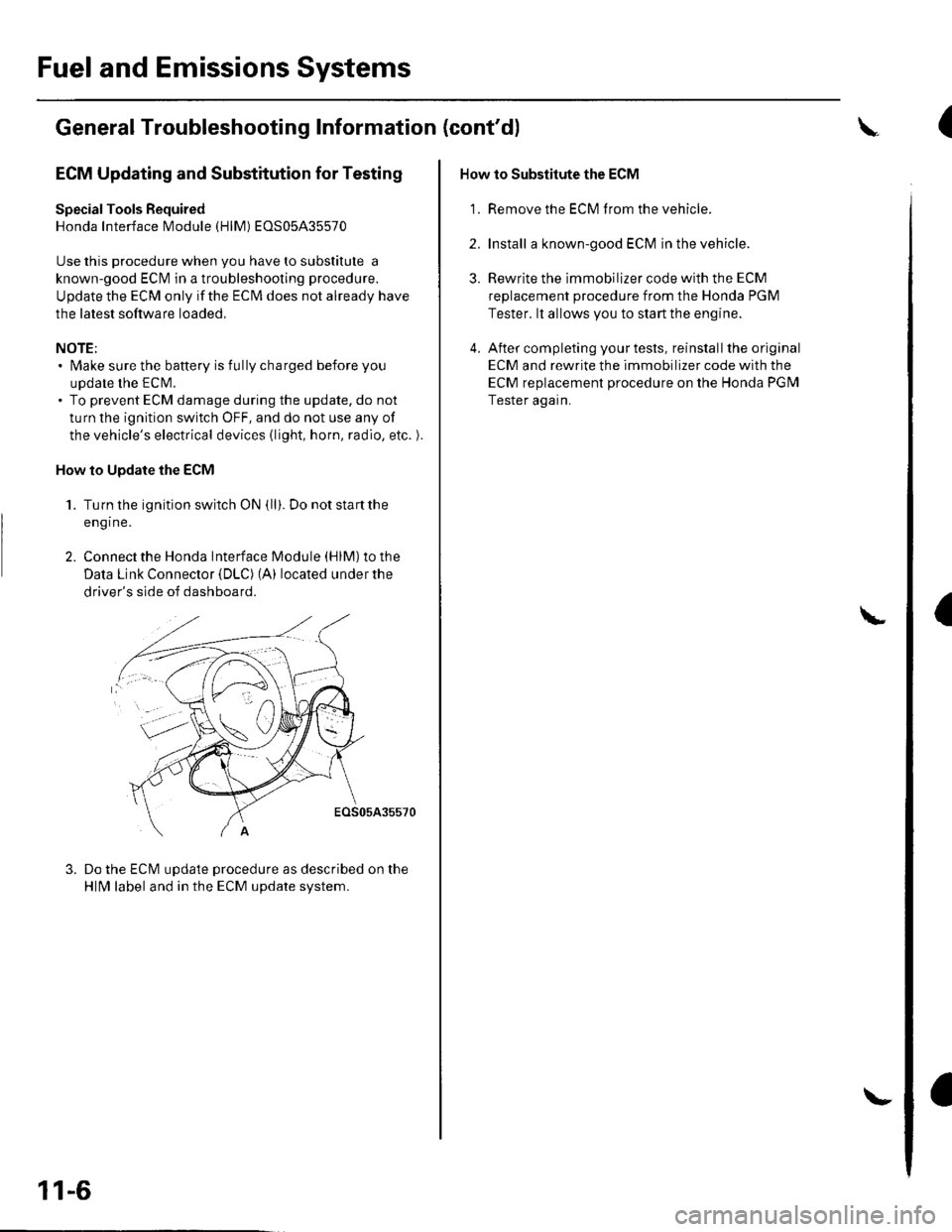
2. Connect the Honda lnterface Module (HlM) to the
Data Link Connector {DLC) (A) located under the
driver's side of dashboard.
EOS05A35570
Do the ECM update procedure as described on the
HlN4 label and in the ECM update system.
11-6
\-
How to Substitute the ECM
'1. Remove the ECM f rom the vehicle.
2. Install a known-good ECM in the vehicle.
3. Rewrite the immobilizer code with the ECM
replacement procedure from the Honda PGM
Tester. lt allows you to start the engine.
4. After completing your tests, reinstall the original
ECM and rewrite the immobilizer code with the
ECM replacement procedure on the Honda PGM
Tester again.
L
(
I
Page 220 of 1139
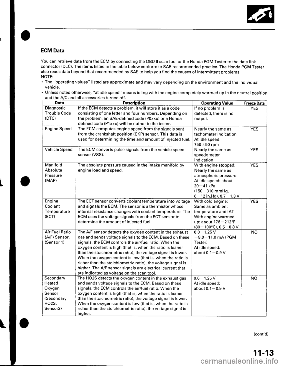
ECM Data
You can retrieve data from the ECI\4 by connecting the OBD ll scan tool or the Honda PGM Tester to the data link
connector (DLC). The items listed in the table below conform to SAE recommended practice. The Honda PGM Tester
also reads data beyond that recommended by SAE to help you find the causes of intermittent problems.
The "operating values" listed are approximate and may vary depending on the environment and the individual
vehicle.
Unless noted otherwise, "at idle speed" means idling with the engine completely warmed up in the neutral position,
and the A,/C and all
Diagnostic
Trouble Code(DTC}
lf the ECM delects a problem, it will store it as a code
consisting of one letter and four numbers. Depending on
the problem, an SAE-defined code (Poxxx) or a Honda,
defined code {P1xxx) will be output to the tester.
The ECI\4 computes engine speed from the signals sent
from the crankshaft position (CKP) sensor. This data is
used for determining the time and amount of injected fuel.
detected, there is no
ourpul.
lf no problem is YES
Nearly the same as
tachometer indication
At idle speed;
The ECM converts pulse signals from the vehicle speed
sensor (VSS).Nearly the same as
speedometer
indication
Manifold
Absolute
Pressure(MAP)
The absolute pressure caused in the intake manifold by
engine load and speed.
With engine stopped: YES
Nearly the same as
almospnenc pressure.
At idle speed: about
20 4'1 kPa(150 310 mmHg,
6- 12 in.Hq).0.7 1.3 V
The ECT sensor converts coolant temperature into voltage
and signals the ECM. The sensor is a thermistor whose
internal resistance changes with coolant tempetature. The
ECM uses the voltage signals from the ECT sensor to
determine the amount of injected fuel.
With cold engine:
Same as ambient
temperature and IAT
With engine warmed
up; about 116 2'12"F
100'c).0.5-0.8 v
Air Fuel Ratio The A,/F sensor detects the oxygen content in the exha ust 0.0 - 1 .25 V(Ay'F) Sensor. gas and sends voltage signals to the Eclvl, Basedonthese 8.0 11.0mA(PGM(Sensor 1) signals, the ECM controls the airlfuel ratio. When the I Tester)
oxygen content is high (that is, when the ratio is leaner At idle speed:
than the stoichiometric ratio), the voltage signal is Iower. about 0.1 0.9 V
When the oxygen content is low (that is, when the ralio is
richer than the stoichiometric ratio). the voltage signal is
higher. The A'lF sensor signals are electrical current that
are indicated as voltaqe on the
The HO2S detects the oxygen content in the exhaust gas
and sends voltage signals to the ECM. Based on these
signals, the ECM controls the airlfuel ratio. When the
oxygen content is high (that is, when the ratio is leaner
than the stoichiometric ratio), the voltage signal is lower.
When the oxygen content is low (that is, when the ratio is
richer than the stoichiometric ratio), the voltage signal is
Secondary
Heated
Oxygen
Sensor(Secondary
H02S,
Sensor2)
0.0 1.25 V NO
At idle speed:
about 0.1 0.9 V
(cont'd)
11-13
Page 226 of 1139
![HONDA CIVIC 2003 7.G Service Manual ECM Inputs and Outputs at Connector A (31P)
NOTE: Standard battery voltage is 12 V.
1AFS]TC2
]GP23IGPl^:^ I -:,6AFS+1
CKPIKS
10
SG2t112ACV15TPST6AFS_18
VSS
19IVAP2Avcc221vccl
22
HTC+
23LG225CMPA
26CM HONDA CIVIC 2003 7.G Service Manual ECM Inputs and Outputs at Connector A (31P)
NOTE: Standard battery voltage is 12 V.
1AFS]TC2
]GP23IGPl^:^ I -:,6AFS+1
CKPIKS
10
SG2t112ACV15TPST6AFS_18
VSS
19IVAP2Avcc221vccl
22
HTC+
23LG225CMPA
26CM](/img/13/5744/w960_5744-225.png)
ECM Inputs and Outputs at Connector A (31P)
NOTE: Standard battery voltage is 12 V.
1AFS]TC2
]GP23IGPl^:^ I -:,6AFS+1
CKPIKS
'10
SG2t112ACV15TPST6AFS_18
VSS
19IVAP2Avcc221vccl
22
HTC+
23LG225CMPA
26CMPB(rDc)
27tGPts,l28rcPts329tGPts230GPLS 1
Wire side ol female terminals
Terminalnumb€rWho colorforminal nameDescriptionSignal
ELKAVHTAFSHTC (AIR FUEL RATIO(4./F)SENSOR HEATERCONTROL}
Drives Ay'F sensor heaterWith ignit'on switch ON {ll): battery voltageWith fully warmed up engine runnang: 0 V
2YEUBLKIGP2 (POWEB SOURCE)Power source for the ECMcircuitWith the ignition switch ON 1ll): battery voltageWith the ionition switch OFF: about 0 V3YEUBLKIGPl {POWER SOURCE)Power source for the ECMWith the ignition swatch ON {ll): battery voltageWith the ionition switch OFF: about 0 V4BLKPG2 (POWER GROUNDGround forthe ECM circuitLess than 1.0 V at all times5BLKPG1 (POWER GROUNDGround forthe ECM circuitLess than 1.0 V at all times6REDAFS + (AIR FUEL RATIO(A,/F}SENSOR, SENSOR 1+ stDE)
Detects Ay'F sensor{sensor 1) signal
18LUCKP (CRANKSHAFTPOSITION SENSOR)Detects CKP sensor signalWith engine running: pulses
9BED/BLU)K SENSOB)Detects knock sensor siqnalWith enqine knocking: pulses10YEL2 {SENSOR;ROUND);ROUND)Sensor qrounrLessthan 1.0V at elltimesG1 {SENSORSensor qroun(Lessthan 1.0V at alltimes12BLIVREDIACV (IDLE AIR CONTROL(IAC)VALVE)Drives IAC valveWith engine runningr duty controlled
RED/BLKTPS (THROTTLE POSITIONSENSOR)Detects TP sensor signalWith throttle fully open: about 4.8 VWith thronle fullv closed: ahout 0-5 VREDI/ELAFS (AIR FUEL RATIO(4,/F)SENSOR, SENSOB 1SIDE)
Detects !y'F sensor(sensor 1)signal
18WHT/GRNVSS (VEHICLE SPEEDSENSOR)Detects VSS signalWath ignition switch ON (lli and front wheelsrotating: cycles from about 0 V to about 5 V or
(cont'd)
11-19
Page 227 of 1139
![HONDA CIVIC 2003 7.G Service Manual Fuel and Emissions Systems
System Descriptions {contd)
ECM Inputs and Outputs at Connector A (31P)
\. il
Wire side of female terminals
\.
1AFS]TC2
GP2
3IGPl4PG25PG.16AFS+1
CKP
IKS
10SG211sG1
12IACV
HONDA CIVIC 2003 7.G Service Manual Fuel and Emissions Systems
System Descriptions {contd)
ECM Inputs and Outputs at Connector A (31P)
\. il
Wire side of female terminals
\.
1AFS]TC2
GP2
3IGPl4PG25PG.16AFS+1
CKP
IKS
10SG211sG1
12IACV](/img/13/5744/w960_5744-226.png)
Fuel and Emissions Systems
System Descriptions {cont'd)
ECM Inputs and Outputs at Connector A (31P)
\. il
Wire side of female terminals
\.
1AFS]TC2
GP2
3IGPl4PG25PG.16AFS+1
CKP
IKS
10SG211sG1
12IACV
'15
TPS16AFS_18
VSS
19IVAP20vcc221vccl
22AFSHTC+
23LG225
Ct\.4PA
26CMPB(rDc)
27IGPLS428IGPLS329IGPLS230IGPLS,I
NOTE: Standard battery voltage is 12 V.
JorminalnumberWirecolor[€rminal namoDescriptionSignal
19GRN/REDMAP (MANIFOLDABSOLUTE PRESSURESENSOR)
Detects MAP sensor signalWith ignition switch ON (ll):about3 VAt idle: about 1.0 V (depending on enginespeed)
20YEUBLUVCC2 (SENSOR VOLTAGE)Provides sensor voltageWith ignition switch ON {ll): about 5 VWith ionition switch OFF: about0V21YEUREDVCC] (SENSOB VOLTAGE)Provides sensor voltageWith ignition switch ON {ll): about 5 VWith ionition switch OFF: about0V22AFSHTC - (AIR FUELRATIO (A"iFiSENSORHEATER CONTROL + SIDE)
Detects a,/F sensor heatervoltageWith ign;tion switch ON lll): banery voltage
23BRN?ryE LLG2 (LOGIC GROUNDround for the ECM circuLessthan 1.0 V at alltimes24BRN?ryE L1(Lround for the ECM circuLess than '1.0 V at alltimes25B LU,^/VHTCMP A (CAMSHAFT
POSITION SENSOR A)Detects CMP sensor AstonalWith engine running: pulses
26GRNCMP B CAMSHAFTPOSITION (CMP)SENSOBB (TDC (TOP DEAD CENTERSENSORi)
Detects CMP sensor 8 (TDc
sensor)With engine running: pulses
27BRNIGPLS4 {No. 4IGNITIONCOIL PULSE)Drives No, 4 ignition coiWith ignition switch ON (ll)r about 0 vWith engine running: pulses28WHT/BLUIGPLS3 {No.3IGNITIONCOIL PULSE)Orives No.3 rgnition coi
29BLU/REDlGPLS2lNo.2 IGNITIONCOIL PTJLSE)Drives No.2 ignition coil
30YEUGRNIGPLSI (No. 1 IGNITIONco
PlltsF)Drives No. I ignition coil
11-20
\.
a
a
Page 229 of 1139
![HONDA CIVIC 2003 7.G Service Manual Fuel and Emissions Systems
System Descriptions (contdl
ECM lnputs and Outputs at Connector E (31P}
L
u
1iMoFPR
2sr-{]zs3LG34SG3
6$1025HTC
1M RLY
8AFSHTCR
I
14FTP15ELD
16EPSLD
18ACC20Z/VBS21VSV
22BKSW HONDA CIVIC 2003 7.G Service Manual Fuel and Emissions Systems
System Descriptions (contdl
ECM lnputs and Outputs at Connector E (31P}
L
u
1iMoFPR
2sr-{]zs3LG34SG3
6$1025HTC
1M RLY
8AFSHTCR
I
14FTP15ELD
16EPSLD
18ACC20Z/VBS21VSV
22BKSW](/img/13/5744/w960_5744-228.png)
Fuel and Emissions Systems
System Descriptions (cont'dl
ECM lnputs and Outputs at Connector E (31P}
L
u
1iMoFPR
2sr-{]zs3LG34SG3
6$1025HTC
1M RLY
8AFSHTCR
I
14FTP15ELD
16EPSLD
18ACC20Z/VBS21VSV
22BKSW23K-LINE24SEFMJ26NEP
21rMoCD
29scs30WEN31MIL
Wire side of female terminals
NOTE: Standard battery voltage is '12 V.
TerminalnumberWire colorferminal nameDescription Signal
GRNI/ELIMO FPR (IMMOBILIZERFLJEL PUMP RELAYIDrives PGM Fl main relay 20Vfor2 seconds after turning ignition switch ON{ll). then batterv voltaoe2WHT/REDSHO2S (SECONDARYHEATED OXYGEN SENSOR(SECONDARY HO2S),SENSOR 2r
Detects secondary HO2S{sensor 2) signalWith throttle Jully opened from idle with fullywarmed up engine: above 0.6VWith throttle quickly closed: below 0.4 V
3BRN/YELLG3 (LOGIC GROUND)cround forthe ECM/PCMcontrolcircuitLess than 1.0 V at all times
4PNKSG3 {SENSOR GBOUND)Sensor oroundLess than 1.0 V at all times5YEUELUVCC3 {SENSOR VOLTAGE)Provides sensor voltageWith ignition switch ON (ll): about 5 VWith ionition switch OFF: about 0 V6BLKATr'HTSO25HTC (SECONDARYHEATED OXYGEN SENSOR(SECONDARY H02S)HEATER CONTROL)
Drives secondary HO2SheaterWith ignition switch ON (ll): baftery voltageWilh fullv warmed up engine running: dul,controlled
1REDA/ELMRLY (PGM.FI MAINRELAY}Drives PGM-Flmain relay 1Power source forthe DTCWith ignition switch ON (ll): about 0 VWith ignition switch OFF: battery voltage
IORNAFSHTCR {AIR FUEL BATIO(Iy'F)SENSOR HEATERCONTROL RELAY)
Drives air fuel ratio sensorheater relayWith ignition swirch ON {ll): 0 V
IYEUBLKIGl (IGNITION SIGNAL)Detecrs ignition signalWith ignition switch ON (ll): battery voltageWith iqnition switch OFF: about 0 V't4LT GRNFIP lFUEL TANKPRESSURE (FTP) SENSOR)Detects FTP sensor signalWith ignition switch ON (ll) and fuel fill cap open:about 2.5 VGRN/REDELD (ELECTRICAL LOADDETECTOF)Detects ELD signalWith ignition swjtch ON itt):aOoutO.t V l-gV(deDendino on electrical load)LT GRN/8LKEPSLD (ELECIRICALPOWEB STEEBING LOADDETECT)
Detects Power steering loadsrgnalAt idle with steering wheel in straight aheadposition: about 0 VAt idle with steering wheelatfull lock: momentary
'18REDACC (Ay'C CLUTCH RELAY)Drives P,/C clutch relayWith compressor ON: about 0 VWith comoressor OFF: batterv voltaoe
11-22
\-
Page 230 of 1139
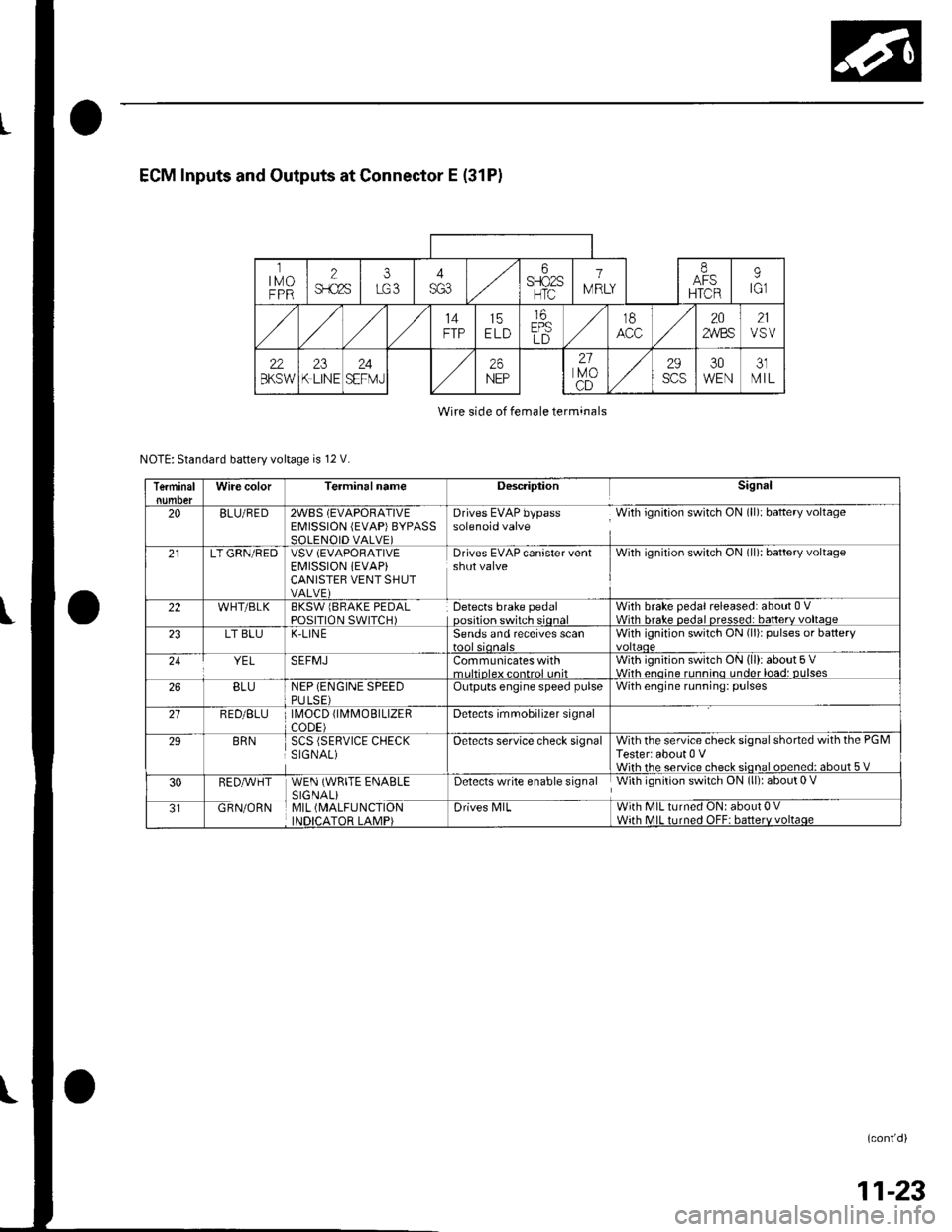
ECM Inputs and Outputs at Connector E (31P)
ltMoFPR
2$.c2s
i6SFIO2SHTC
1
IV RLY
IAFSHTCR
9tGl
14FTP15ELD
16EPSLD
t8202,4/BS21VSV
22BKSW23K LINE24SEFMJ26NEP
21lvoCD
29scs30WEN31MIL
Wire side of female terminals
NOTE: Standard battery voltage is 12 V.
TerminalWire colorTerminalnameDescriptionSignal
20BLU/RED2WBS (EVAPORATIVEEMISSION (EVAP)BYPASSSOLENOID VALVE)
Drives EVAP bypass With ignition switch ON (ll): baftery voltagesolenoid valve
21LT GRN/REDVSV (EVAPORATIVE
EI\4ISSION iEVAP)CANISTEB VENT SHUTVALVE)
Drives EVAP canister ventshut valveWith ignilion switch ON (ll): battery voltage
22WHT/BLKBKSW lBRAKE PEDALPOSITION SWITCH)Detects brake pedaloosition switch sionalWith brake pedal released: about 0 VWith hrake nedal nresse.l: batterv voltaoe23LT BLUK-LIN ESends and receives scanWith ignition switch ON (li)r pulses or battery
YELSEFMJCommunicates withmrltinleY eontrol unitWith ignition switch ON (ll): about 5 VWith enoine runnino under load: DUlses26BLUNEP (ENGINE SPEEDPULSE)Outputs engine speed pulseWith engine running: pulses
21RED/BLU \40CD fl\4MOBTLTZERCODE)Detects imrnobilizer signal
29BRNSCS (SERVICE CHECKSIGNAL)Oetects service check signalWith the service check signal shorted with the PGMTester: about 0 VWiih rhe service check sional ooened: about 5 V
30RED,A/VHTWEN (WRITE ENABLESIGNALiDetects write enable signal With ignition switch ON (ll): about 0 V
GRN/ORNMIL (MALFUNCTION
INDICATOR LAMP)Drives N4lLWith MIL turned ON: about 0 VWith MIL turned OFF: batterv voltaqe
(cont'd)
11-23
Page 247 of 1139
![HONDA CIVIC 2003 7.G Service Manual Fuel and Emissions Systems
System Descriptions (contdl
ECM Circuit Diagram {contd)
\
-{ffi]---1t-|
IATSENSOR
-{El------l
ECTSENSOS
T_""",,..
I-BFN/YEL
ft^--l
,","., J t-|:I REVERSEI LocKI soleloto+ HONDA CIVIC 2003 7.G Service Manual Fuel and Emissions Systems
System Descriptions (contdl
ECM Circuit Diagram {contd)
\
-{ffi]---1t-|
IATSENSOR
-{El------l
ECTSENSOS
T_""",,..
I-BFN/YEL
ft^--l
,","., J t-|:I REVERSEI LocKI soleloto+](/img/13/5744/w960_5744-246.png)
Fuel and Emissions Systems
System Descriptions (cont'dl
ECM Circuit Diagram {cont'd)
\
-{ffi]---1t-|
IATSENSOR
-{El------l
ECTSENSOS
T_""",,..
I-BFN/YEL
ft^--l
,","., J t-|':I REVERSEI LocKI soleloto+ vaLvE
t!j]]
CMPSENSOAA
L-IJUNCTIONI CONNECTOR
-
11-40
Page 248 of 1139
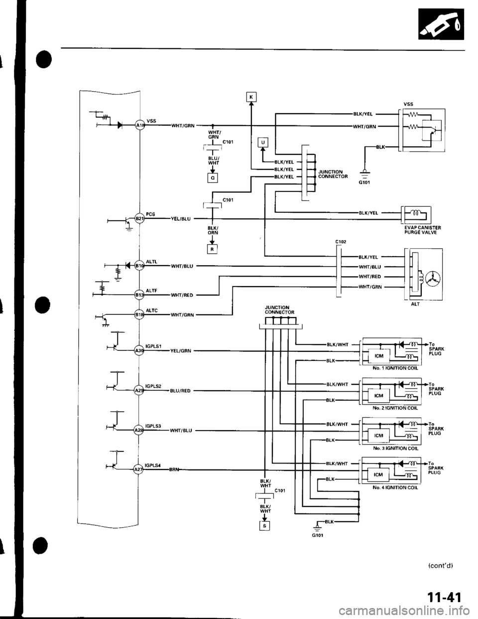
G8Nt,'--r-
BLU/
J.-L9l
H-l .lurcrroru
F
coNNEcroR
_1ffi1
| | -'- |----1 Fahdl
I lrl||T-'8r-K-L- l
EVAPCANISTEB
ALK/YEL
WHT/ALU
WHT/NED
WHI/GRN
JUNCTIONCONNECTOR
rrrn
tcM
No.2IGNITION COlt
No.3IGNITION COIL
PLUG
PLUG
(cont'd)
11-41
Page 252 of 1139
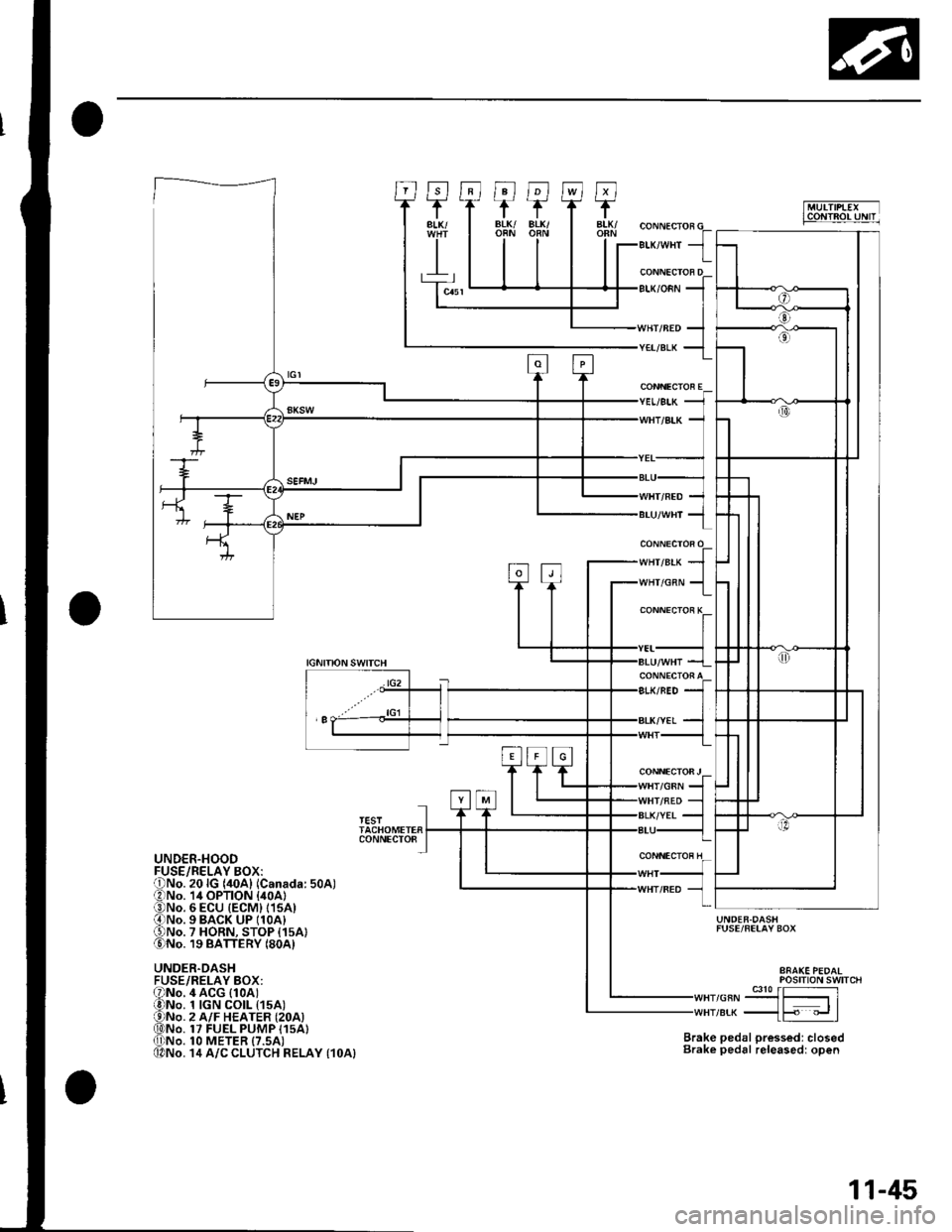
""rr"a* JIr''lHr/cnN 1
CONNECTOR E
CONNECTOi K
CONNECTOFJ/GRN
IGNITIONSWITCH
lG2
'I
TESTTACHOMETERCONNECTO8
UNDER.HOOD
UNDER.DASHFUSE/RELAY BOX:
UNDER.DASHFUSE/FELAY BOX
Brake pedal pressed: closedBrake pedal releasedr open
POStTtON SWTTCH
,or"-9J3{51re* _{F "_.rl
4 ACG (1oAt1 tGN CO|L t15A)2 A/F HEATER {2OA)17 FUEL PUMP I15A}1O METER {7.5AI14 A/C CLUTCH RELAY {1OA}
11-45