Index HONDA CIVIC 2003 7.G Repair Manual
[x] Cancel search | Manufacturer: HONDA, Model Year: 2003, Model line: CIVIC, Model: HONDA CIVIC 2003 7.GPages: 1139, PDF Size: 28.19 MB
Page 624 of 1139
ABS Gomponents
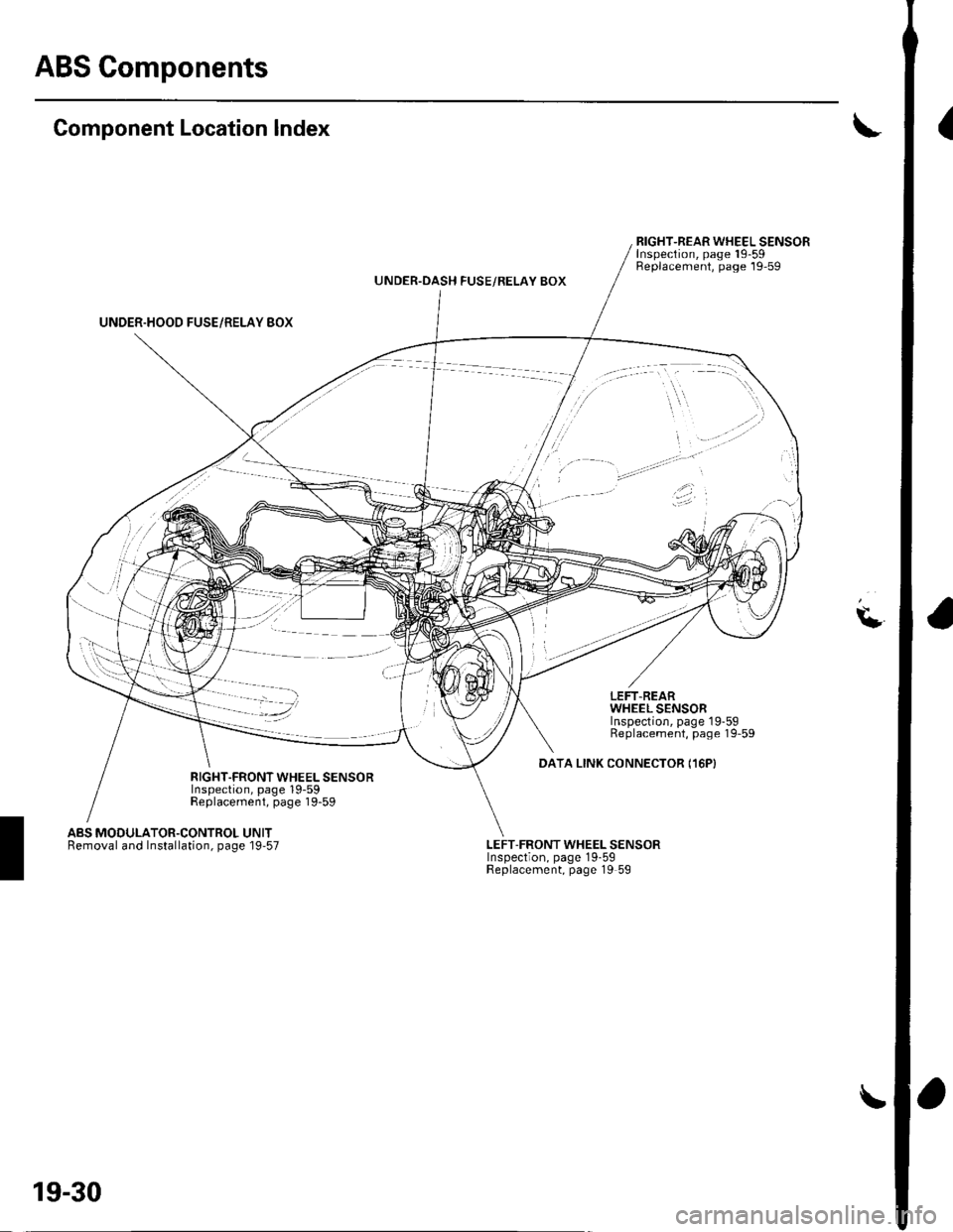
(Component Location Index
UNDER.HOOD FUSE/RELAY BOX
RIGHT-REAR WHEEL SENSORInspection, page 19-59Replacement, page 19-59UNDER.OASH FUSE/RELAY BOX
\L
LEFT.REARWHEEL SENSORInspection, page 19-59Replacement, page 19-59
DATA LINK CONNECTOR I16PIRIGHT.FRONT WHEEL SENSORInspection, page 19-59Replacement, page 19-59
ABS MODULATOR.CONTROL UNITRemoval and Installation, page 19'57LEFT-FRONT WHEEL SENSORInspection, page 19-59Replacement, page 19 59
19-30
Page 626 of 1139
ABS Components
General Troubleshooting Information (cont'd)
How to Troubleshoot ABS DTCs
The troubleshooting flowchart procedures assume that
the cause of the oroblem is still Dresent and the ABS
indicator is still on. Following the flowchart when the
ABS indicator does not come on can result in incorrect
diagnosis.
The connector illustrations show the female terminal
connectors with a single outline and the male terminal
connectors with a double outline.
1. Ouestion the customer about the conditions when
the problem occured, and try to reproduce the
same conditions for troubleshooting. Find out
when the ABS indicator came on, such as during
ABS control, after ABS control, when the vehicle
was at a certain speed, etc.
2. When the ABS indicator does not come on during
the test-drive, but troubleshooting is done based on
the DTC, check for loose connectors. poor terminal
contact, etc., before you start troubleshooting.
3. After troubleshooting, clear the DTC,disconnect the
Honda PGM Tester. and test-drive the vehicle.
Make sure the ABS indicator does not come on.
How to Retrieve ABS DTCs
Honda PGM Tester Method:
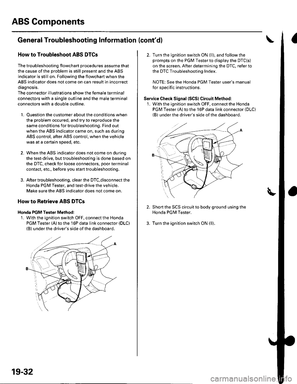
1, Wjth the ignition switch OFF, connect the Honda
PGM Tester (A) to the 16P data link connector (DLC)
(B) under the driver's side of the dashboard.
19-32
2. Turn the ignition switch ON (ll), and follow the
prompts on the PGM Tester to display the DTC{S)
on the screen. After determining the DTC, refer to
the DTC Troubleshooting Index.
NOTE: See the Honda PGM Tester user's manual
for specific instructions.
Service Check Signal (SCS) Circuit Method:
1. With the ignition switch OFF, connect the Honda
PGM Tester (A) to the 16P data link connector (DLC)
(BI under the driver's side of the dashboard.
2. Short the SCS circuit to body ground using the
Honda PGM Tester.
3. Turn the ignition switch ON (ll).
Page 627 of 1139
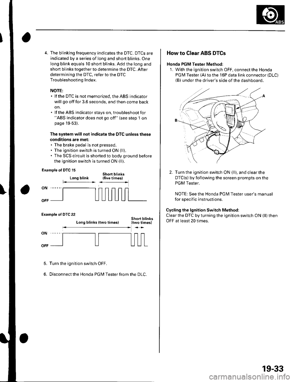
4. The blinking frequency indicates the DTC. DTCS are
indicated by a series of long and short blinks. One
long blink equals 10 shon blinks. Add the long and
short blinks together to determine the DTC. After
determining the DTC, refer to the DTC
Troubleshooting Index.
NOTE:. lf the DTC is not memorized, the ABS indicator
will go off for 3.6 seconds, and then come back
on.. lf the ABS indicatorstays on, troubleshootfor"ABS indicator does not go off" (see step 1 onpage 19-53).
Th€ system will not indicate the DTC unless these
conditions are met:. The brake pedal is not pressed.. The ignition switch is turned ON {ll).. The SCS circuit is shorted to body ground before
the ignition switch is turned ON (ll).
Example ot DTC 15
Long blinkShort blinks{five timesl
Examole of DTC 22
Long blinks (two times)
Turn the ignition swltch OFF,
Disconnect the Honda PG M Tester from the DLC.
5.
How to Clear ABS DTCs
Honda PGM Tester Method:
1. With the ignition switch OFF, connect the Honda
PGM Tester (A)to the l6Pdata link connector (DLC)
{B} under the driver's side of the dashboard.
Turn the ignition switch ON (ll), and clearthe
DTC(s) by following the screen prompts on the
PGM Tester.
NOTE: See the Honda PG l\4 Tester user's manual
for sDeclf ic instructions.
Cycling the lgnition Switch Method:
Clear the DTC by turning the ignition switch ON (ll) then
OFF at least 20 times.
19-33
Page 628 of 1139
ABS Gomponents
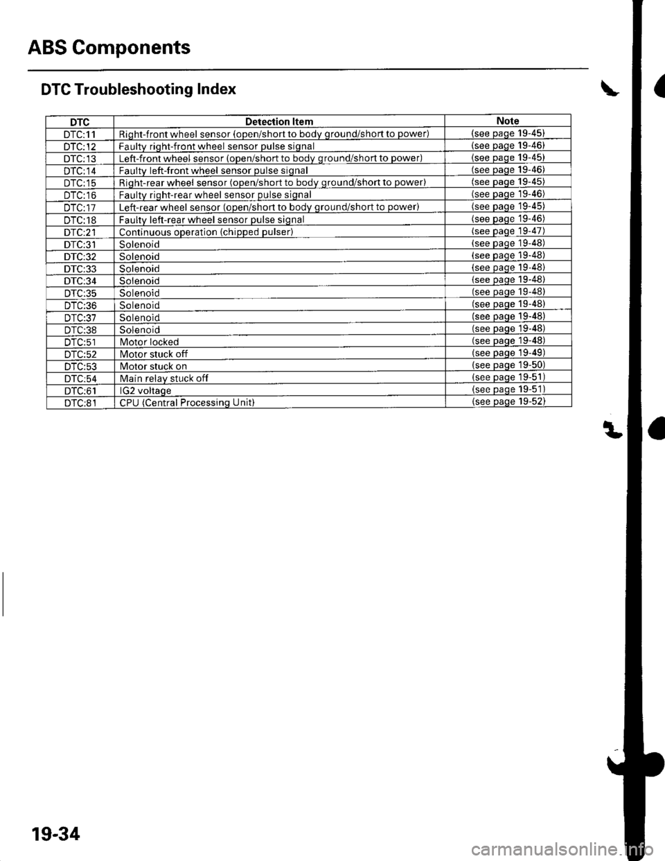
DTC Troubleshooting Index
DTCDetection ltemNote
DTC:11Rioht-front wheel sensor {ooen/short to bodv qround/short to power)(see oaoe 19-45)
DTC:12Faultv riqht-front wheel sensor oulse siqnal{see oaoe 19-46)
DTC:13Left-front wheel sensor {oDen/short to bodv qround/short to power)(see oaqe 19-45)
DTC:14Faultv left-front wheel sensor Dulse srqnal(see paqe 19-46)
DTC;15Riqht-rear wheel sensor (oDen/short to bodv qround/short to power)(see Daqe 19-45)
DTC:16Faultv riqht-rear wheel sensor oulse siqnal(see paqe 19-46)
DTC:17Left-rear wheel sensor (open/short to bodv qround/short to power)(see Daoe '19-45)
DTC:18Faultv left-rear wheel sensor Dulse siqnal(see Daqe '19-46)
Drc:2lContinuous oDeration (chioDed Dulser)(see paqe 19-47)
DTC:3'lSolenoid(see Daoe 19-48)
DTC:32Solenoid{see Daqe 19-48)
DTC:33Solenoid{see Daoe 19'48)
DTC:34Solenoidlsee oaqe 19-48)
DTC:35Solenoid(see paqe 19-48)
DTC;36So le no id(see Daqe 19-48)
DTC:37So le noid(see Daqe 19-48)
DTC:38Sole no id(see Daoe 19-48)
DTC:51lvlotor Iocked(see Daqe 19-48)
DTC:52lvlotor stuck off(see Daoe 19-49)
DTC:53lMotor stuck on(see Daoe 19-50)
DTC:54Main relav stuck off(see paqe 19-51
DTC:61lG2 voltaqe{see oaqe 19-5'l
DTC:81cPU (Central Processinq Unit){see paqe 19-52)
19-34
Page 629 of 1139
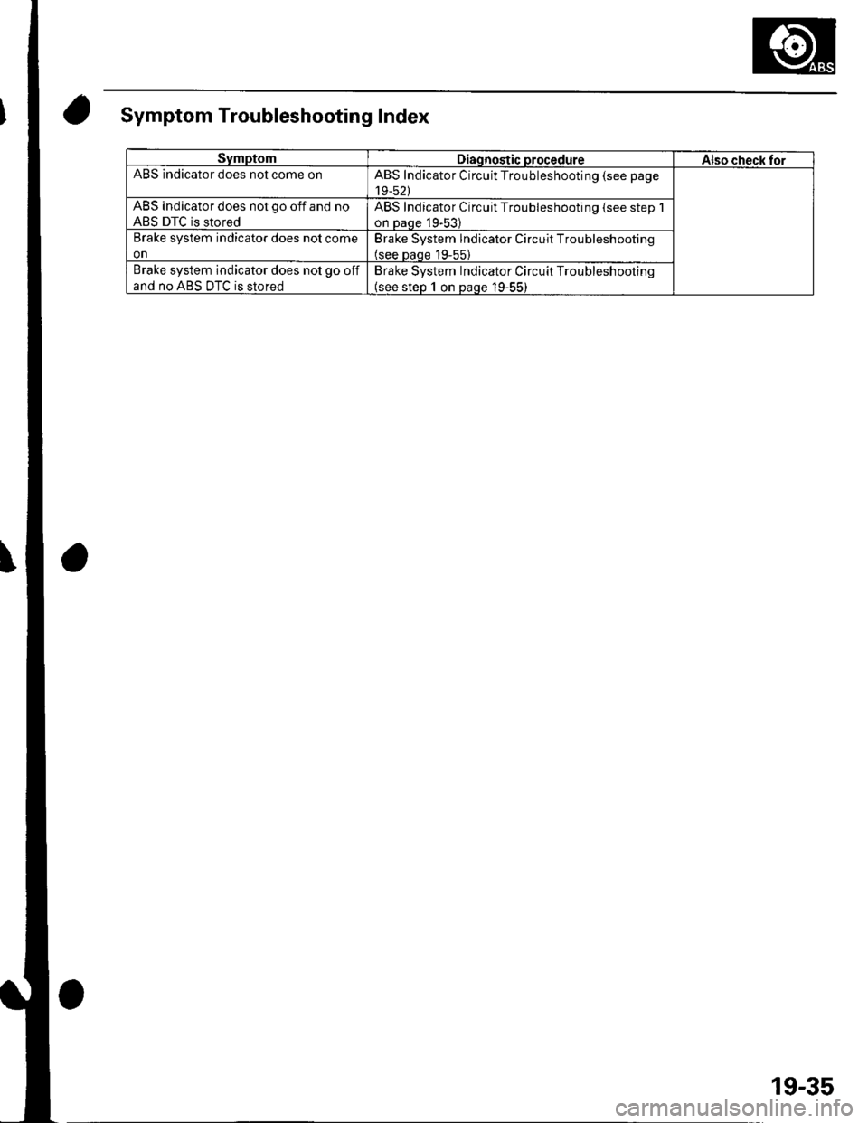
Symptom Troubleshootin g Index
SymptomDiagnostic procedureAlso check forABS indicator does nol come onABS Indicator Circuit Troubleshooting (see page
19-52)
ABS indicator does not go off and no
ABS DTC is stored
ABS Indicator Circuit Troubleshooting {see step 1
on Daqe 19-53)
Brake system indicator does nol come
on
Brake System lndicator Circuit Troubleshooting(see paqe 19-55)
Brake system indicator does not go off
and no ABS DTC is stored
Brake System Indicator Circuit Troubleshooting(see steo 1 on Daqe 19-55)
19-35
Page 654 of 1139
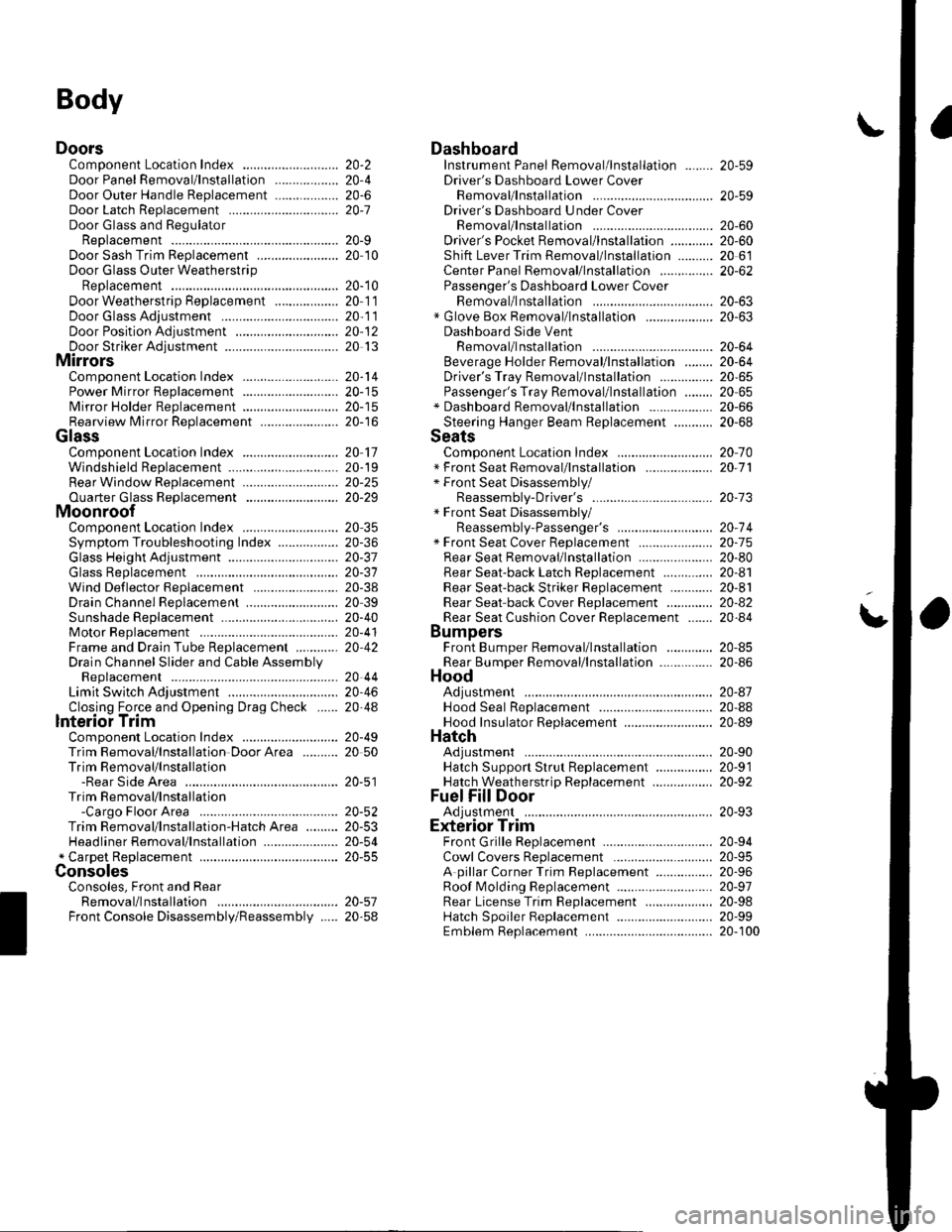
Body
DoorsComponent Location Index ...........Door Panel Removal/lnstallation .....,..........Door Outer Handle ReplacementDoor Latch ReplacementDoor Glass and RegulatorReplacementDoor Sash Trim Replacement .......................
Door Glass Outer WeatherstripReplacement
Door Weatherstrip Beplacement
Door Glass Adjustment .................................Door Position Adjustment .............................Door Striker Adiustment ................................MirrorsComponent Location Index ...........................Power Mirror Replacement ...........................Mirror Holder Replacement ...........................Rearview Mirror Rep1acement ......................
GlassComponent Location Index ...........................Windshield Replacement
Bear Window Rep1acement ...........................
Ouarter Glass Replacement ..........................MoonroofComponent Location Index ...........................Symptom Troubleshooting Index
Glass Height Adjustment ...............................
Glass ReplacementWind Def lector 8ep1acement ........................Drain Channel Rep1acement ..........................Sunshade Replacement .................................Motor ReplacementFrame and Drain Tube Replacement ............Drain Channel Slider and Cable AssemblyReplacementLimit Switch Adjustment ...............................Closino Force and ODenina Draq Check ......lnterioi TrimComponent Location Index ...........................Trim Removal/lnstallation DoorArea ..........Trim Removal/lnstallation-Rear Side AreaTrim Removal/lnstallation-Cargo Floor AreaTrim Removal/lnstallation-Hatch Area .........Headliner Removal/lnstallation* Carpet Rep1acement .......................................ConsolesConsoles, Front and RearRemova l/lnsta llationFront Console Disassembly/Reassembly .....
20-220,420-620-7
20-920 t0
20- 10
20-1120-1120-1220 13
20-1420-1520-1520-16
20 1120-1920-2520-29
20,3520-3620-3720-3120-3820 3920-4020-4120,42
20 4420-4620,44
20-4920 50
20-51
DashboardInstrument Panel Removal/lnstallation ........Driver's Dashboard Lower CoverRemovat InstallationDriver's Dashboard Under CoverRemova t Insta llation
Oriver's Pocket Removal/lnstallation ............Shift Lever Trim Removal/lnstallation ..........Center Panel Removal/lnstallation ...............Passenger's Dashboard Lower CoverRemova l/lnsta llat ionx Glove Box Removal/lnstallationDashboard Side VentRemoval/lnstallation .................................. 20-64Beverage Holder Removal/lnstallation ........ 20-64Driver'sTray Removal/lnstallation ............... 20-65Passenger's Tray Removal/lnstallation ........ 20 65* Dashboard Removal/lnstallation .................. 20-66Steerinq Hanqer Beam Reolacement ........... 20-68Seats "
Component Location Index ........................... 20-10* Front Seat Removal/lnstallation ................... 20-11* Front Seat Disassembly/Reassembly-Driver's .................................. 20-73* Front Seat Disassembly/Reassembly-Passenger's ........................... 20-74* Front Seat Cover Replacement ..................... 2O-75Rear Seat Removal/1nsta11ation ..................... 20-80Rear Seat-back Latch Replacement .............. 20-81Rear Seat-backStriker Replacement ............ 20-81
20-59
20-59
Rear Seat-back Cover Replacement ............. 20-82Rear Seat Cushion Cover Replacement ....... 20.84BumpersFront Bumper Removal/lnstallation .............Rear Bumoer Removal/lnstallation ...............HoodAdjustmentHood Seal ReplacementHood Insulator Rep1acement .........................Hatch
20-6020,6020 6120-62
20-63
20-63
20,8520-86
20-4720,8820,89
20-5220-5320-5420-55
20-5720-58
Adjustment ................... 20-90Hatch Suppon Strut Replacement ................ 20-91Hatch WeatherstriD Reo1acement ................. 20-92
Fuel Fill DoorAdiustment ................... 20-93Exterior TrimFront Grille Replacement ..............Cowl Covers Replac"rn""t .. . .....................A pillar Corner Trim Replacement ................Roof lMolding Replacement ...........................Rear License Trim ReplacementHatch Spoiler 8ep1acement ...........................Emblem Rep1acement .........................
20-9420-9520-9620-9720,9820-9920-100
Page 655 of 1139
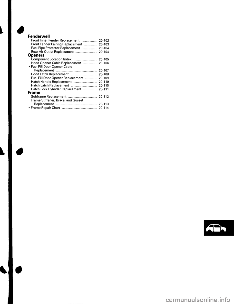
FenderwellFront Inner Fender ReplacementFront Fender Fairing Replacement ...............Fuel Pipe Protector ReplacementRear Air Outlet Rep1acement .........................OpenersComponent Location Index ...........................Hood Opener Cable Replacement ................* Fuel Fill Door Opener CableReplacement
Hood Latch Rep1acement ..............................Fuel Fill Door Opener Replacement ..............Hatch Handle Replacement ...........................Hatch Latch Replacement ..............................Hatch Lock Cylinder Replacement ................FrameSubf rame Replacement ................................. 20-112Frame Stiffener, Brace, and GussetReplacement ............. 20-113r Fremp RFnrir Chrrr ................ 20-114
20-10220-10320-10420-'to4
20-10520-106
20 107
20-10820-10920-1 1020-11020-111
Page 656 of 1139
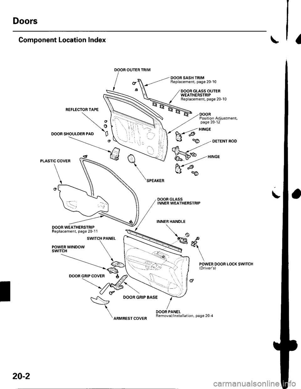
Doors
Component Location Index
POWER WINDOWswtTcH
a
DOOR SASH TRIMReplacement, page 20-10
DOOR GLASS OUTERWEATHERSTRIPReplacement, page 20-10
DOORPosition Adiustment,page 20-12
t
\POWER DOOR LOCK SWITCH(Driver's)
DOOR OUTER TRIM
K-pIJ A'A
dq
W2"'
Ya\J aita.
DOOR WEATHERSTRIPReplacement, page 20-'l'l
20-2
Page 668 of 1139
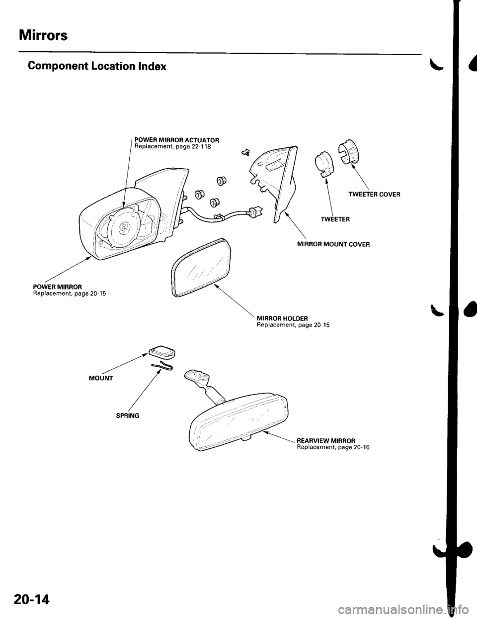
Mirrors
Component Location Index
POWER MIRRORReplacement, page 20-15
.a b\.\| \-r<,,/
\.J \\.4 \
1\
TWEETER
TWEETER
MIRROR MOUNT COVER
MIRROR HOLDERReplacement, page 20 '15
__.Q
-'-'MOUNT
/
/
REARVIEW MIRRORReplacement, page 20 16
POWER MIRROR ACTUATORReplacement, page 22-1'18
20-14
Page 671 of 1139
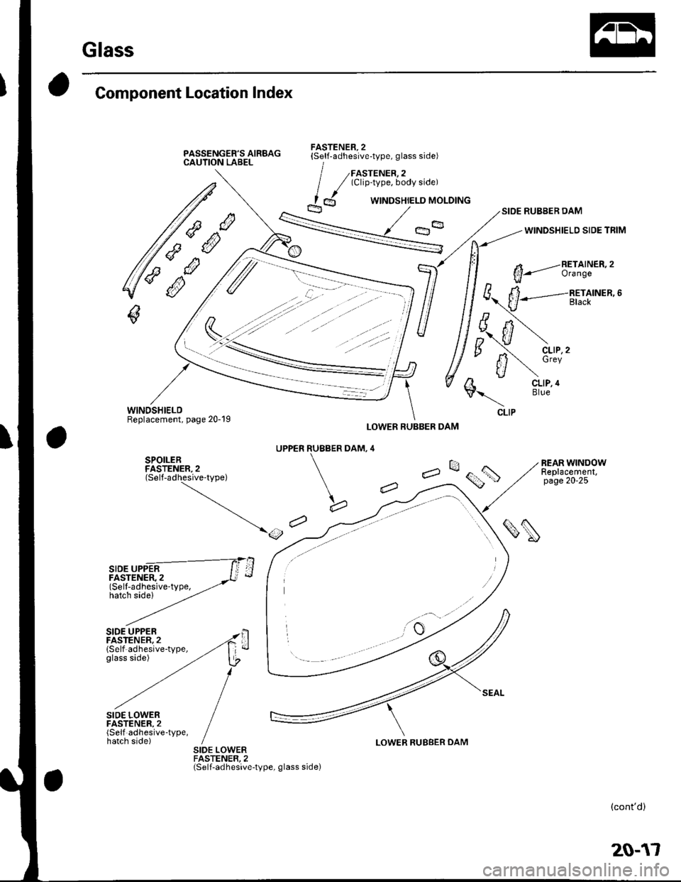
Glass
Component Location Index
PASSENGER'S AIRSAGCAUTION LABEL
FASTENER,2{Self-adhesive-type, glass side)
SIDE RUBBER DAM
WINDSHIELD SIDE TRIM
m-_-==}lny' ',
S{|---..------'RErA'NER,6
f..N; J \
e
N8*?'�CLIP,4Blue
CLIPWINDSHIELDBeplacement, page 20-19
SPOILERFASTENER, 2(Selt-adhesive-type)
LOWER RUBBER DAM
UPPER RUBBER DAM, 4
(cont'd)
4
'9>
LOWER RUBBER DAM
20-17