HONDA CIVIC 2003 7.G Repair Manual
Manufacturer: HONDA, Model Year: 2003, Model line: CIVIC, Model: HONDA CIVIC 2003 7.GPages: 1139, PDF Size: 28.19 MB
Page 61 of 1139
Charging System
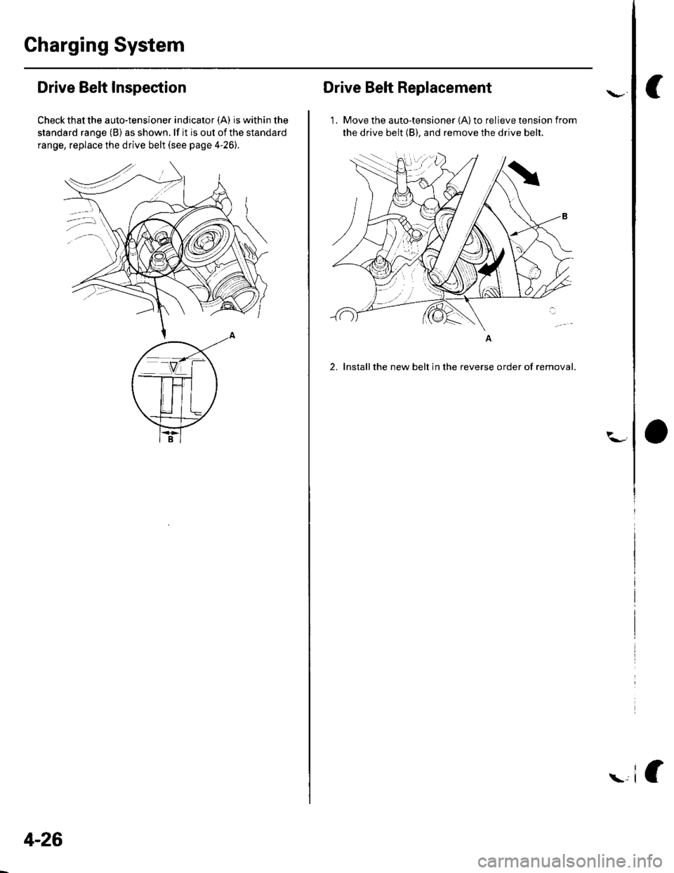
Drive Belt Inspection
Check that the auto-tensioner indicator (A) is within the
standard range (B) as shown. lf it is out of the standard
range, replace the drive belt (see page 4-26).
4-26
Drive Belt Replacement
1, Move the auto-tensioner (A) to relieve tension from
the drive belt (B). and remove the drive belt.
2. Installthe new belt in the reverse order of removal.
Page 62 of 1139
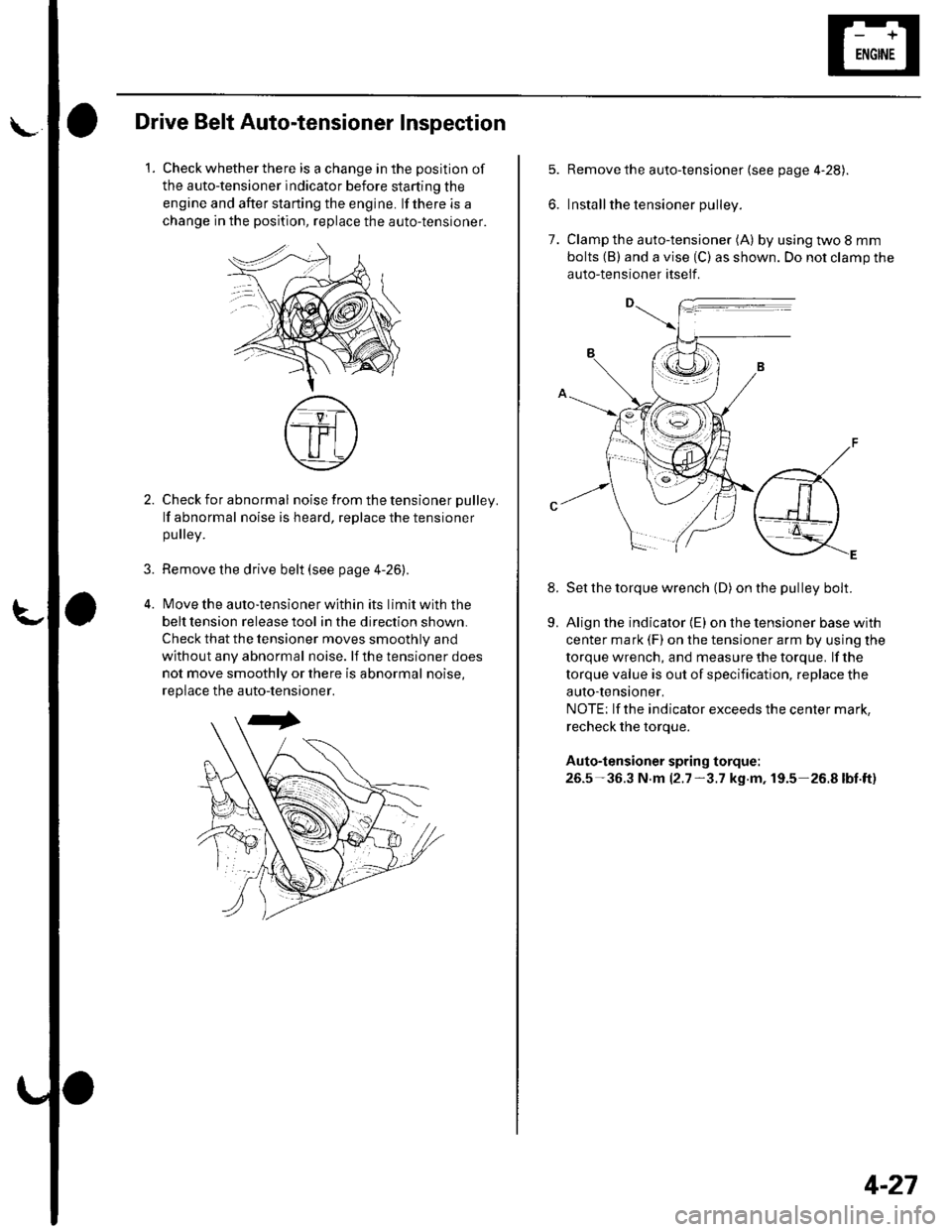
\Drive Belt Auto-tensioner Inspection
1.Check whether there is a change in the position of
the auto-tensioner indicator before starting the
engine and after starting the engine. lf there is a
change in the position, replace the auto-tensioner.
3.
Check for abnormal noise from the tensioner pulley.
lf abnormal noise is heard, replace the tensioner
pulley.
Remove the drive belt (see page 4-26).
lMove the auto-tensioner within its limit with the
belt tension release tool in the direction shown.
Check that the tensioner moves smoothly and
without any abnormal noise. lf the tensioner does
not move smoothly or there is abnormal noise,
replace the auto-tensioner.
7.
8.
Remove the auto-tensioner (see page 4-28).
Install the tensioner pulley.
Clamp the auto-tensioner (A) by using two 8 mm
bolts (B) and a vise (C) as shown. Do not clamp the
auto-tensioner itself .
Set the torque wrench (D) on the pulley bolt.
Align the indicator {E) on the tensioner base with
center mark (F) on the tensioner arm by using the
torque wrench, and measure the torque. lf the
torque value is out of specification, replace the
auto-tensioner,
NOTE; lf the indicator exceeds the center mark,
recheck the torque.
Auto-tensioner spring torque:
26.5-36.3 N.m 12.7-3.7 kg.m, 19.5-26.8lbt.ft)
9.
4-27
Page 63 of 1139
Charging System
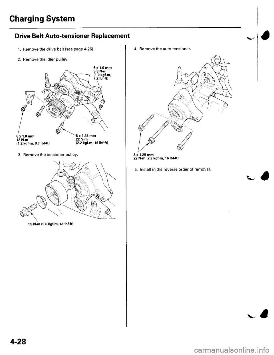
Drive Belt Auto-tensioner Replacement
1. Remove the drive belt (see page 4'26).
2. Remove the idler pulley.
6xl.0mm9.8 N.m(1,0 kgl.m,7.2 tbf.ft)
d
I6x1,0mm12 N.m('1.2 kgt.m.8.7 lbt.ft)
3. Remove the tensioner pulley.
x 1.25 mm22 N.m{2.2 kgt m, 16 lbf ft}
4-28
4. Remove the auto-tensioner,
8 x 1.25 mm22 N.m (2.2 kgf.m, 16lbt.ft)
5. lnstall in the reverse order of removal.
\-a
Page 64 of 1139
l\-Alternator Replacement
1. Make sure you have the anti-theft code for the radio,
then write down the frequencies for the radio'spreset buttons,
2. Disconnect the negative cable from the battery first,
then disconnect the positive cable.
3. Remove the front bumper (see page 20-85).
4. Remove the right side headlight (see page 22-79).
5. Remove the reserve tank from the bracket.
6. Remove the drive belt (see page 4-26).
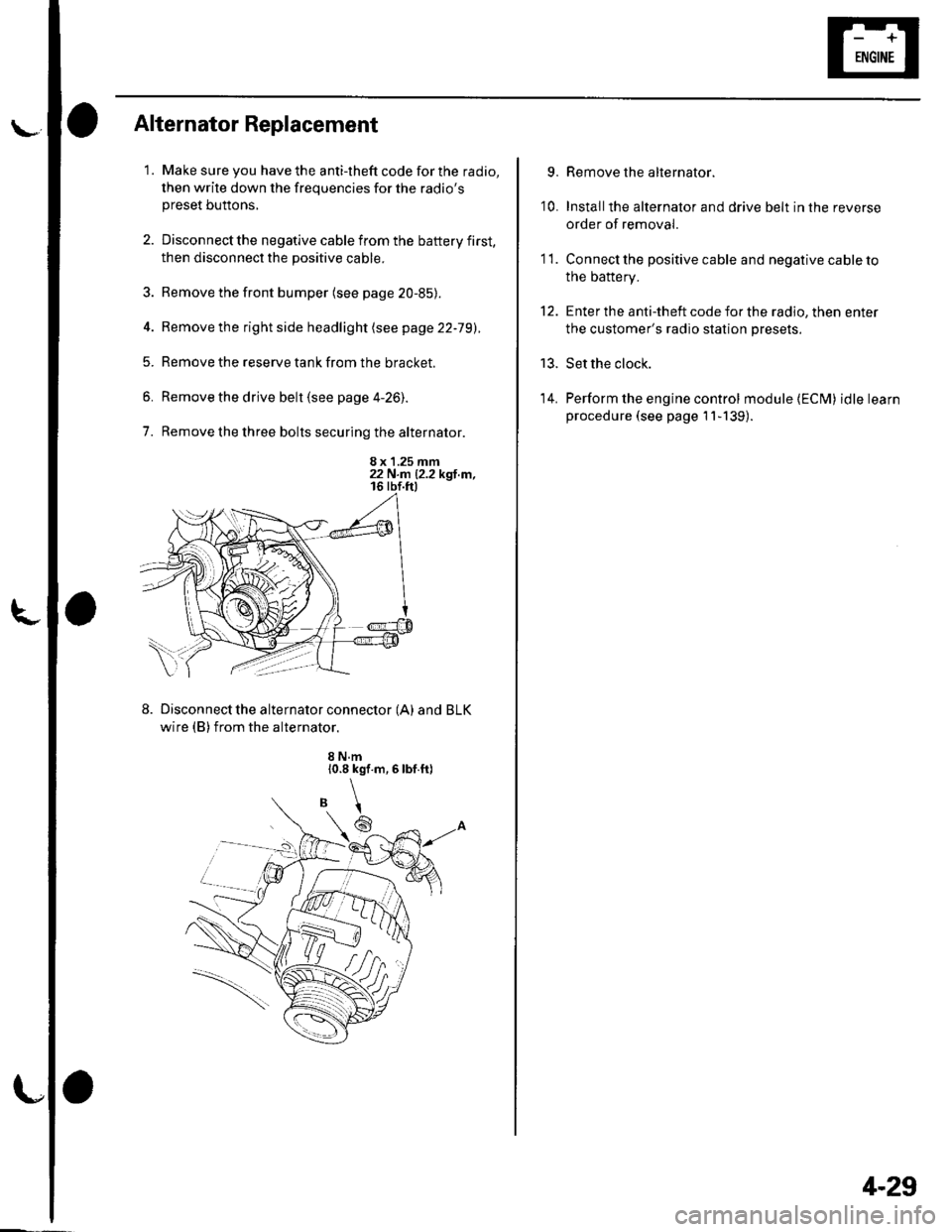
7. Remove the three bolts securing the alternator.
8 x 1.25 mm22 N.n 12.2 kgl.m,
Disconnect the alternator connector (A) and BLK
wire (B) from the alternator.
8 N.m10.8 kgf.m,6lbf.ft)
\
6
'I 1.
9.
10.
13.
14.
Remove the alternator.
Installthe alternator and drive belt in the reverse
order of removal.
Connect the positive cable and negative cable to
the battery.
Enter the anti-theft code for the radio, then enter
the customer's radio station presets.
Set the clock.
Perform the engine control module {ECM) idle learn
procedure (see page 11-139).
tt.
4-29
Page 65 of 1139
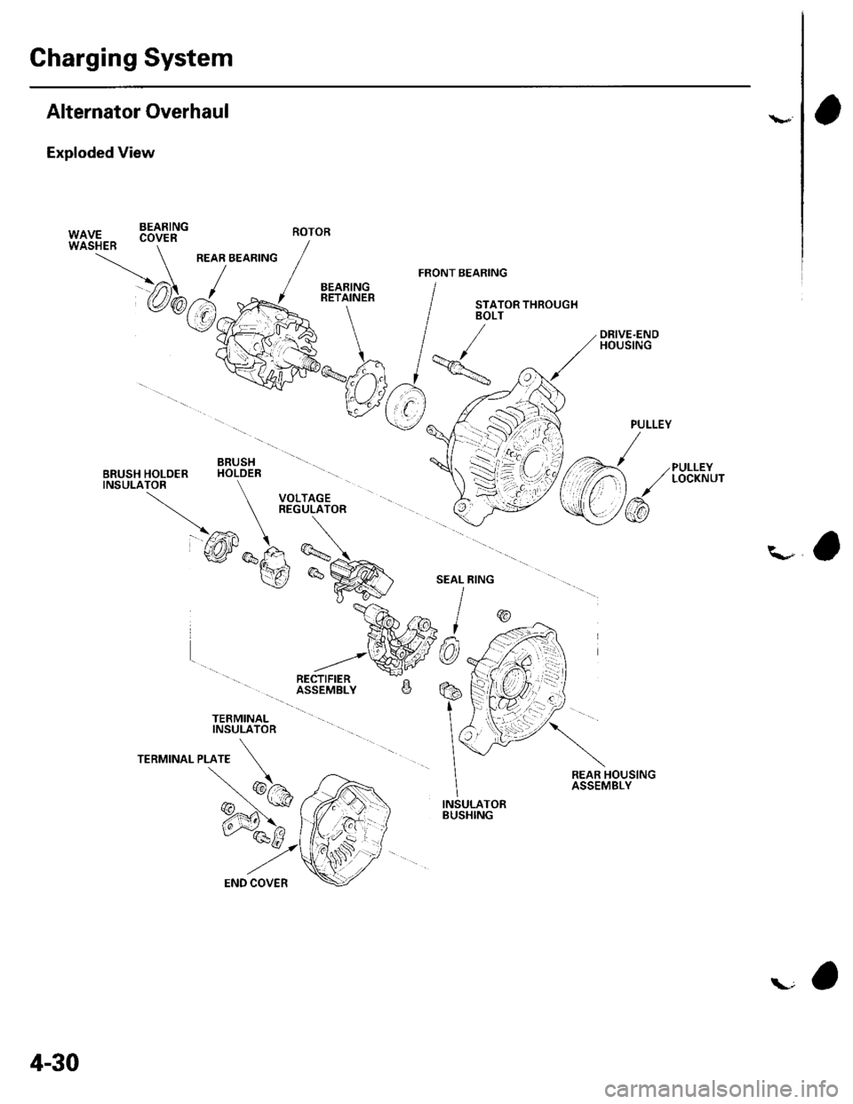
Charging System
Alternator Overhaul
Exploded View
BEARING
PULLEYLOCKNUT
\-a
TERMINALINSULATOR
REAR HOUSINGASSEMBLY
INSULATORBUSHING
PULLEY
/
\/
/@
W|UF., .oy." -
/
REAR BEARING / ,/ ./ FRoNr B
@b.J.y{=RE+LN'"'
IvVFko"-% /
qtr*njlv
V( r),
"V
BRUSH \11BRUSH HOLOER HOLDER -\
TNSULATOR \l VOLTAGE }
\-
REGULATOR (-
@*F, -\:
v_re *^i
\gP^@' I
*ffilw9
ROTOR
4-30
Page 66 of 1139
L
Special Tools Required. Driver 07749-0010000. Attachment,52 x 55 mm 07746-0010400
NOTE: Refer to the Exploded View as needed during
this procedure.
1, Test the alternator and regulator before you
remove them (see page 4-22l,.
2. Remove the alternator (see page 4-29).
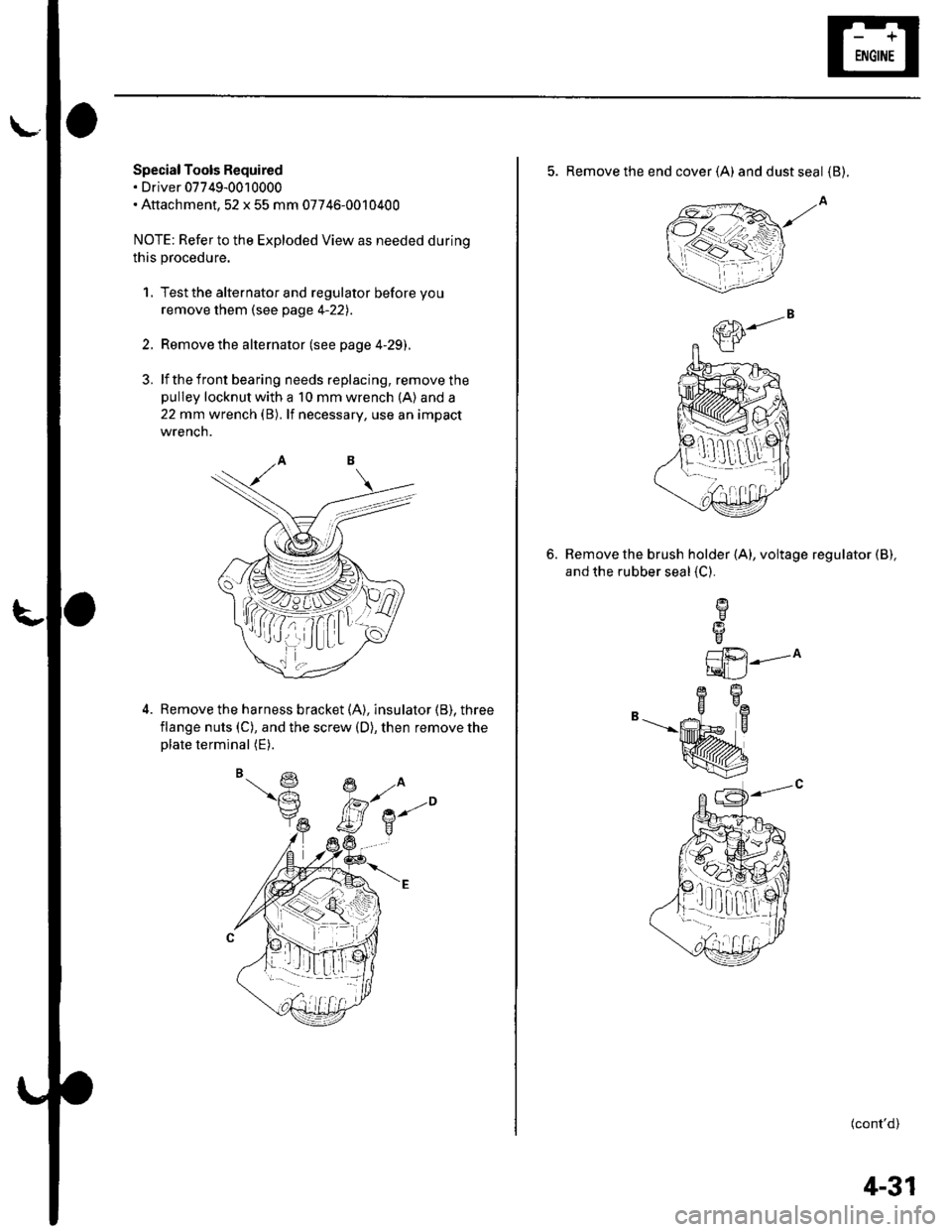
3. lf the front bearing needs replacing, remove thepulley locknut with a 10 mm wrench (A) and a
22 mm wrench (B). lf necessary, use an impact
wrencn.
Remove the harness bracket (A), insulator (B). three
flange nuts (C), and the screw (D), then remove theplate terminal (E).
,( ( , tt I;r_ lLt
5. Remove the end cover (A) anddustseal {B).
Remove the brush holder (A), voltage regulator (B),
and the rubber seal {C}.
6.
L1i.21---^
tqLJ
B-"--|.
(cont'd)
1!q[-dr,:l
4-31
Page 67 of 1139
Charging System
Alternator Overhaul (cont'dl
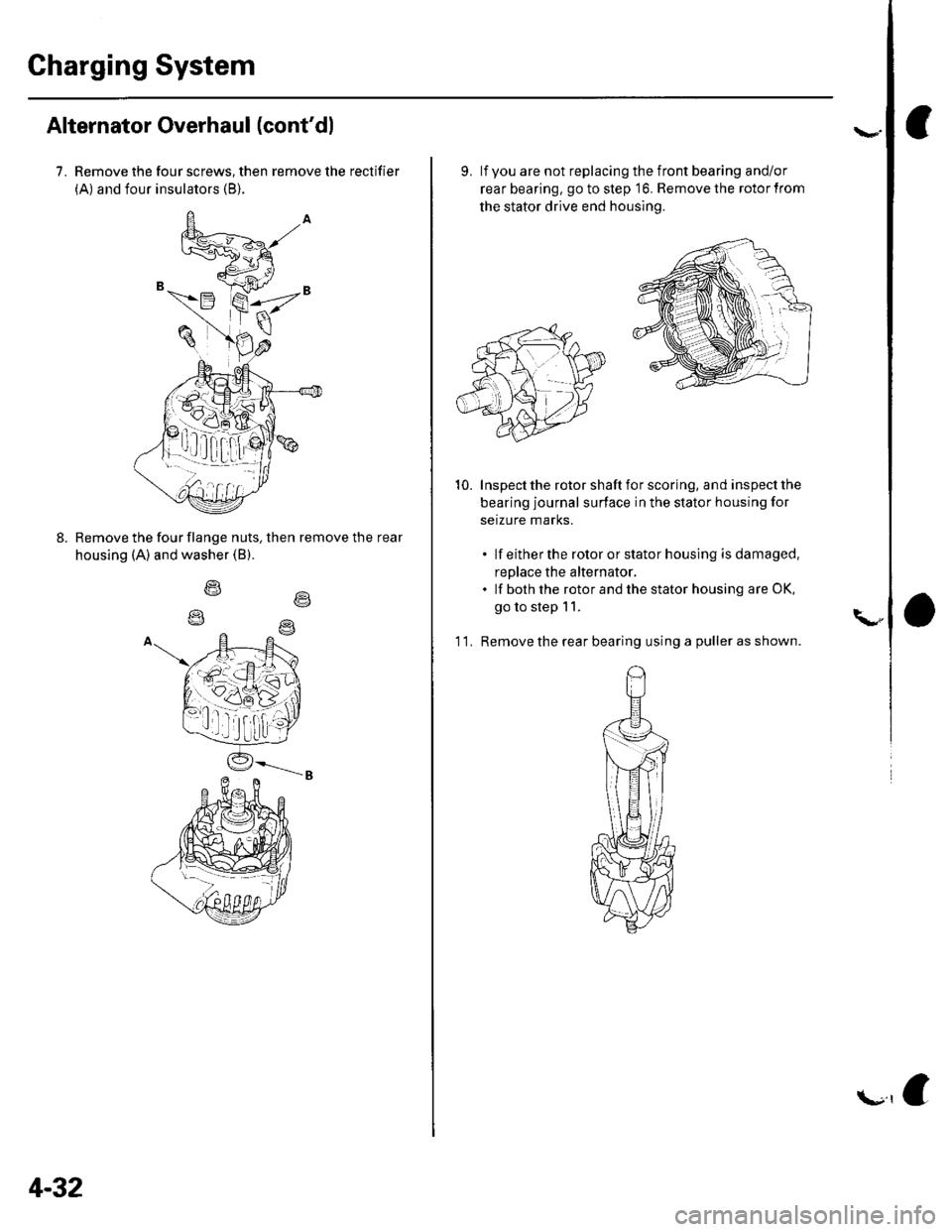
7. Remove the four screws, then remove the rectifier
(A) and four insulators (B).
Remove the four flange nuts, then remove the rear
housing (A) and washer (B).
o\
4-32
f.r,e
9. lf you are not replacing the front bearing and/or
rear bearing, go to step '16. Remove the rotor from
the stator drive end housing.
Inspect the rotor shaft for scoring, and inspect the
bearing journal surface in the stator housing for
setzure marks.
. lf eitherthe rotororstatorhousing isdamaged,
replace the alternator,. lf both the rotor and the stator housing are OK,
go to step 11.
'l 1. Remove the rear bearing using a puller as shown.
10.
\"
Page 68 of 1139
\-
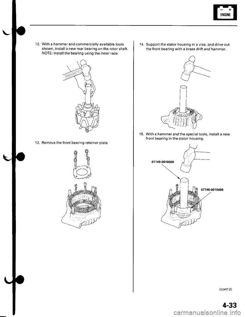
12. With a hammer and commercially available tools
shown, install a new rear bearing on the rotor shaft.
NOTE: Installthe bearing using the inner race.
13. Remove the front bearing retainer plate.
sqHE
6e
us
f-\
-:1s---'^/
14. Supportthe stator housing in a vise, and drive out
the front bearing with a brass drift and hammer.
15. With a hammer and the specialtools, install a new
front bearing in the stator housing.
07749-0010000
07746-0010400
(cont'd )
4-33
Page 69 of 1139
Charging System
Alternator Overhaul (cont'd)
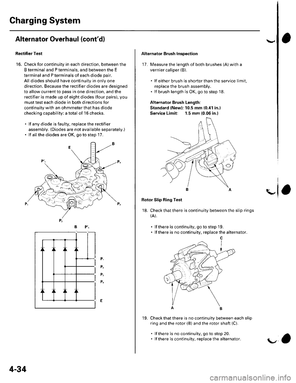
Rectitier Test
16. Check for continuity in each direction, between the
B terminal and P terminals, and between the E
terminal and P terminals of each diode pair.
All diodes should have continuity in only one
direction. Because the rectifier diodes are designed
to allow current to pass in one direction, and the
rectifier is made up of eight diodes (four pairs). you
musttest each diode in both directions for
continuity with an ohmmeter that has diode
checking capability: a total of 16 checks.
. lf any diode is faulty. replace the rectifier
assembly. {Diodes are not available separately.)' lf all the diodes are OK, go to step 17.
/--:',t- -L . --- -o \-- l'-=
BP"
P,
P.
P,
P.
4-34
19.
'a
Alternator Brush Inspection
17. Measure the length of both brushes (A)with a
vernier caliper {B).
. lf either brush isshorterthanthe service limit,
replace the brush assembly.. lf brush length is OK, go to step '18.
Alternator Brush Length:
Standard (New): 10.5 mm (0.41 in.)
Service Limit: 1.5 mm (0.06 in.)
Rotor Slip Bing Test
18. Check that there is continuity between the slip rings
{A).
. lf there is continuity, go to step 19.. lf there is no continuity, replacethe alternator.
Check that there is no continuity between each slip
ring and the rotor (B) and the rotor shaft (C).
. lf there is no continuity, goto step 20.. lf there is continuity, replace the alternator.
\"
Page 70 of 1139
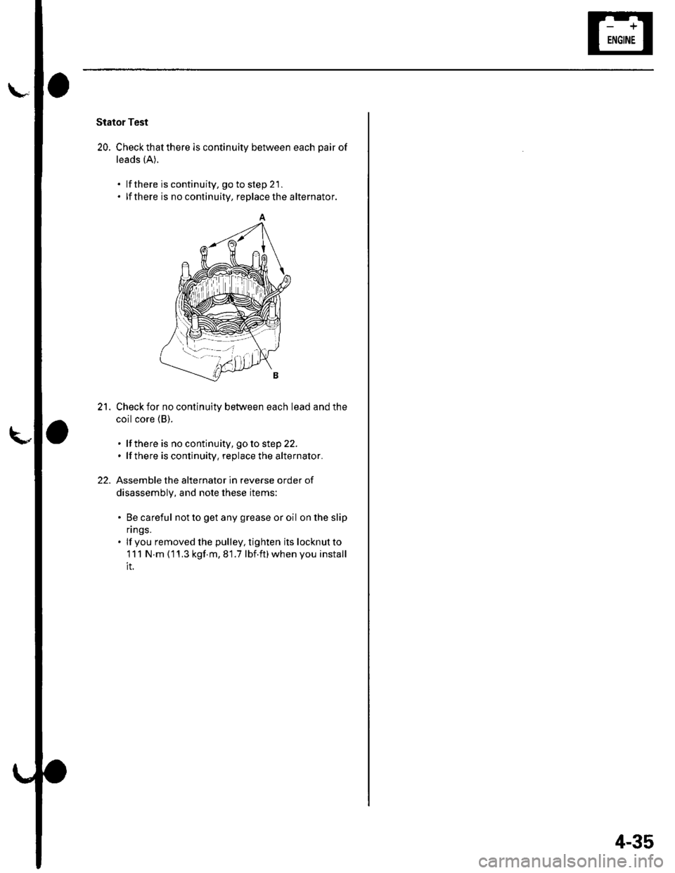
Stator Test
20. Checkthatthere is continuity between each pair of
leads (A).
lf there is continuity, go to step 21 .
lf there is no continuity, replace the alternator.
Check for no continuity between each lead and the
coil core (B).
. lf there is no continuity, goto step 22.. lfthere is continuity, replace the alternator.
Assemble the alternator in reverse order of
disassembly, and note these items:
. Be careful not to get any grease or oil on lhe slip
n ngs.. lf you removed lhe pulley, tighten its locknutto
111 N.m (11.3 kgf m,81.7 lbf.ft)whenyou install
it.
21.
22.
'--l-- --i
4-35