code HONDA CIVIC 2003 7.G Repair Manual
[x] Cancel search | Manufacturer: HONDA, Model Year: 2003, Model line: CIVIC, Model: HONDA CIVIC 2003 7.GPages: 1139, PDF Size: 28.19 MB
Page 804 of 1139
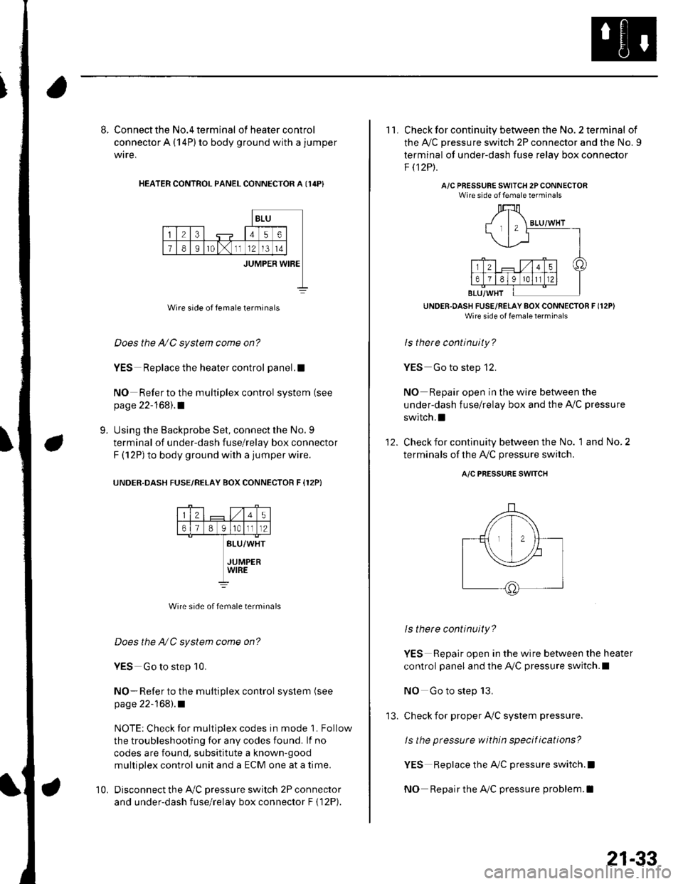
8. Connect the No.4 terminal ofheatercontrol
connector A (14P) to body ground with a jumper
wire,
HEATER CONTROL PANEL CONNECTOR A I14P}
BLU
23456
78Ir0lx1112l3t4
JUMPER WIBE
Wire side of female terminals
Does the A/C system come on?
YES Replace the heater control panel.!
NO Refer to the multiplex control system (see
page 22-168).1
Using the Backprobe Set, connect the No. 9
terminal of under-dash fuse/relay box connector
F (12P) to body ground with a jumper wire.
UNOER.DASH FUSE/RELAY BOX CONNECTOR F {12P}
9.
25
61B g lrotll2
BLU/WHT
JUMPERWIRE
Wire side of female terminals
Does the NC system come on?
YES Go to step 10.
NO- Refer to the multiplex control system (see
page 22-168).1
NOTE: Check for multiplex codes in mode '1. Follow
the troubleshooting {or any codes found. lf no
codes are found, subsititute a known-9ood
multiplex control unit and a ECM one at a time.
Disconnect the Ay'C pressure switch 2P connector
and under-dash fuse/relay box connector F { 12P).
10.
'13.
21-33
11. Check for continuity between the No. 2 terminal of
the A,/C pressure switch 2P connector and the No. 9
terminal of under-dash fuse relav box connector
F t12Pt.
A/C PRESSURE SWITCH 2PCONNECTORWire side of female terminals
UNDER.OASH FUSE/RELAY BOX CONNECTOR F (12P)
Wire side of fenale lerrrinal'
ls there continuity?
YES Go to step 12.
NO Repair open in the wire between the
under-dash fuse/relay box and the A,,/C pressure
switch.I
Check for continuity between the No. 1 and No. 2
terminals of the A,/C pressure switch.
12.
A/C PRESSURE SWITCH
ls there continuity?
YES Repair open in the wire between the heater
control panel and the A,/C pressure switch.l
NO Go to step 13.
check for proper Ay'C system pressure.
ls the pressure within specitications?
YES Replace the AilC pressure switch.l
NO Repair the AilC pressure problem.I
Page 810 of 1139
Dust and Pollen Filter Replacement
The dust and pollen filters should be replaced every
30,000 miles (48.000 km) or 24 months whichever
comes first. Replace the filters more often if the air flow
is less than usual.
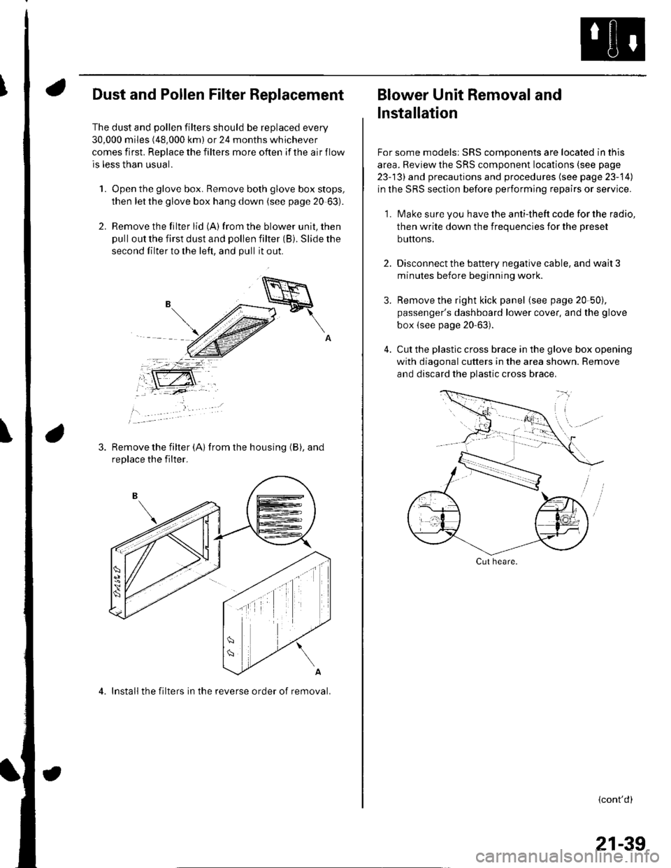
1. Open the glove box. Remove both glove box stops,
then let the glove box hang down (see page 20 63).
2. Remove the filter lid (A)from the blower unit, then
pull out the first dust and pollen filter (B). Slide the
second filter to the left, and pull it out.
Remove the filter {A) from the housing (B), and
replace the filter.
4. Install the filters in the reverse order of removal.
Blower Unit Removal and
lnstallation
For some models: SRS components are located in this
area. Review the SRS component locations (see page
23-13) and precautions and procedures (see page 23-14)
in the SRS section before performing repairs or service.
1. Make sure you have the anti-theft code for the radio,
then write down the frequencies for the preset
buttons.
2. Disconnect the battery negative cable, and wait 3
minutes before beginning worK.
3. Remove the right kick panel (see page 20-50),
passenger's dashboard lower cover, and the glove
box {see page 20-63).
4. Cut the plastic cross brace in the glove box opening
with diagonal cutters in the area shown. Remove
and discard the plastic cross brace,
Cut heare.
{cont'd)
21-39
Page 811 of 1139
Heating and Air Gonditioning
Blower Unit Removal and Installation {cont'd}
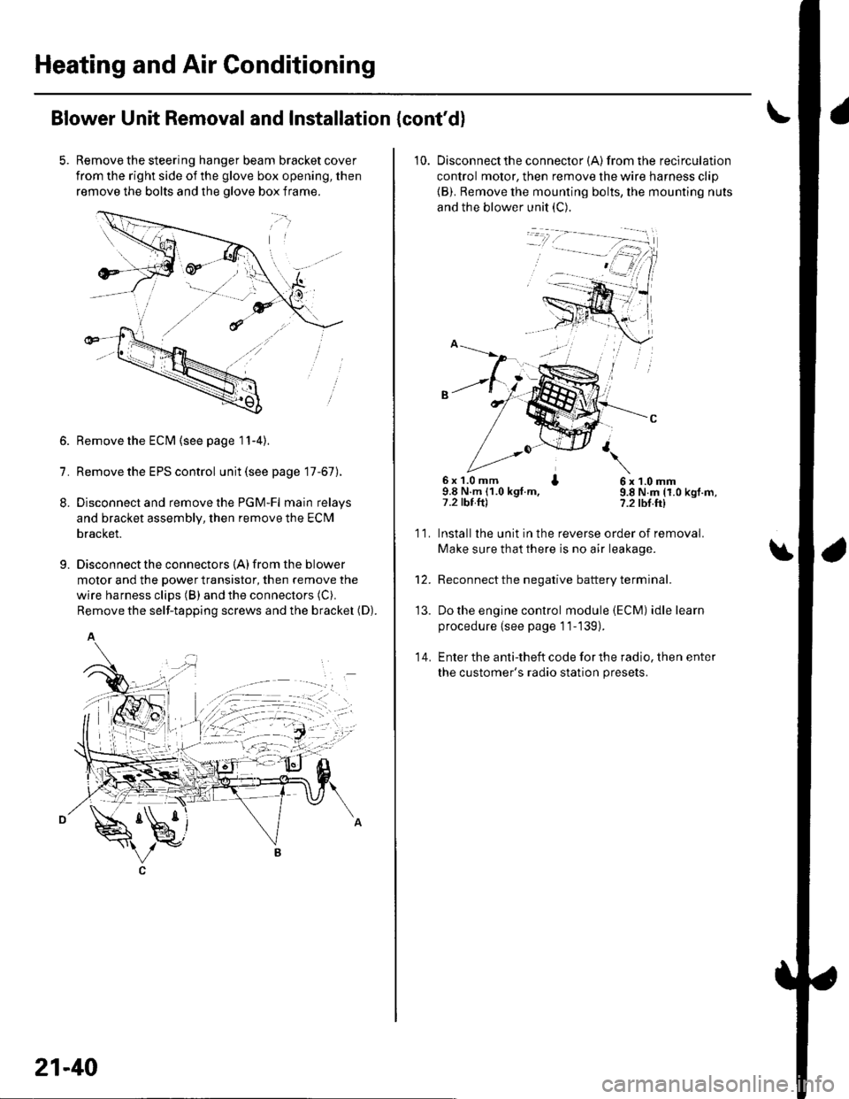
Remove the steering hanger beam bracket cover
from the right side of the glove box opening, then
remove the bolts and the olove box frame.
1.
8.
9.
Remove the ECM (see page 11-4).
Remove the EPS control unit (see page 17-67).
Disconnect and remove the PGM-Fl main relays
and bracket assembly, then remove the ECM
bracket.
Disconnect the connectors {A) from the blower
motor and the power transistor, then remove the
wire harness clips (B) and the connectors (C).
Remove the self-tapping screws and the bracket (D).
A
21-40
10. Disconnectthe connector {A) from the recirculation
control motor, then remove the wire harness clip
{B). Remove the mounting bolts, the mounting nuts
and the blower unit (C).
6x 1.0 mm I9.8 N.m (1.0 kgt.m,7.2 tbt.ftl
6x1.0mm9.8 N.m (1.0 kgf.m,?.2 tbf.ft)
11.
14.
Installlhe unit in the reverse order of removal.
Make sure that there is no air leakage.
Reconnect the negative battery terminal.
Do the engine control module (ECM) idle learn
procedure {see page 11-139).
Enter the anti-theft code for the radio, then enter
the customer's radio station presets.
\
'13.
Page 814 of 1139
Heater Unit/Core Replacement
SRS components are located in this area. Review the
SRS component locations (see page 23'13), and
precautions and procedures (see page 23-14) in the SRS
section before performing repairs or service.
1. Make sure you have the anti-theft code forthe radio,
then write down the freouencies for the radio's
Dreset buttons.
4.
Disconnect the negative cable from the battery,
Disconnect the suction and receiver lines from the
evaporator core (see page 21-42).
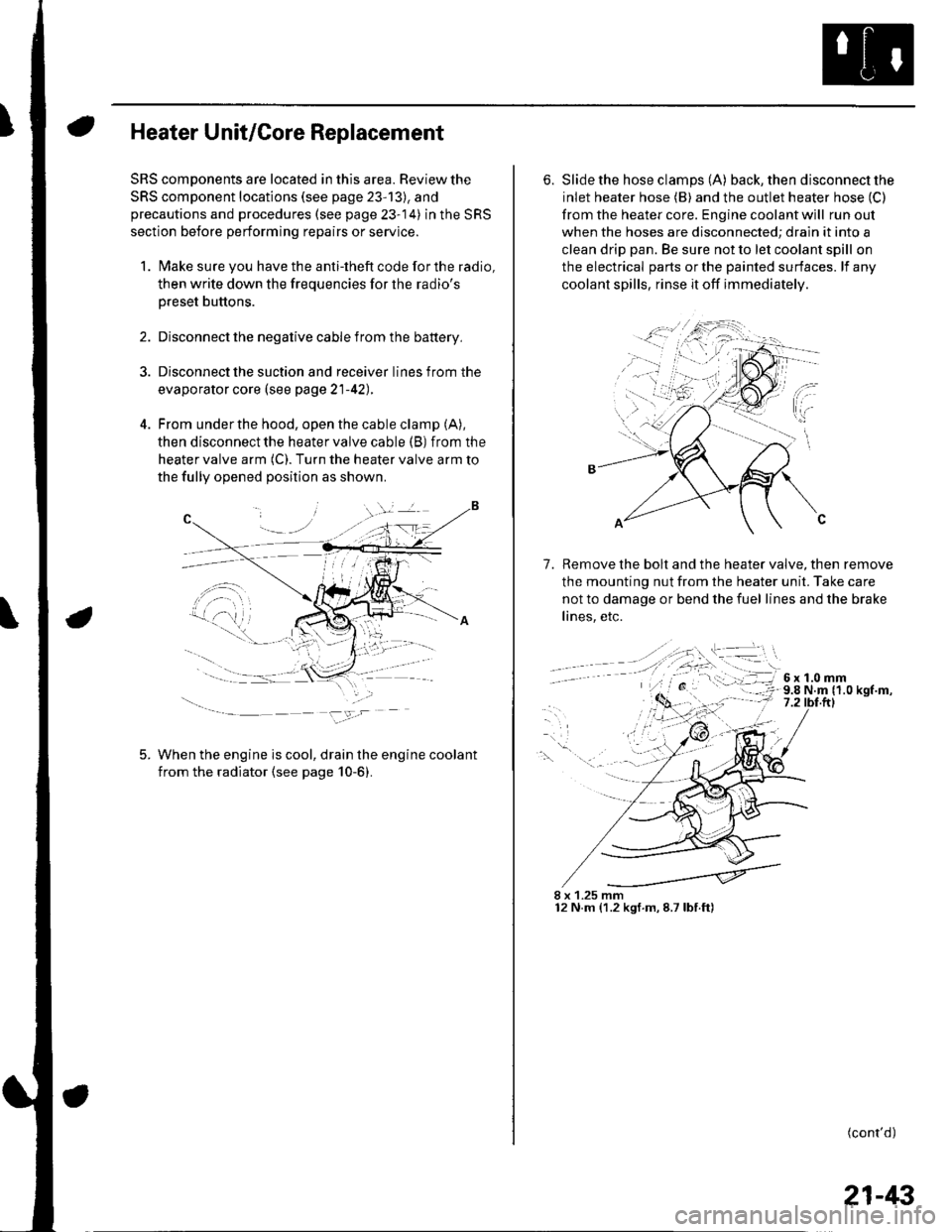
From under the hood, open the cable clamp (A),
then disconnect the heater valve cable (B) from the
heater valve arm (C). Turn the heater valve arm to
the fully opened position as shown
When the engine is cool, drain the engine coolant
from the radiator (see page 10-6).
6. Slide the hose clamps (A) back, the n d isconnect the
inlet heater hose (B) and the outlet heater hose (C)
from the heater core. Engine coolant will run out
when the hoses are disconnected; drain it into a
clean drip pan. Be sure not to let coolant spill on
the electrical parts or the painted surfaces. lf any
coolant spills, rinse it off immediately.
Remove the bolt and the heater valve, then remove
the mounting nut from the heater unit. Take care
not to damage or bend the fuel lines and the brake
lines, etc.
7.
8 x 1.25 mm12 N.m (1.2 kgf.m,8.7lbf.ft)
(cont'd)
21-43
Page 816 of 1139
13. Installthe heater core and the evaporator core in
the reverse order of removal.
14. Installthe heater unit in the reverse order of
removal, and note these items:
. Do not interchange the inlet and outlet heater
hoses, and installthe hose clamps securely.. Refillthe cooling system with engine coolant (see
page 10-6).. Adjust the heater valve cable (see page 2'l-461.. Make sure that there is no coolant leakage.. Make sure that there is no air leakage.. Refer to evaporator core replacement {see step 6
on page 21-42).. Do the engine control module (ECl\4) idle learn
procedure (see page 11-139).. Enter the anti-theft code for the radio, then enter
the customer's radio station Dresets.
21-45
Page 818 of 1139
Compressor Replacement
1. lf the compressor is marginally operable, run the
engine at idle speed, and let the air conditioning
work for a few minutes, then shut the engine off.
2. Make sure you have the anti-theft code for the radio,
then write down the frequencies for the radio's
preset buttons.
3. Disconnect the negative cable from the battery.
4. Recover the refrigerant with a recovery/recycling/
charging station (see page 21-53).
5. Remove the alternator (see page 4-29).
6. Remove the Ay'C condenser fan assembly (see page
10-10).
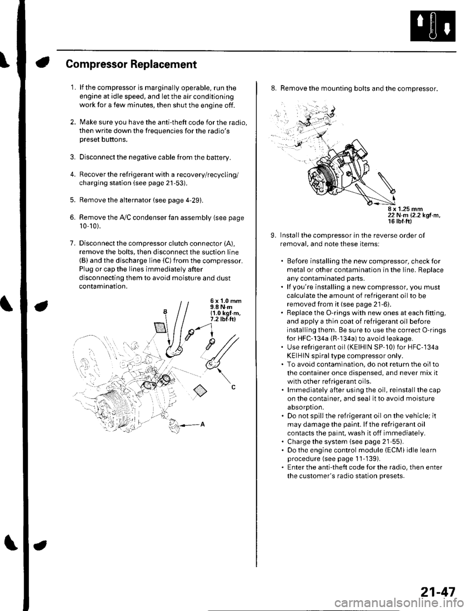
7. Disconnectthe compressor clutch connector (A),
remove the bolts, then disconnect the suction line(B) and the discharge line (C)from the compressor.
Plug or cap the lines immediately after
disconnecting them to avoid moisture and dust
contamination.
6 x '1.0 mm9.8 N.m11.0 kgt.m,7.2 tbl.ttl
u1/
(
o
8. Remove the mounting bolts and the compressor.
8 x 1.25 mm22 N.m 12.2 kgf.m.
9. Installthe compressor in the reverse order of
removal, and note these items:
. Before installing the new compressor, check for
metal or other contamination in the line. Replace
any contaminated parts.. lf you're installing a newcompressor, you must
calculate the amount of refrigerant oil to be
removed from it (see page 21-6).. Replace the O-rings with new ones at each fitting,
and apply a thin coat of refrigerant oil before
installing them. Be sure to use the correct O-rings
for HFC-134a {R-134a) to avoid leakage,. Use refrigerant oil (KElHlN SP-'10) for HFC-134a
KEIHIN spiral type compressor only.. To avoid contaminatlon, do not return the oilto
the container once dispensed, and never mix it
with other refrigerant oils.. lmmediately after using the oil, reinstallthe cap
on the container, and seal it to avoid moisture
absorption.. Do not spill the refrigerant oil on the vehicle; it
may damage the paint. lf the refrlgerant oil
contacts the paint, wash it off immediately.. Charge the system (see page 21-55).. Do the engine control module (ECM) idle learn
procedure (see page 11-'139).. Enter the antitheft code for the radio, then enter
the customer's radio station presets.
21-47
Page 837 of 1139
Body Electrical
General Troubleshooting Information (cont'dl
Five-step Troubleshooting
'1. Verify The Complaint
Turn on allthe components in the problem circuit
to verify the customer complaint. Note the
symptoms. Do not begin disassembly or testing
until you have narrowed down the problem area.
2. Analyze The Schematic
Look up the schematic for the problem circuit.
Determine how the circuit is supposed to work by
tracing the current paths from the power feed
through the circuit components to ground. lf
several circuits fail at the same time, the fuse or
ground is a Iikely cause.
Based on the symptoms and your understanding of
the circuit operation, identify one or more possible
causes of the problem.
3. lsolate The Problem By Testing The Circuit
Make circuit tests to check the diagnosis you made
in step 2. Keep in mind that a logical, simple
procedure is the key to efficient troubleshooting.
Test for the most likely cause of failure first, Try to
make tests at points that are easily accessible.
4. Fix The Problem
Once the specific problem is identified. make the
repair. Be sure to use proper tools and safe
proceoures.
5. Make Sure The Circuit Works
Turn on all components in the repaired circuit in all
modes to make sure you've fixed the entire
problem. lf the problem was a blown fuse, be sure
to test all of the circuits on the fuse. Make sure no
new problems turn up and the original problem
does not recur.
22-6
Wire Color Codes
The following abbreviations are used to identify wire
colors in the circuit schematics:
wHT....................,.,.............
YEL......................,,.......,......
B1K......................................
BLU ....,................................
GRN.....................................
RED ....................................,
oRN.....................................
PNK..........................,..........
BRN.....................................
GRY....................................,
PUR.....................................
1T81U..........................,.....
1TGRN...........................,...
White
Yellow
Black
Blue
Green
Red
Orange
Pink
Brown
Gray
Purple
Light Blue
Light Green
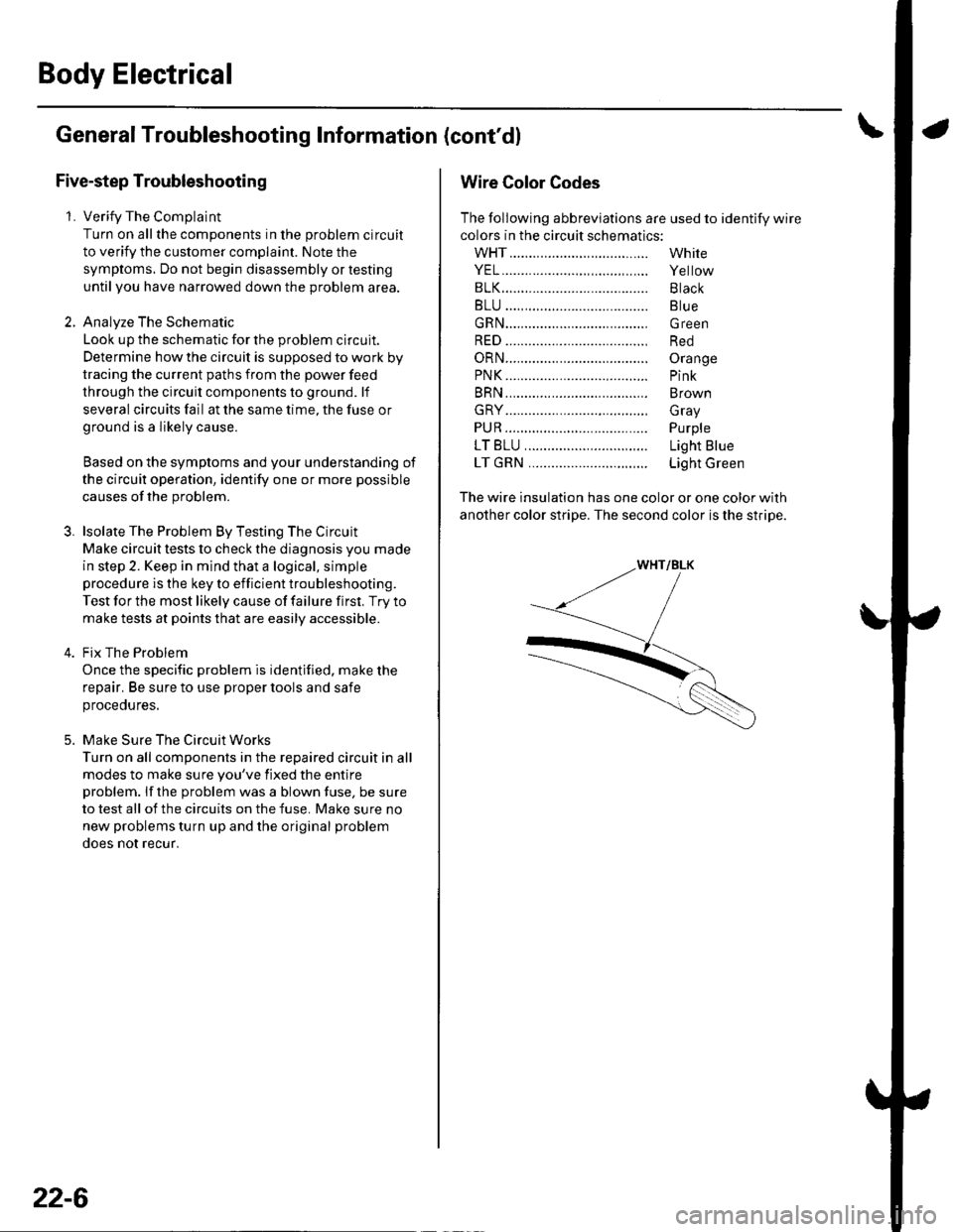
The wire insulation has one color or one color with
another color stripe. The second color is the stripe.
Page 880 of 1139
Under-dash Fuse/Relay Box
Removal and Installation
SRS components are located in this area. Review the
SRS component locations {see page 23-13) andprecautions and procedures (see page 23-14) in the SRS
section before performing repairs or service.
Removal
1. Make sure you have the anti-theft code for the radio,
then write down the frequencies for the radio's
preset buttons.
2. Disconnectthe battery negative cable, then
disconnect the positive cable, and wait at least
three minutes.
3. Remove the driver's dashboard lower cover (see
page 20-59).
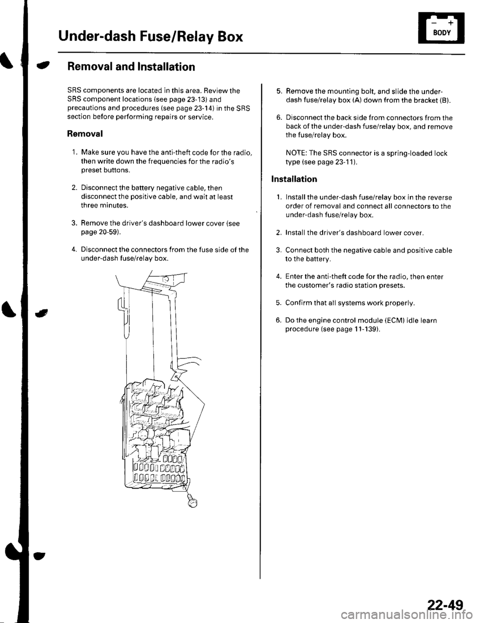
4. Disconnect the connectors from the fuse side of the
under-dash fuse/relay box.
5. Remove the mounting bolt, and slide the under-
dash fuse/relay box (A) down from the bracket {B).
6. Disconnect the back side from connectors from the
back of the under-dash fuse/relay box, and remove
the fuse/relay box.
NOTE:The SRS connector is a spring-loaded lock
type (see page 23-1 1).
lnstallation
1. Installthe under-dash fuse/relay box in the reverse
order of removal and connect all connectors to the
under-dash fuse/relay box.
2. Installthe driver's dashboard lower cover.
3. Connect both the negative cable and positive cable
to the battery.
4. Enter the anti-theft code for the radio, then enter
the customer's radio station presets.
5. Confirm that all systems work properly,
6. Do the engine control module (ECM) idle learn
procedure (see page 11-139).
22-49
Page 931 of 1139
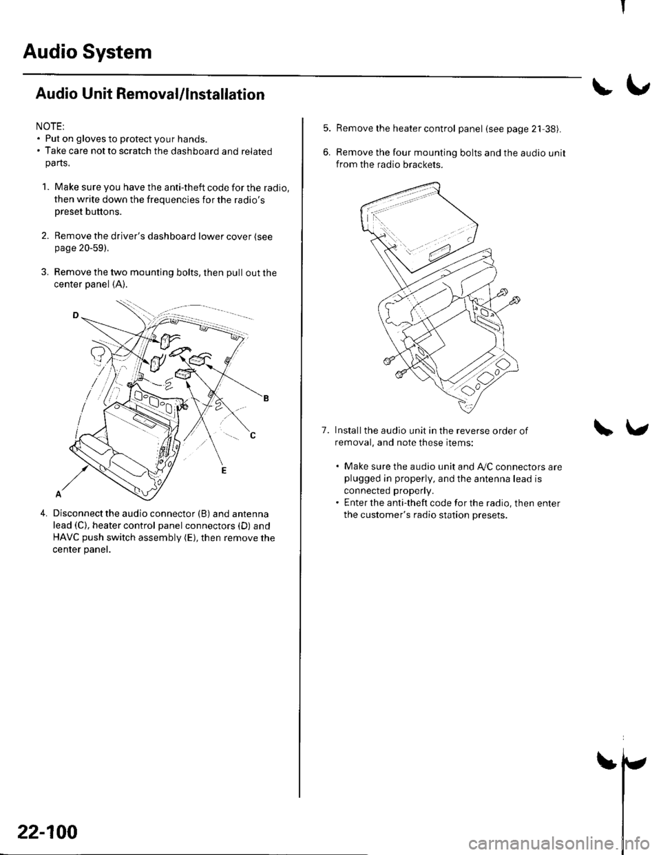
Audio System
Audio Unit Removal/lnstallation
NOTE:. Put on gloves to protect your hands.. Take care not to scratch the dashboard and relatedpa rts.
1. Make sure you have the anti-theft code for the radio,
then write down the frequencies for the radio's
preset buttons.
2. Remove the driver's dashboard lower cover (see
page 20-59).
3. Remove the two mounting bolts, then pull out the
center panel (A).
4.Disconnect the audio connector (B) and antenna
lead (C), heater control panel connectors (D) and
HAVC push switch assembly (E), then remove the
center panel.
22-100
!\,
7.
Remove the heater control panel (see page 21 38).
Remove the four mounting bolts and the audio unit
from the radio brackets.
Installthe audio unit in the reverse order of
removal, and note these items:
. Make sure the audio unit and A/C connectors areplugged in properly, and the antenna lead is
connected properly.. Enter the anti-theft code for the radio, then enter
the customer's radio station presets.
\v
I
Page 992 of 1139
Transmitter Test
NOTE:. lf the doors unlockorlockwiththetransmitter, but
the LED on the transmitter does not come on, the LED
is faulty. Replace the transmitter,. lf anydoor isopen, you cannotlockthedoorwiththe
transmrtter.. lf you unlocked the doors with the transmitter, but do
not open any of the doors within 30 seconds, the
doors relock automatically.. The doors do not lock or unlock with the transmitter if
the ignition key is inserted in the ignition switch.
1. Press the lock or unlock button five or six times to
reset the transmitter.
. lf the locks work, the transmitter is OK.. lf the locks don't work, go to step 2.
2. Open the transmitter and check for water damage.
. lf you find any water damage, replace the
transmrtter.. lf there is no waterdamage, go to step 3.
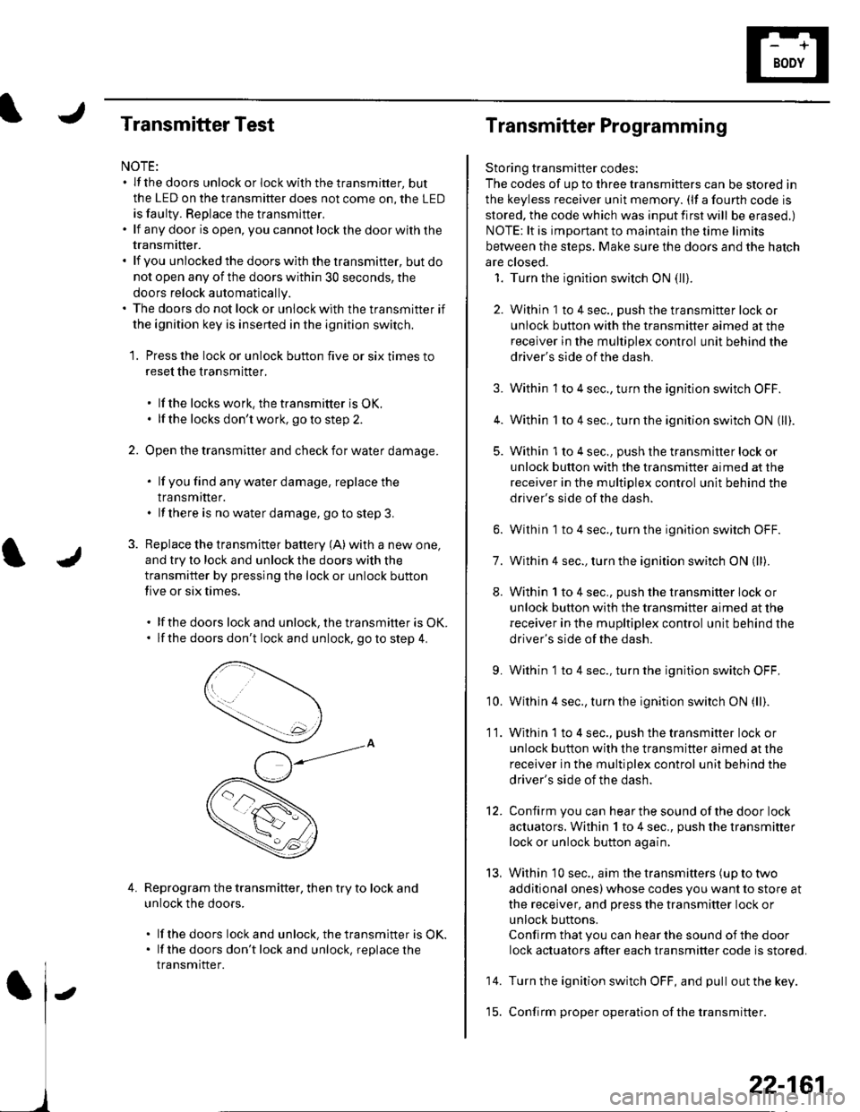
3. Replace the transmitter battery (A) with a new one,
and try to lock and unlock the doors with the
transmitter by pressing the lock or unlock button
five or six times.
. lf the doors lock and unlock, the transmifter is OK.. lf the doors don't lock and unlock, go to step 4.
Reprogram the transmitter, then try to lock and
unlock the doors.
. lf thedoors lockand unlock.thetransmitter is OK.. lf the doors don'tlockand unlock, replacethe
transmitter.
4.
Transmitter Programming
Storing transmitter codes:
The codes of up to three transmitters can be stored in
the keyless receiver unit memory. (lf a fourth code is
stored. the code which was input first will be erased.)
NOTE: lt is important to maintain the time limits
between the steps. Make sure the doors and the hatch
are closed.
1. Turn the ignition switch ON (lli.
2. Within 1 to 4 sec., push the transmitter lock or
unlock button with the transmitter aimed at the
receiver in the multiplex control unit behind the
driver's side of the dash.
3. Within 1 to 4 sec., turn the ignition switch OFF.
4. Within 1 to 4 sec., turn the ignition switch ON (ll).
5. Within 'l to 4 sec., push the transmitter lock or
unlock button with the transmitter aimed at the
receiver in the multiplex control unit behind the
driver's side of the dash.
6. Within 1 to 4 sec., turn the ignition switch OFF.
7. Within 4 sec., turn the ignition switch ON (ll).
8. Within 1 to 4 sec., push the transmitter lock or
unlock button with the transmifter aimed at the
receiver in the mupltiplex control unit behind the
driver's side of the dash.
9. Within 1 to 4 sec., turn the ignition switch OFF,
'10. Within 4 sec., turn the ignition switch ON (ll).
11. Within 1 to 4 sec., push the transmitter lock or
unlock button with the transmitter aimed at the
receiver in the multiplex control unit behind the
driver's side of the dash.
12. Confirm you can hearthe sound ofthe door lock
actuators. Within 1 to 4 sec., push the transmitter
lock or unlock button again,
13, Within 10 sec., aim the transmitters (up to two
additional ones) whose codes you want to store at
the receiver, and press the transmitter lock or
unlock buttons.
Confirm that you can hear the sound of the door
lock actuators after each transmitter code is stored.
14. Turn the ignition switch OFF, and pull out the key.
'15. Confirm proper operation ofthe transmitter.
22-161