code HONDA CIVIC 2003 7.G Repair Manual
[x] Cancel search | Manufacturer: HONDA, Model Year: 2003, Model line: CIVIC, Model: HONDA CIVIC 2003 7.GPages: 1139, PDF Size: 28.19 MB
Page 537 of 1139
EPS Components
DTC Troubleshooting (cont'd)
DTC 69: EPS Control Unit Internal Circuit
1. Clear the DTC.
2. Start the engine.
3. Turn the steering wheel from lock-to-lock several
times, and wait 10 seconds or more,
Does the EPS indicator come on?
YES Go to step 4.
NO-Check for loose wires or poor connections. lf
the connections are good, the system is OK at this
time.l
4. Stop the engine, and verify the DTC.
ls DTC 69 indicated?
YES-Check for loose or poor connections at the
EPS control unit. lf the connections are good,
substitute a known-good EPS control unit. lf the
symptom/indication goes away, replace the
original EPS control unit and recheck.l
NO- Perform the appropriate troubleshooting for
the code indicated.l
17-46
Page 540 of 1139
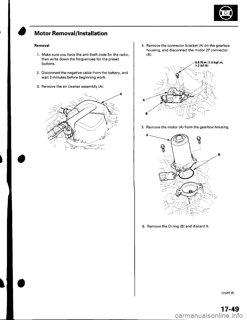
Motor Removal/lnstallation
Bemoval
1. Make sure you have the anti-theft code for the radio,
then write down the frequencies for the preset
buttons.
2. Disconnect the negative cable from the battery, and
wait 3 minutes before beginning work.
3. Remove the air cleaner assembly (A).
4. Remove the connector bracket (A) onthegearbox
housing, and disconnect the motor 2P connector(B).
9.8 N.m {1.0 kgf.m,
5. Remove the motor {A) from the gearbox housing.
6. Remove the O-ring (B) and discard it.
(cont'd)
17-49
Page 541 of 1139
EPS Components
(Motor RemovaUlnstallation (cont'dl
lnsiallation
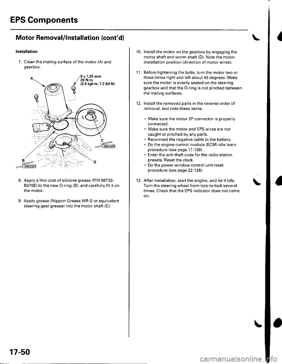
7. Clean the mating surface of the motor (A) and
gearbox.
Apply a thin coat of silicone grease (P/N 08733-
8070E)to the new O-ring (B), and carefully fit it on
the motor.
Apply grease {Nippon Grease WR-S or equivalent
steering gear grease) into the motor shaft (C).
qE
8 x '1.25 mm20 N.m12.0 kgt.m,7 .2lbl ftl
L==-c].E@
9.
17-50
r0.Install the motor on the gearbox by engaging the
motor shaft and worm shaft (D). Note the motor
installation position {direction of motor wires).
Before tightening the bolts, turn the motor two or
three times right and left about 45 degrees. lvlake
sure the motor is evenly seated on the steering
gearbox and that the O-ring is not pinched betlveen
the mating surfaces.
Installthe removed Darts in the reverse order of
removal. and note these items:
lvlake sure the motor 2P connector is properly
connected.
lvlake sure the motor and EPS wires are not
caught or pinched by any parts.
Reconnect the negative cable to the battery.
Do the engine control module (ECM) idle learn
procedure (see page 11-139).
Enter the anti-theft code for the radio station
Dresets. Reset the clock,
Do the oower window control unit reset
procedure (see page 22-1241.
After installation, start the engine, and let it idle.
Turn the steering wheel from lock-to-lock several
times. Check that the EPS indicator does not come
on.
11.
12.
13.
Page 625 of 1139
General Troubleshooting Information
ABS Indicator
. lf the system is OK,theABS indicator goes off 2
seconds after turning the ignition switch ON (ll)
without starting the engine, and then comes on again
and goes off 2 seconds later after starting the engine.
This occurs because the ABS control unitisturned
on by the lG2 power source.. The ABS indicator comes on when the ABS control
unit detects a problem in the system. However, even
though the system is operating properly, the indicator
will come on under these conditions:- Only the drive wheels rotate- One drive wheel is stuck- The vehicle goes into a spin- The ABS continues to operate for a long time.- The vehicle is subjected to an electrical signal
disturbance
To determine the actual cause of the problem, question
the customer about the problem. taking the above
condilions into consideration.
. When a Droblem is detected and lhe ABS indicator
comes on, there are cases when the indicator stays
on until the ignition switch is turned OFF, and cases
when the indicator goes off automatically when the
sYstem returns to normal.- DTC 61: The ABS indicator goes off automatically
when the system returns to normal.- DTC 11, 13,15,17 ,31,32,33, 34, 35, 36, 37, 38, 54,
or 81: The ABS indicator stays on until the ignition
switch is turned OFF whether or not the system
returns to normal.- DfC 12, 14, 16, 1a,21,51,52, or 53; The ABS
indicator goes off when the vehicle is driven again
and the system is OK after the ignition switch is
turned from OFF to ON {ll}.
Diagnostic Trouble Code {DTCI
. The memory can hold three DTCS. However, when
the same DTC is detected more than once, the more
recent DTC is written over the earlier one.
Therefore, when the same problem is detected
repeatedly, it is memorized as a single DTC.. The DTCs are in the order they occurred, beginning
with the most recent.. The DTCS are memorized in the EEPROM (non-
volatile memory). Therefore. the memorized DTCs
are not cleared when the battery is disconnected, the
ignition switch is turned off, or the system returns to
normal. Do the specified procedures to clear the
DTCs.
Self-diagnosis
. Self-diagnosis can be classified into two categories:- Initial diagnosis:
Done right after the engine starts and until the ABS
indicator goes off- Regular diagnosis:
Done rightafterthe initial diagnosis until the
ignition switch is turned OFF. When a problem is detected by self-diagnosis, the
system does the following:- Turns the ABS indicator on- Memorizes the DTC- Stops ABS control
Kickback
The pump motor operates when the ABS is functioning,
and the fluid in the reservoir is forced out to the master
cylinder, causing kickback at the brake pedal.
Pump Motor
. The pump motor operates when the ABS is
functioning.. The ABS control unit checks the pump motor
operation when the vehicle is started the first time
after the ignition switch is turned ON (ll). You may
hear the motor operate at this time, but it is normal.
(cont'd)
19-31
Page 716 of 1139
Dashboard
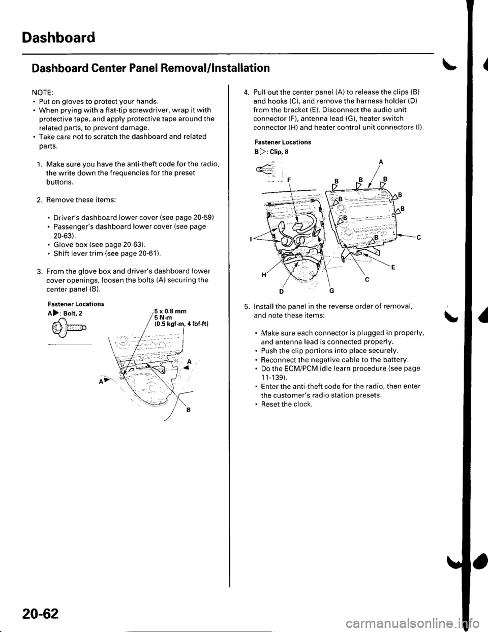
Dashboard Center Panel Removal/lnstallation
NOTE:. Put on gloves to protect your hands.. When prying with a flat-tip screwdriver, wrap it with
protective tape, and apply protective tape around the
related parts, to prevent damage.. Take care not to scratch the dashboard and related
parts.
1. Make sure you have the anti-theft code for the radio,
the write down the frequencies for the preset
buttons.
Remove these items:
. Driver's dashboard lower cover (see page 20-59)
. Passenger's dashboard lower cover (see page
20-63).. Glove box (see page 20-63).. Shift lever trim {see page 20-61).
From the glove box and driver's dashboard Iower
cover openings, loosen the bolts (A) securing the
center panel (B).
2.
Fastener Locations
A): Bolt, 2x 0.8 mm5Nm
;.'
20-62
4. Pull out the center panel (A) to release the clips (B)
and hooks (C), and remove the harness holder (D)
from the bracket (E). Disconnect the audio unit
connector (F), antenna lead (G), heater switch
connector (H) and heater control unit connectors (l).
Fastener Locations
B ): Clip, 8
Installthe panel in the reverse order of removal,
and note these items:
Make sure each connector is plugged in properly,
and antenna lead is connected properly.
Push the clip portions into place securely.
Reconnect the negative cable to the battery.
Do the ECN4/PCt\4 idle learn procedure {see page
1l-139).
Enter the anti-theft code for the radio. then enter
the customer's radio station presets.
Reset the clock.
*4
,F
\
Page 720 of 1139
Dashboard
Dashboard Removal/lnstallation
SRS components are located in this area. Review the
SRS component locations (see page 23-13) and the
precautions and procedures (see page 23-14) in the SRS
section before performing repairs or service.
NOTE:. When prying with a flat-tip screwdriver, wrap it with
protective tape, and apply protective tape around the
related parts to prevent damage.. Have an assistant help you when removing and
installing the dashboa rd.. Take care not to scratch the dashboard, body, and
other related parts.
. Put on gloves to protect your hands.
1. Make sure you have the anti-theft code for the radio,
then write down the frequencies for the preset
buttons.
Disconnect the negative cable from the battery, and
wait at least three minutes before beginning work.
Remove these items:
. Driver's dashboard lower cover (see page 20-59). Driver's dashboard under cover (see page 20-60). Passenger's dashboard lower cover (see page
20-63). Glove box (see page 20-63). Consoles, front and rear (see page 20-57). Shift lever trim {see page 20-61). Center panel (see page 20-62). Kick panels, both sides (see page 20-50). A-pillar trim. both sides (see page 20-50). Steering column (see page 17-9)
20-66
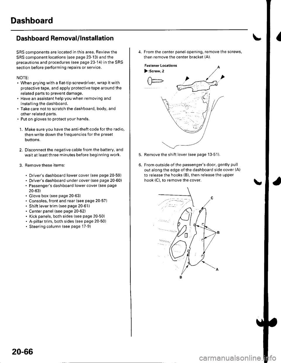
4. From the center panel opening, remove the screws,
then remove the center bracket (A).
Fastener Locations
):Screw,2
Remove the sh ift lever (see page 13-51).
From outside of the passenger's door, gently pull
out along the edge of the dashboard side cover (A)
to release the hooks (B), then release the upper
hook (C), to remove the cover.
Page 722 of 1139
Dashboard
Dashboard Removal/lnstallation
(cont'd)
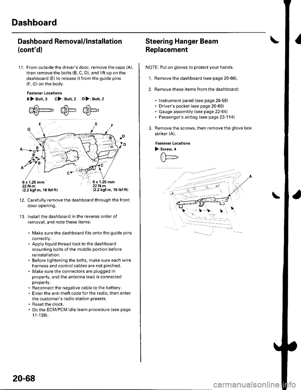
11. From outside the driver's door, remove the caps (A),
then remove the bolts (8, C, D), and lift up on the
dashboard (E) to release it from the guide pins
(F. G) on the body.
Fastener Locations
B>rBolt.3 C>: Bolt,2 D>: Bolt,2
m6[-,,,,",",,-,F6't---'' ffi'!--v{/- Kr* w-
B
$7:
^/761:
/,-,. r:; 8 x 1.25 mm22Nm(2.2 kgf.m, 16lbf.ft)
13.
{2.2 kgf m, 16lbf.ftl
Carefully remove the dashboard through the front
door opening.
lnstall the dashboard in the reverse order of
removal, and note these items:
. Make sure the dashboard fits onto the guide pins
correctly.. Apply liquid thread lock to the dashboard
mounting bolts of the middle portion before
reinstallation.. Before tightening the bolts, make sure each wire
harness and control cables are not pinched.
. Make sure the connectors are plugged in
properly, and the antenna lead is connected
propeny.. Reconnect the negative cable to the battery.. Enter the anti-theft code for the radio, then enter
the customer's radio station presets.
. Reset the clock.. Do the ECM/PCM idle learn procedure isee page
1 '1-139).
20-68
Steering Hanger Beam
Replacement
NOTE: Put on gloves to protect your hands.
1, Remove the dashboard (see page 20-66).
2. Remove these items from the dashboard:
. lnstrument panel (see page 20-59). Driver's pocket (see page 20-60). Gauge assembly (see page 22-64). Passenger's airbag (see page 23-'l 14)
Remove the screws, then remove the glove box
striker (A).
Fastenea Locations
):Screw,4
\
Page 725 of 1139
Front Seat Removal/lnstallation
For some models: SRS components are located in this
area. Review the SRS component locations (see page
23-'13) and the precautions and procedures (see page
23-14) in the SRS section before performing repairs or
service.
NOTE. When prying with a flat-tip screwdriver, wrap it with
protective tape to prevent damage.. Take care not to scratch the body or tear the seat
covers.. Put on gloves to protect your hands.
1, Make sure you have the anti-theft code for the radio,
then write down the frequencies for the preset
butlons.
Disconnect the negative cable from the battery, and
wait at least 3 minutes before beginning work.
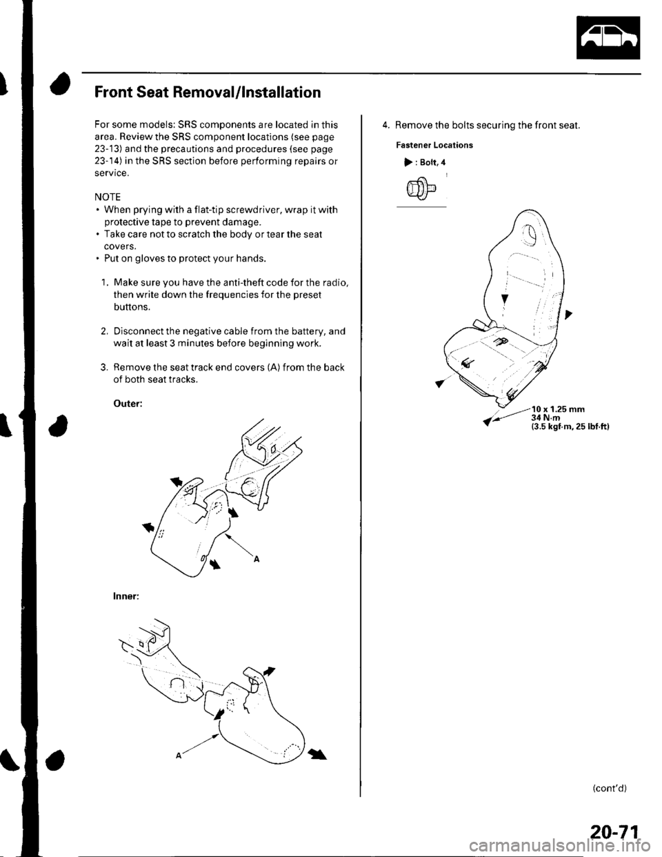
Remove the seat track end covers (A) from the back
of both seat tracks.
Outef:
lnner:
3.
\
4. Remove the bolts securing the front seat.
Fastener Locations
10 x 1.25 mm
> : Bolt,
@
(cont'd)
20-71
Page 726 of 1139
Seats
Front Seat Removal/lnstallation (cont'dl
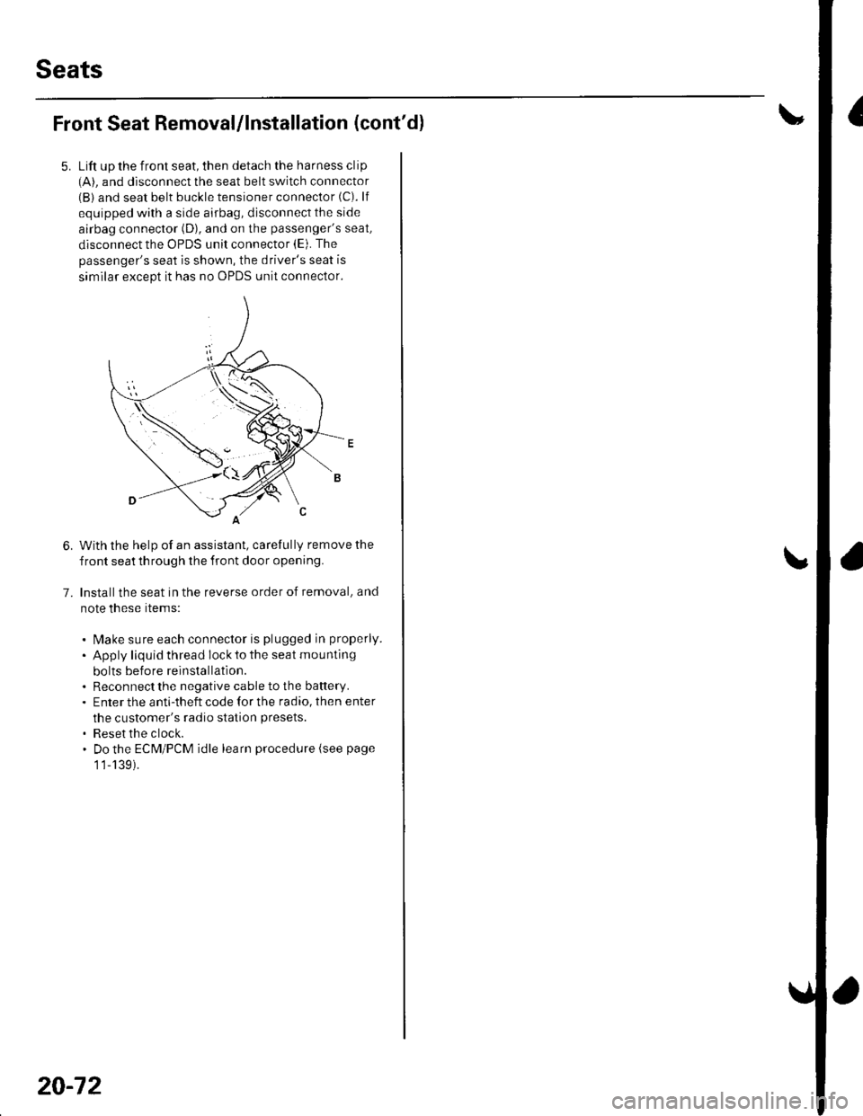
Lift up the front seat, then detach the harness clip(A). and disconnect the seat belt switch connector(B) and seat belt buckle tensioner connector (C). lf
equipped with a side airbag, disconnect the side
airbag connector (D), and on the passenger's seat,
disconnect the OPDS unit connector (E). The
passenger's seat is shown, the driver's seat is
similar except it has no OPDS unit connector.
With the help of an assistant, carefully remove the
front seat th rough the front door opening.
Installthe seat in the reverse order of removal, and
note these rtems:
. l\4ake sure each connector is plugged in properly.
. Apply liquid thread lock to the seat mounting
bolts before reinstallatlon.. Reconnect the negative cable to the battery.. Enter the anti-theft code for the radio, then enter
the customer's radio station presets.
. Reset the clock.. Do the ECM/PCM idle learn procedure (see page
1 1-139).
6.
7.
20-72
Page 780 of 1139
Heating and Air Conditioning
General Troubleshooting Information
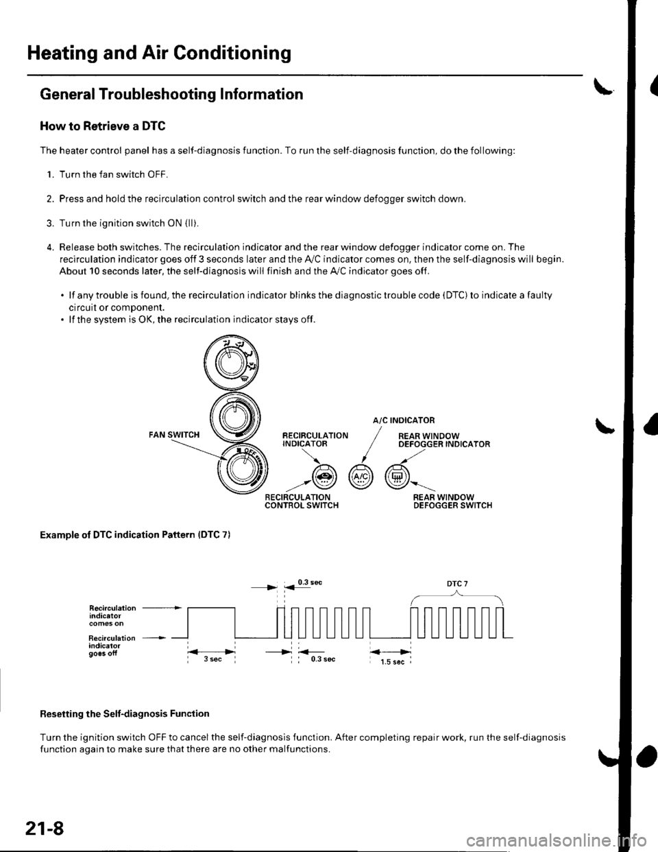
How to Retrieve a DTC
The heater control panel has a self-diagnosis function. To run the self-diagnosis function, do the following:
1. Turn the fan switch OFF.
2. Pressand holdthe recirculation control switch andthe rear window defoooer switch down.
3. Turn the ignition switch oN {lli.
4. Release both switches. The recirculation indicator and the rear window defogger indicator come on. The
recirculation indicator goes off 3 seconds later and the Ay'C indicator comes on. then the self-diagnosis will begin.
About 10 seconds later, the self-diagnosis will finish and the A,/C indicator goes off.
.lfanytroubleisfound.therecirculationindicatorblinksthediagnostictroublecode(DTC)toindicateafaulty
circuil or comDonent.. lf the system is OK, the recirculation indicator stays off.
atc
@r
RECIRCULATIONCONTROL SWITCH
BECIRCULATIONINDICATOB
/A\
-:@
INOICATOR
REAR WINDOWOEFOGGER INDICATOR
REAR WINDOWDEFOGGER SWITCH
Examole of DTC indication Pattern IDTC 7)
DTC 7
Reseiting the Selt-diagnosis Function
Turn the ignition switch OFF to cancel the self-diagnosis function. After completing repair work, run the self-diagnosis
function aoain to make sure thatthere are no other malfunctions.
Recirculation +indicatot
Recirculation +indicalorgo6s oft----->
21-8