Cruise control cable HONDA CIVIC 2003 7.G Workshop Manual
[x] Cancel search | Manufacturer: HONDA, Model Year: 2003, Model line: CIVIC, Model: HONDA CIVIC 2003 7.GPages: 1139, PDF Size: 28.19 MB
Page 36 of 1139
\.
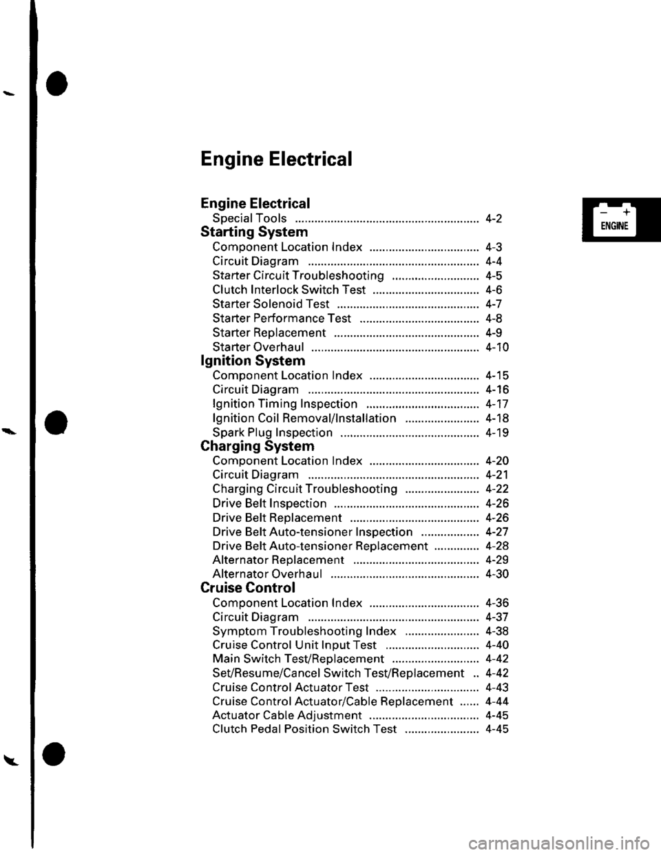
Engine Electrical
Engine Electrical
SpecialTools
Starting System
Comoonent Location Index ...............
Circuit Diagram
Starter Circu it Troubleshooting
Clutch Interlock Switch Test
Starter Solenoid Test ..............
Sta rter Performance Test
Starter Reolacement ...............
Starter Overhaul .......................
lgnition System
Component Location Index ...............
Circuit Diagram
lgnition Timing Inspection
lgnition Coil Removal/1nsta11ation .......................
Spark Plug Inspection
Charging System
Component Location Index .................................. 4-2O
Circuit Diagram ........................... 4-21
Charging Circuit Troubleshooting ....................... 4-22
Drive Belt Inspection ................... 4-26
Drive Beft Replacement .............. 4-26
Drive BeftAuto-tensioner Inspection .................. 4-27
Drive Beft Auto-tensioner Replacement .............. 4-28
Alternator Reolacement ............. 4-29
Alternator Overhaul ................ .... 4-30
Cruise Control
Component Location Index .................................. 4-36
Circuit Diagram ........................... 4-37
Symptom Troubleshooting Index ....................... 4-38
Cruise Control Unit lnDut Test ............................. 4-40
Main Switch TesVReolacement ........................... 4-42
SeVResume/Cancel Switch TesVReplacement .. 4-42
Cruise Control Actuator Test ...... 4-43
Cruise Control Actuator/Cable Replacement ...... 4-44
Actuator Cable Adjustment .................................. 4-45
Clutch Pedal Position Switch Test ....................... 4-45
4-2
4-J
4-4
4-5
4-6
4-7
4-8
4-9
4-10
4-15
4-16
4-17
4-18
4- 19
-+
ENGINE
Page 71 of 1139
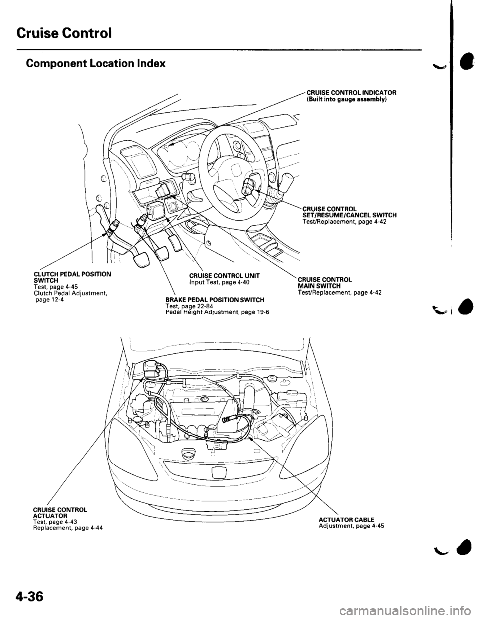
Gruise Control
Component Location Index
CLUTCH PEDAL POSITIONswtTcHTest, page 4-45Clutch Pedal Adjustment,page 12-4
t.- _,- _
CRUISE CONTROLACTUATORTest, page 4'43Replacement, page 4-44
CRUISE CONTROL UNITlnput Test, page 4-40
BRAKE PEDAL POSITION SWITCHTest, page 22-84Pedal Height Adjustment, page '19-6
CRUISE CONTROL INDICATOR(Built into gaug6 assembly)
ACTUATOR CABLEAdjustment, page 4-45
-ll
4-36
\-a
Page 76 of 1139
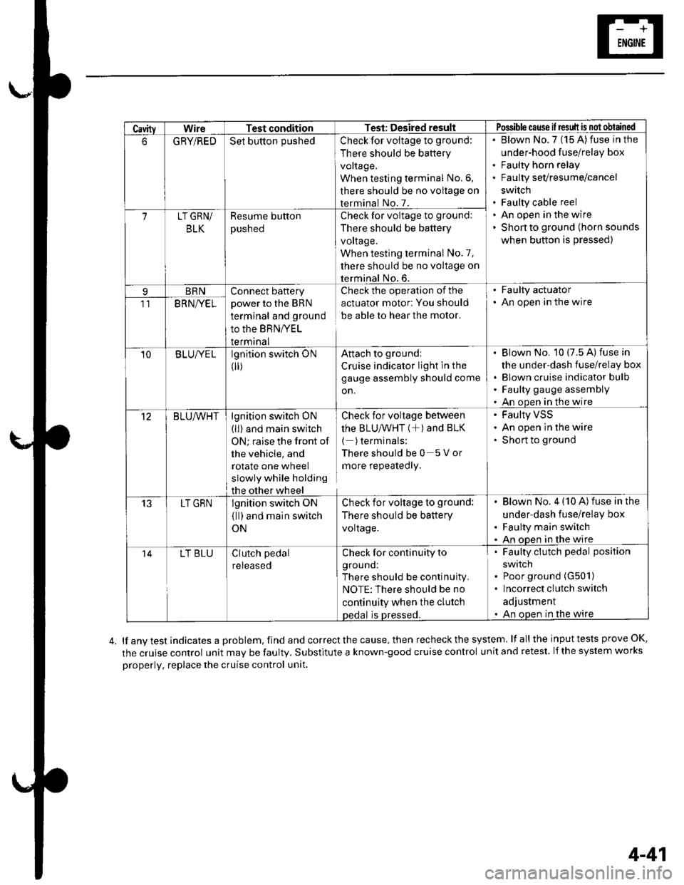
CavityWireTest conditionTest: Desired resultPossible cause il result is not obtained
6GRYiREDSet button pushedCheck for voltage to ground:
There should be battery
voltage,
When testing terminal No.6,
there should be no voltage on
terminal No. 7.
Blown No.7 (15 A)fuse in the
under-hood fuse/relay box
Faulty horn relay
Faulty sevresume/cancel
swrtch
Faulty cable reel
An open in the wire
Shon to ground (horn sounds
when button is pressed)
7LT GRN/
BLK
Resume button
pusneo
Check for voltage to ground:
There should be battery
voltage.
When testing terminal No.7,
there should be no voltage on
terminal No. 6.
BRNConnect battery
power to the BRN
terminal and ground
to the BRNIVEL
termrnal
Check the operation of the
actuator motor: You should
be able to hear the motor.
. Faulty actuator. An open in the wire11BRNI/EL
10B LUIVE Llgnition switch ON
0r)
Attach to groundi
Cruise indicator light in the
gauge assembly should come
on.
Blown No. 10 (7.5 A) fuse in
the under-dash fuse/relay box
Blown cruise indicator bulfl
Faulty gauge assembly
An open in the wire
12BLU/VVHTlgnition switch ON
(ll) and main switch
ON; raise the front of
the vehicle, and
rotate one wheel
slowly while holding
the other wheel
Check for voltage between
thE BLU/VVHT (+) ANd BLK
( )terminals:
Thereshouldbe0 5Vor
more repeatedly.
Faulty VSS
An open in the wire
Short to ground
13LT GRNlgnition switch oN
{ll) and main switch
ON
Check for voltage to ground:
There should be battery
voltage.
Blown No. 4 (10 A)fuse in the
under-dash fuse/relay box
Faulty main switch
An oDen in the wire
14LT BLUClutch pedal
reteaseo
Check for continuity to
grouno:
There should be continuity.
NOTE:There should be no
continuity when the clutch
oedal is Dressed.
Faulty clutch pedal position
swtlcn
Poor ground (G501)
Incorrect clutch switch
adjustment
An open in the wire
lf any test indicates a problem, find and correct the cause, then recheck the system. lf all the input tests prove OK,
the cruise control unit may be faulty. Substitute a known-good cruise control unit and retest. lf the system works
properly, replace the cruise control unit.
4-41
Page 79 of 1139
Cruise Control
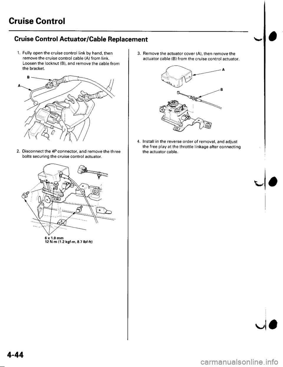
Cruise Control Actuator/Cable Replacement
1.Fully open the cruise control link by hand, then
remove the cruise control cable {A) from link.
Loosen the locknut (B), and remove the cable from
the bracket.
Disconnect the 4P connector, and remove the three
bolts securing the cruise control actuator.
2.
6x1,0mm12 N.m (1.2 kgf.m,8.7 lbf.ft)
4-44
la
3.Remove the actuator cover (A), then remove the
actuator cable (B) from the cruise control actuator.
Install in the reverse order of removal, and adjust
the free play at the throttle linkage after connecting
the actuator cable.
4.
Page 83 of 1139
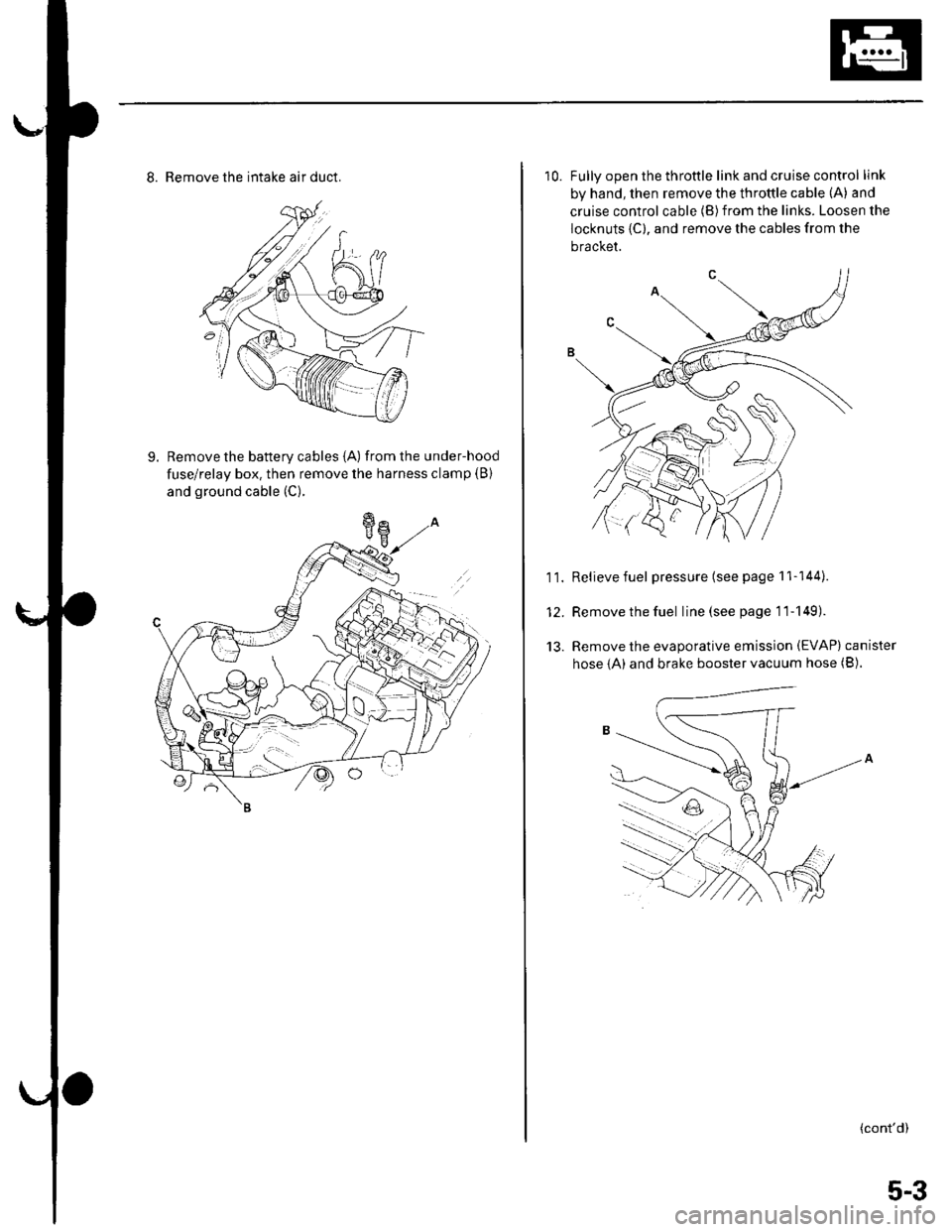
8. Remove the intake air duct.
9. Remove the battery cables {A) fromthe under-hood
fuse/relay box. then remove the harness clamp (B)
and ground cable (C).
10. Fullv ooen the throttle link and cruise control link
by hand, then remove the throttle cable (A) and
cruise control cable (B)from the links. Loosen the
locknuts {C), and remove the cables from the
bracket.
11. Relievefuel pressure (see page 11-144).
12. Remove the fuel line(seepagell-149).
13. Remove the evaporative emission (EVAP) canister
hose {A) and brake booster vacuum hose (B).
(cont'd)
5-3
Page 93 of 1139
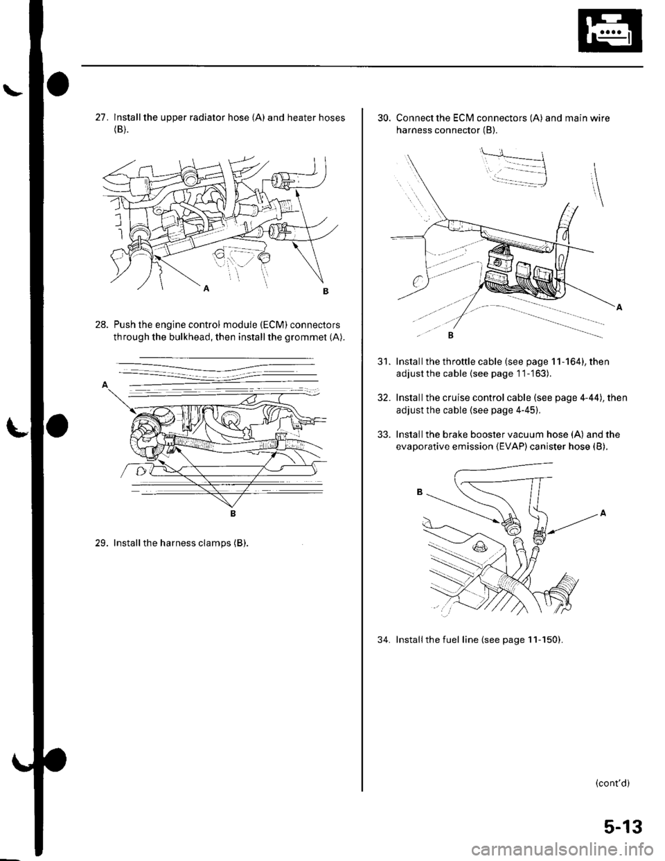
27. lnstallthe upper radiator hose {A) and heater hoses(B).
Push the engine control module (ECM) connectors
through the bulkhead, then installthe grommet (A).
29. Installthe harness clamps (B).
30. Connect the ECI\4 connectors (A) and main wire
harness connector (B).
Install the throttle cable (see page 11-164), then
adjustthe cable {see page 11-'163).
Installthe cruise control cable (see page 4-44), then
adjust the cable (see page 4-45),
Install the brake booster vacuum hose (A) and the
evaporative emission (EVAP) canister hose (B).
34. Installthe fuel line (see page 11-150).
31.
32.
33.
(cont'd)
5-13
Page 185 of 1139
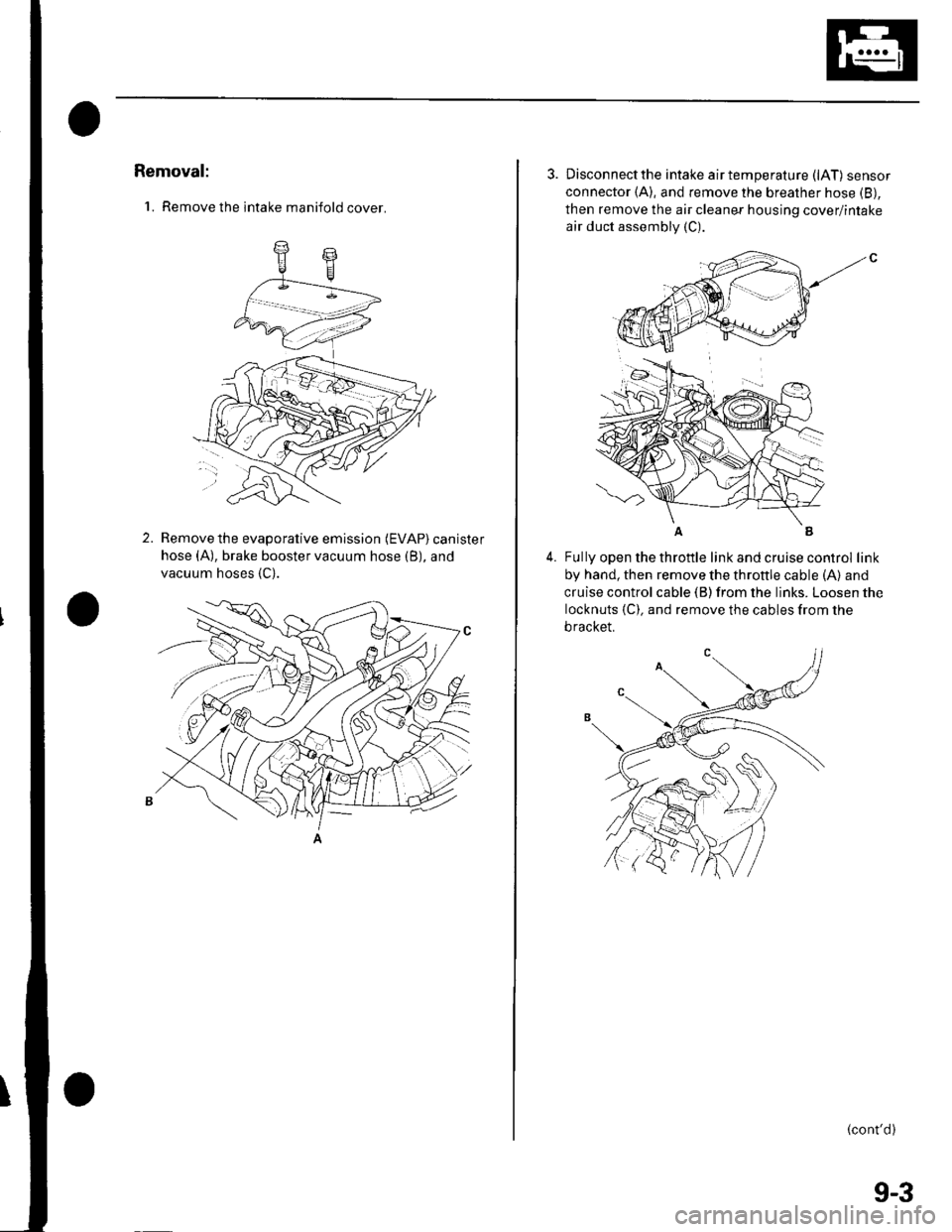
Removal:
'1. Remove the intake manifold cover.
2.Remove the evaporative emission (EVAP) canister
hose (A), brake booster vacuum hose (B), and
vacuum hoses {C).
3. Disconnectthe intake airtemperature (lAT) sensor
connector (A), and remove the breather hose (B),
then remove the air cleaner housing cover/intake
air duct assembly (C).
4.Fully open the throttle link and cruise control link
by hand, then remove the throttle cable (A) and
cruise control cable (B) from the links. Loosen the
locknuts {C). and remove the cables from the
bracket.
(cont'd)
(
9-3
Page 187 of 1139
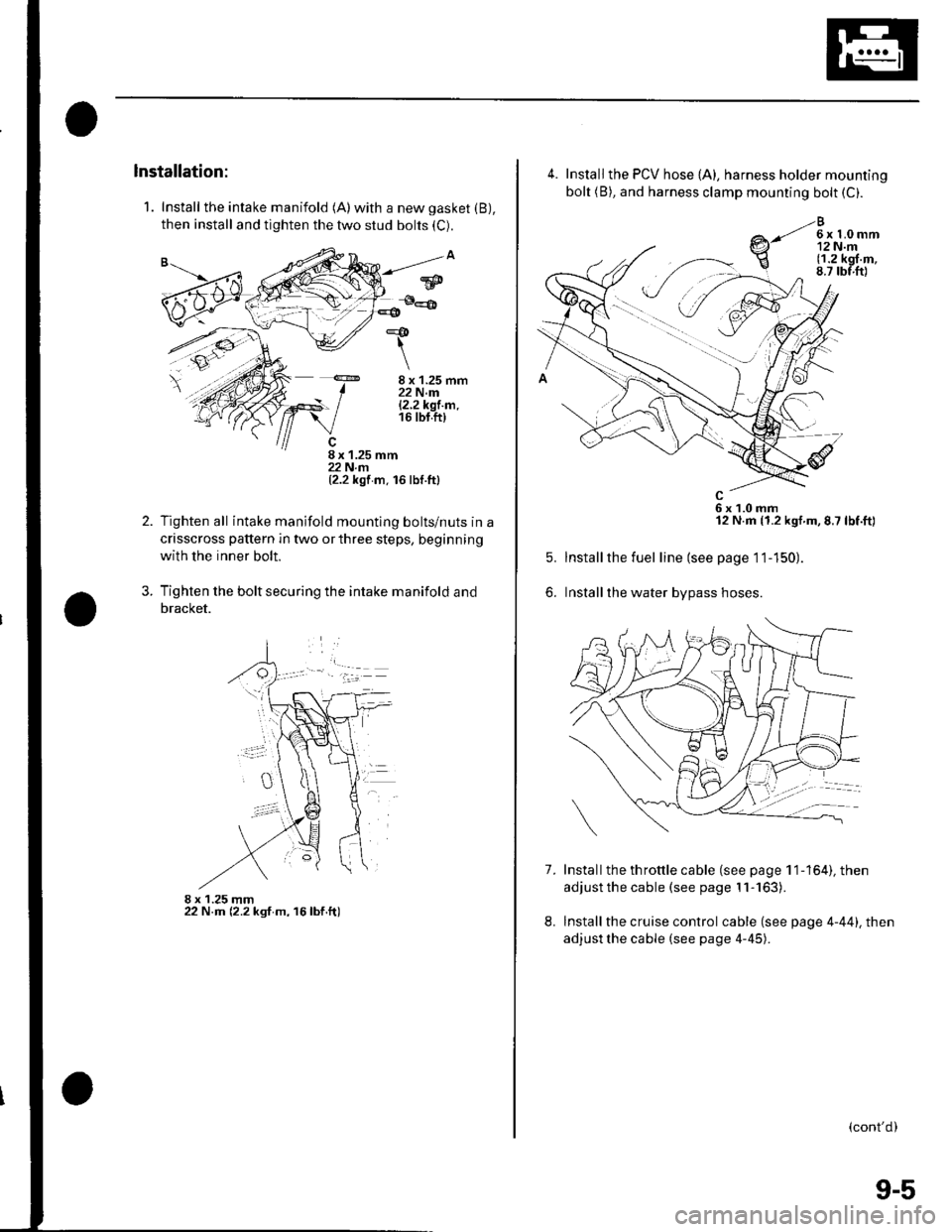
1. Install the intake manifold (A)with a new gasket (B),
then install and tighten the two stud bolts (C).
8 x 1.25 mm22 N.m|.2.2k91.m.16 tbt.ft)
8 x 1.25 mm22 N.rn(2.2 kgf m. 16 lbf.ttl
Tighten all intake manifold mountlng bolts/nuts in a
crisscross pattern in two or three steps, beginning
with the inner bolt.
Tighten the bolt securing the intake manifold and
bracket.
8 x 1.25 mm22 N.m (2.2 ksf m, 16lbf.ft)
*&
\
2.
?
w
4.
7.
5.
6.
Install the PCV hose {A), harness holder mounting
bolt (B), and harness clamp mounting bolt (C).
e-li*h,r
6x1.0mm12 N.m (1.2 kgf.m,8.7 lbf.ft)
Installthe fuel line (see page 11-150).
Installthe water bypass hoses.
Install the th rottle cable (see page 1 1-164), then
adjust the cable (see page 11-163).
Install the cruise control cable (see page 4-44). then
adjust the cable (see page 4-45).
8.
(cont'd)
9-5
Page 372 of 1139
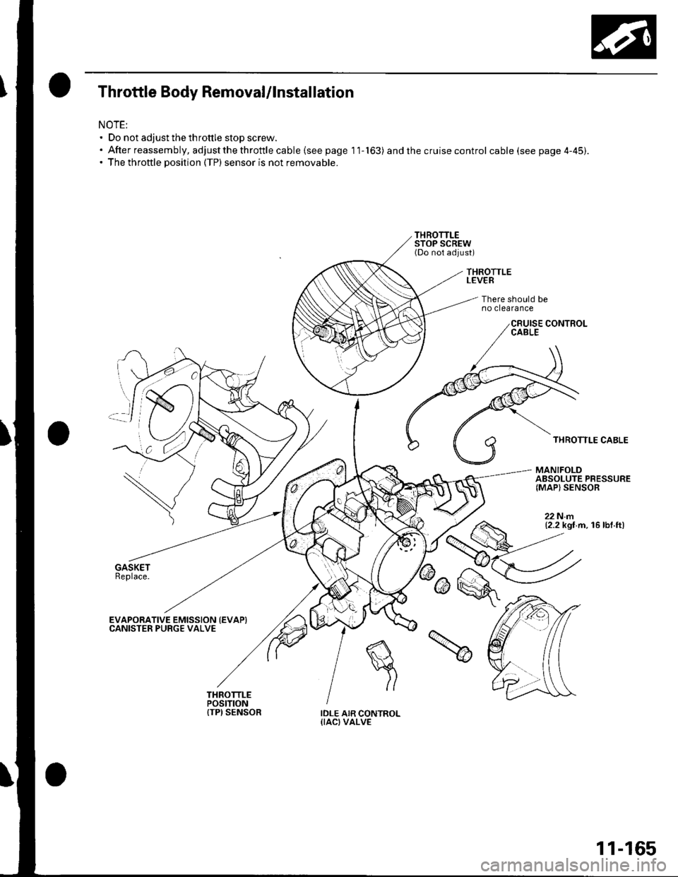
Throttle Body Removal/lnstallation
NOTE:' Do not adjust the throttle stop screw.. Afterreassembly,adjustthethrottlecable{seepagell-163) and the cruise control cable (see page 4-45).. The throttle position (TP) sensor is not removable.
THROTTLELEVER
There should beno clearance
THROTTLE CABLE
MANIFOLDABSOLUTE PRESSURE{MAP} SENSOR
22Nm(2.2 kgt.m, 16 lbf.ft)
EVAPORATIVE EMISSION {EVAPICANISTER PURGE VALVE
IDLE AIR CONTROL{IACI VALVE
11-165
Page 498 of 1139
Steering
Steering Wheel Removal
SRS components are located in this area. Review the
SRS component locations (see page 23-13), and
precautions and procedures (see page 23-14) in the SRS
section before performing repairs or service.
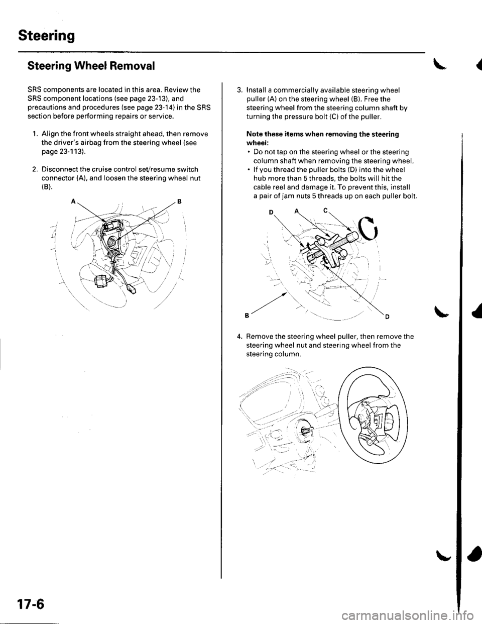
1. Align the front wheels straight ahead, then remove
the driver's airbag from the steering wheel (see
page 23-113).
2. Disconnect the cruise control sevresume switch
connector (A), and loosen the steering wheel nut
{B).
i
17-6
3. Install a commercially available steering wheel
puller {A) on the steering wheel (B). Free the
steering wheel from the steering column shaft by
turning the pressure bolt (C) ofthe puller.
Note these items when removing the steering
wheel:. Do not tap on the steering wheel orthesteering
column shaft when removing the steering wheel.. lf you thread the puller bolts (D) intothewheel
hub more than 5 threads, the bolts will hit the
cable reel and damage it. To prevent this, install
a pair of jam nuts 5 threads up on each puller bolt.
D
Bemove the steering wheel puller, then remove the
steering wheel nut and steering wheel from the
sleerino column.
{