Dashboard removal HONDA CIVIC 2003 7.G Workshop Manual
[x] Cancel search | Manufacturer: HONDA, Model Year: 2003, Model line: CIVIC, Model: HONDA CIVIC 2003 7.GPages: 1139, PDF Size: 28.19 MB
Page 211 of 1139
Fuel and Emissions Systems
General Troubleshooting Information (cont'dl
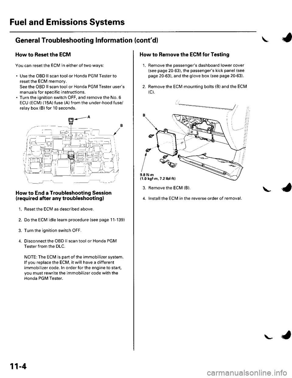
How to Reset the ECM
You can reset the ECM in either of two ways:
. Use the OBD ll scantool or Honda PGMTesterto
reset the ECM memory.
See the OBD ll scan tool or Honda PGI\4 Tester user's
manuals for specific instructions.' Turn the ignition switch OFF, and remove the No. 6
ECU {ECM} (15A) fuse (A)from the under-hood fuse/
relav box (Blfor 10 seconds.
How to End a Troubleshooting Session
(required after any troubleshootingl
1. Reset the ECM as described above.
2. Do the ECM idle learn procedure (see page 11-139)
3. Turn the ignition switch OFF.
4. Disconnectthe OBD ll scan tool or Honda PGM
Tester from the DLC.
NOTE: The ECM is part of the immobilizer system.
lf vou replace the ECM, it will have a different
immobilizer code. In order for the engine to start,
you must rewrite the immobilizer code with the
Honda PGM Tester.
11-4
\- ta
J
How to Remove the ECM for Testing
1. Remove the passenger's dashboard lower cover
{see page 20-63), the passenger's kick panel (see
page 20-63), and the glove box (see page 20-63).
2. Remove the ECM mounting bolts (B) and the ECM
(c),
9.8 N.m{1.0 kgf.m,7.2lbt.ft}
3. Remove the ECM (B).
4. Installthe ECM in the reverse order of removal.
L
Page 501 of 1139
T
\
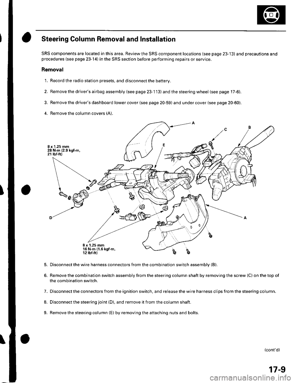
Steering Column Removal and Installation
SRS components are located in this area. Review the SRS component locations (see page 23-13) and precautions andprocedures (see page 23-14) in the SRS section before performing repairs or service.
Removal
1, Record the radio station presets, and disconnect the battery.
2. Removethedriver'sairbagassembly(seepage23-113) and the steering wheel (see page 17-6).
3. Removethe driver's dashboard lowercover(see page 20-59) and undercover(see page 20-60).
4. Remove the column covers (A:
I x 1.25 mm16 N.m (1.6 kgf.m,12 lbl.fr)b
5.
6.
Disconnect the wire harness connectors from the combination switch assembly {B).
Remove the combination switch assembly from the steering column shaft by removing the screw (C) on the top of
the combination switch.
7. Disconnect the connectors from the ignition switch, and release the wire harness clips from the steering column.
8. Disconnect the steering joint (D), and remove it from the column shaft.
9. Remove the steering column {E) by removingthe attaching nuts and bolts.
(cont'd)
17-9
Page 542 of 1139
Steering Gearbox Removal
Special Tool Required
Ball ioint remover,2S mm 0TlvlAC-S100200
1. Raise the front of vehicle, and make sure it is
securely supponed.
2. Remove the front wheels.
Remove the driver's airbag (seepage23-113).
Remove the steering wheel (see page 17-6).
Remove the motor on the steering gearbox (see
page l T-49).
Remove the driver's dashboard lower cover (see
page 20-59) and under cover {see page20-60).
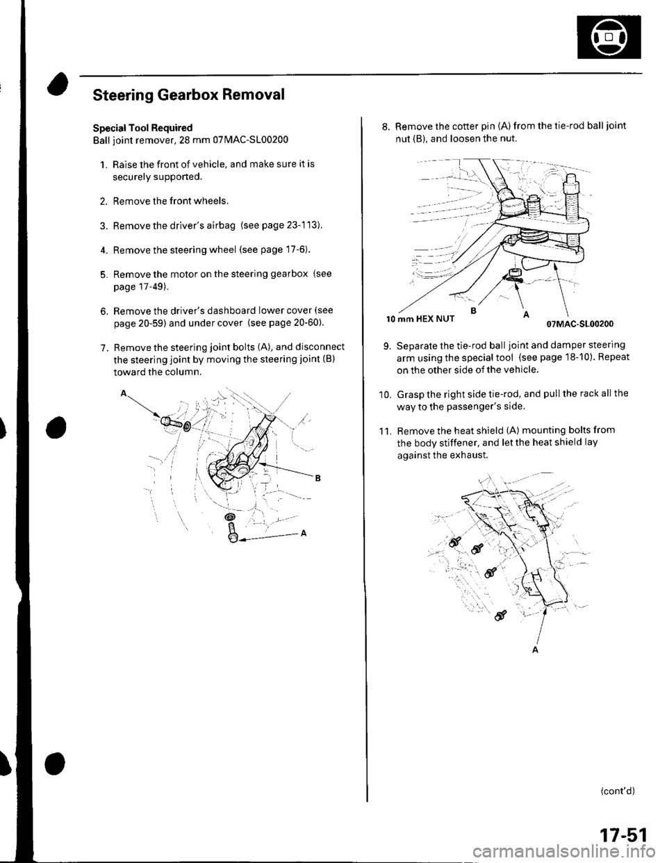
Remove the steering joint bolts (A), and disconnect
the steering joint by moving the steering joint (B)
toward the column.
4.
5.
6.
7.
'il
_t\
l- '/
,a.: --L -
8. Remove the cotter pin (A)from the tie-rod balljoint
nut {B), and loosen the nut.
r0 mm HEX NUT07MAC-S100200
Separate the tie-rod balljoint and damper steering
arm using the special tool (see page 18-10). Repeat
on the other side of the vehicle.
Grasp the right side tie-rod, and pull the rack all the
way to the passenger's side,
Remove the heat shield (A) mounting bolts from
the body stiffener, and let the heat shield lay
against the exhaust.
11.
9.
10.
(cont'd)
17-51
Page 654 of 1139
Body
DoorsComponent Location Index ...........Door Panel Removal/lnstallation .....,..........Door Outer Handle ReplacementDoor Latch ReplacementDoor Glass and RegulatorReplacementDoor Sash Trim Replacement .......................
Door Glass Outer WeatherstripReplacement
Door Weatherstrip Beplacement
Door Glass Adjustment .................................Door Position Adjustment .............................Door Striker Adiustment ................................MirrorsComponent Location Index ...........................Power Mirror Replacement ...........................Mirror Holder Replacement ...........................Rearview Mirror Rep1acement ......................
GlassComponent Location Index ...........................Windshield Replacement
Bear Window Rep1acement ...........................
Ouarter Glass Replacement ..........................MoonroofComponent Location Index ...........................Symptom Troubleshooting Index
Glass Height Adjustment ...............................
Glass ReplacementWind Def lector 8ep1acement ........................Drain Channel Rep1acement ..........................Sunshade Replacement .................................Motor ReplacementFrame and Drain Tube Replacement ............Drain Channel Slider and Cable AssemblyReplacementLimit Switch Adjustment ...............................Closino Force and ODenina Draq Check ......lnterioi TrimComponent Location Index ...........................Trim Removal/lnstallation DoorArea ..........Trim Removal/lnstallation-Rear Side AreaTrim Removal/lnstallation-Cargo Floor AreaTrim Removal/lnstallation-Hatch Area .........Headliner Removal/lnstallation* Carpet Rep1acement .......................................ConsolesConsoles, Front and RearRemova l/lnsta llationFront Console Disassembly/Reassembly .....
20-220,420-620-7
20-920 t0
20- 10
20-1120-1120-1220 13
20-1420-1520-1520-16
20 1120-1920-2520-29
20,3520-3620-3720-3120-3820 3920-4020-4120,42
20 4420-4620,44
20-4920 50
20-51
DashboardInstrument Panel Removal/lnstallation ........Driver's Dashboard Lower CoverRemovat InstallationDriver's Dashboard Under CoverRemova t Insta llation
Oriver's Pocket Removal/lnstallation ............Shift Lever Trim Removal/lnstallation ..........Center Panel Removal/lnstallation ...............Passenger's Dashboard Lower CoverRemova l/lnsta llat ionx Glove Box Removal/lnstallationDashboard Side VentRemoval/lnstallation .................................. 20-64Beverage Holder Removal/lnstallation ........ 20-64Driver'sTray Removal/lnstallation ............... 20-65Passenger's Tray Removal/lnstallation ........ 20 65* Dashboard Removal/lnstallation .................. 20-66Steerinq Hanqer Beam Reolacement ........... 20-68Seats "
Component Location Index ........................... 20-10* Front Seat Removal/lnstallation ................... 20-11* Front Seat Disassembly/Reassembly-Driver's .................................. 20-73* Front Seat Disassembly/Reassembly-Passenger's ........................... 20-74* Front Seat Cover Replacement ..................... 2O-75Rear Seat Removal/1nsta11ation ..................... 20-80Rear Seat-back Latch Replacement .............. 20-81Rear Seat-backStriker Replacement ............ 20-81
20-59
20-59
Rear Seat-back Cover Replacement ............. 20-82Rear Seat Cushion Cover Replacement ....... 20.84BumpersFront Bumper Removal/lnstallation .............Rear Bumoer Removal/lnstallation ...............HoodAdjustmentHood Seal ReplacementHood Insulator Rep1acement .........................Hatch
20-6020,6020 6120-62
20-63
20-63
20,8520-86
20-4720,8820,89
20-5220-5320-5420-55
20-5720-58
Adjustment ................... 20-90Hatch Suppon Strut Replacement ................ 20-91Hatch WeatherstriD Reo1acement ................. 20-92
Fuel Fill DoorAdiustment ................... 20-93Exterior TrimFront Grille Replacement ..............Cowl Covers Replac"rn""t .. . .....................A pillar Corner Trim Replacement ................Roof lMolding Replacement ...........................Rear License Trim ReplacementHatch Spoiler 8ep1acement ...........................Emblem Rep1acement .........................
20-9420-9520-9620-9720,9820-9920-100
Page 709 of 1139
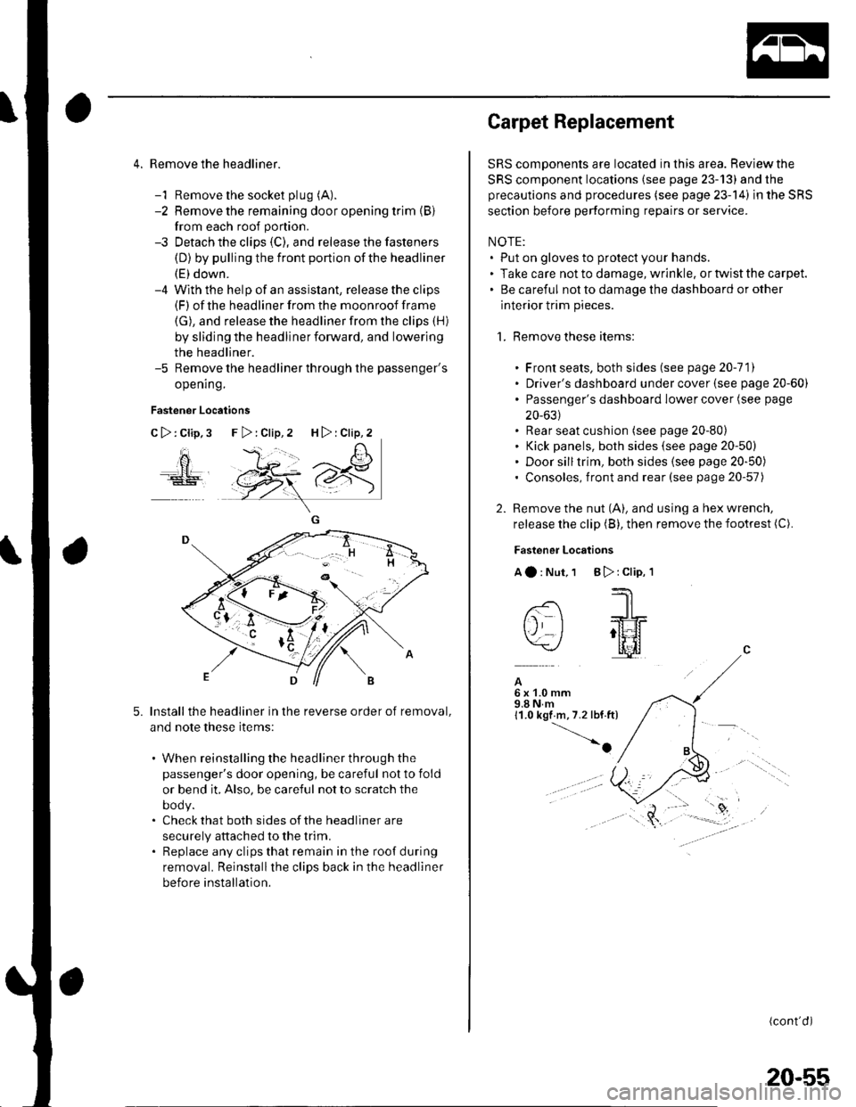
4. Remove the headliner.
-1 Remove the socket plug (A).
-2 Remove the remaining door opening trim {B}
from each roof portion.
-3 Detach the clips (C), and release the fasteners
(D) by pulling the front portion ofthe headliner
(E) down.-4 With the help of an assislant, release the clips(F) of the headliner from the moonroof frame
(G), and release the headliner from the clips (H)
by sliding the headliner forward, and lowering
the headliner.-5 Remove the headliner through the passenger's
opening.
Fastener Locations
C>:Clip,3
ao
5.Install the headliner in the reverse order of removal,
and note these items:
. When reinstalling the headliner through the
passenger's door opening, be careful not to fold
or bend it, Also, be careful not to scratch the
DOOy.. Check that both sides of the headliner are
securely attached to the trim.. Replace any clips that remain in the roof during
removal. Reinstallthe clips back in the headliner
before installation.
F>:Clip,2 H>:Clip,2
Carpet Replacement
SRS components are located in this area. Reviewthe
SRS component locations (see page 23-13) and the
precautions and procedures (see page 23-14) in the SRS
section before performing repairs or service.
NOTE:. Put on gloves to protect your hands.. Take care not to damage, wrinkle. or twist the carpet.. Be careful not to damage the dashboard or other
interior trim pieces.
1. Remove these items:
. Front seats, both sides (see page 20-111. Driver's dashboard under cover (see page 20-60). Passenger's dashboard Iower cover (see page
20-631. Rear seat cushion (see page 20-80). Kick panels, both sides (see page 20-50). Door silltrim, both sides (see page 20-50). Consoles, front and rear (see page 20-57)
2. Remove the nut (A), and using a hex wrench,
release the clip (B), then remove the footrest (C).
Fastener Locations
Aa:Nut,1 B):Clip,'l
--'1 I
-- -JrL
tj I ;tt4f=\-/ l[il
A6x1.0mm9.8Nm11.0 kgf m,7.2 lbf.ft)
-o
(cont'd)
20-55
Page 711 of 1139
Consoles
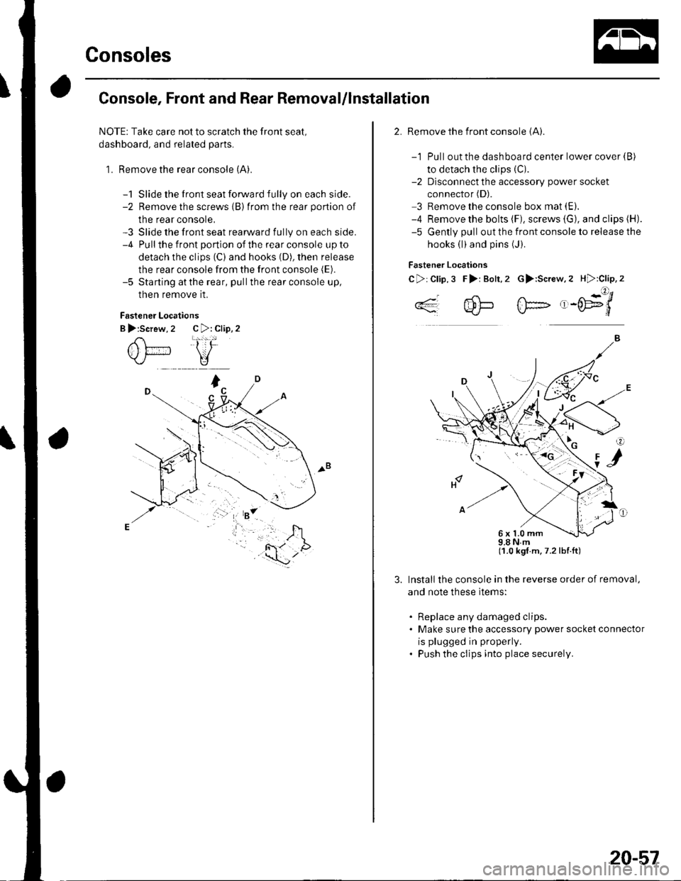
Console, Front and Rear Removal/lnstallation
NOTE: Take care not to scratch the front seal,
dashboard, and related parts.
1. Remove the rear console (A).
-1 Slide the front seat forward fully on each side.-2 Remove the screws {B)from the rear portion of
the rear console,-3 Slide the front seat rearward fully on each side.-4 Pullthe front portion of the rear console up to
detach the clips (C) and hooks (D), then release
the rear console from the front console (E).
-5 Starting atthe rear, pullthe rear console up,
then remove it.
Fastener Locations
B >:Screw, 2 C >: Clip, 2
2. Remove the front console (A).
-1 Pull out the dashboard center lower cover {B)
to detach the clips (C).
-2 Dlsconnect the accessory power socket
connector (D).
3 Remove the console box mat (E).
-4 Remove the bolts (F), screws (G), and clips (H).
-5 Gently pull out the front console to release the
hooks (l)and pins (J).
Fastener Locations
C>:Clip,3 F>i Bolt,2 G>:Screw.2 H):Clip,2
..4- 4!-- fF- ,-('E9'/*'*q'J-L}*J\./-d
98Nm(1.0 kgt.m,7.2lbf.ft)
Install the console in the reverse order of removal,
and note these ltems:
. Replace any damaged clips.. Make sure the accessory power socket connector
is plugged in properly.
. Push the clips into place securely.
6x1.0mm
20-57
Page 713 of 1139
Dashboard
Instrument Panel Removal/
Installation
NOTE:. When prying with a flat-tip screwdriver, wrap it withprotective tape, and apply protective tape around the
related parts, to prevent damage.. Take care not to scratch the dashboard and related
pa rts.
1. Tilt the steering column down.
2. Remove the steering column upper cover {see page
17,9).
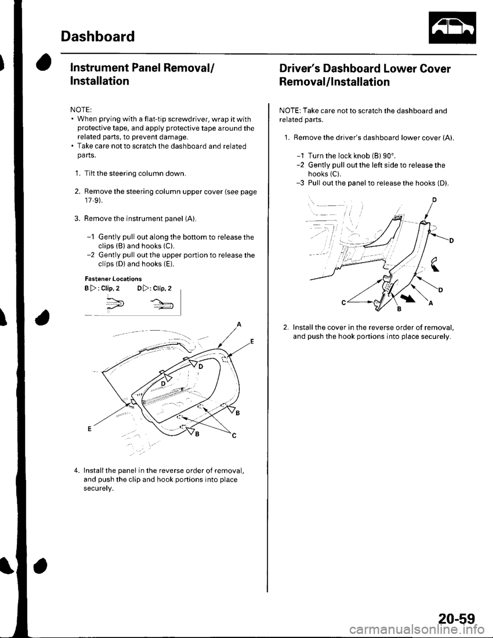
Remove the instrument panel (A).
-1 Gently pull out along the bottom to release the
clips (B) and hooks (C).
-2 Gently pull out the upper portion to release the
clips (D) and hooks (E).
Fastener Locations
B >: clip.2 DD,: Clip,2
^*,
4.Installthe panel in the reverse order of removal,
and push the clip and hook portions into place
securery.
Driver's Dashboard Lower Cover
Removal/lnstallation
NOTE: Take care not to scratch the dashboard and
related Parts.
1. Remove the driver's dashboard lower cover (A).
-1 Turn the lock knob (B) 90".-2 Gently pull out the left side to release the
hooks (C),
-3 Pull out the panelto release the hooks (D).
Installthe cover in the reverse order of removal,
and push the hook portions into place securely.
20-59
Page 714 of 1139
Dashboard
Driver's Dashboard Under Cover
Removal/lnstallation
NOTE: Take care not to scratch the dashboard and
related parts.
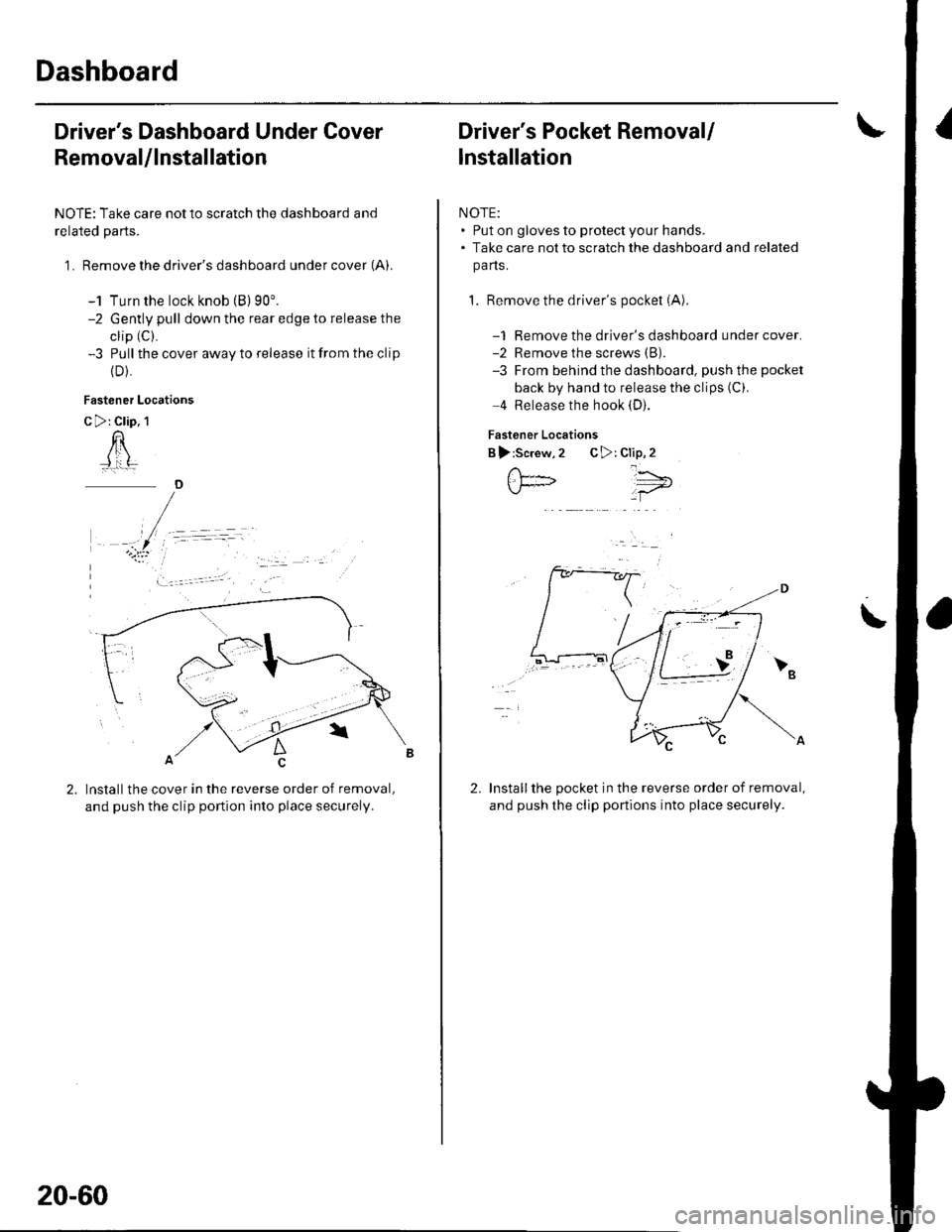
1 . Remove the driver's dashboard under cover (A).
-1 Turn the lock knob (B) 90'.-2 Gently pull down the rear edge to release the
clip (C).
-3 Pull the cover away to release it from the clip
{D).
Fastener Locations
C >: Clip. 1
n
Installthe cover in the reverse order of removal,
and push the clip portion into place securely.
)
20-60
Driver's Pocket Removal/
lnstallation
NOTE:. Put on gloves to protect your hands.. Take care not to scratch the dashboard and related
pa ns.
1. Remove the driver's pocket (A)
-1 Remove the driver's dashboard under cover.-2 Remove the screws (B).
-3 From behind the dashboard, push the pocket
back by hand to release the clips (C).
4 Release the hook (D).
Fastener Locations
B ):Screw,2 C>: Clip,2
Installthe pocket in the reverse order of removal,
and push the clip portions into place securely.
','"\5;;t='
\
2.
Page 715 of 1139
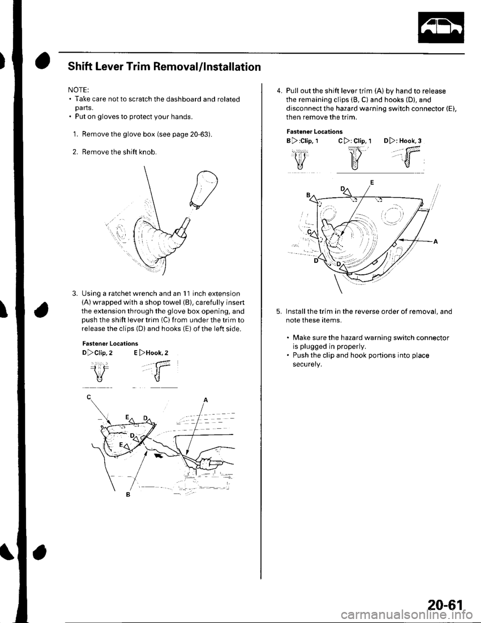
Shift Lever Trim Removal/lnstallation
NOTE:. Take care not to scratch the dashboard and related
pa rts.. Put on gloves to protect your hands.
1. Remove the glove box (see page 20-63).
2. Remove the shift knob.
Using a ratchet wrench and an 11 inch extension(A) wrapped with a shop towel (B), carefully insert
the extension through the glove box opening, andpush the shift lever trim (C) from under the trim to
release the clips (D) and hooks (E) of the left side.
Fastener
D>clip,
i:F\V
Locations
2 E >Hook,2
.-a7
-t1
u
4. Pull outthe shift levertrim (A) by hand to release
the remaining cllps (8, C) and hooks (D), and
disconnect the hazard warning switch connector (El,
then remove the trim.
Fastener Locations
B >:Clip, 1C>: Cl;p, 1 D>: Hook,3
,,.;w,
Install the trim in the reverse order of removal, and
note these rtems.
. Make sure the hazard warning switch connectot
is plugged in properly.. Push the clip and hook portions into place
securely,
-
,,
20-61
Page 716 of 1139
Dashboard
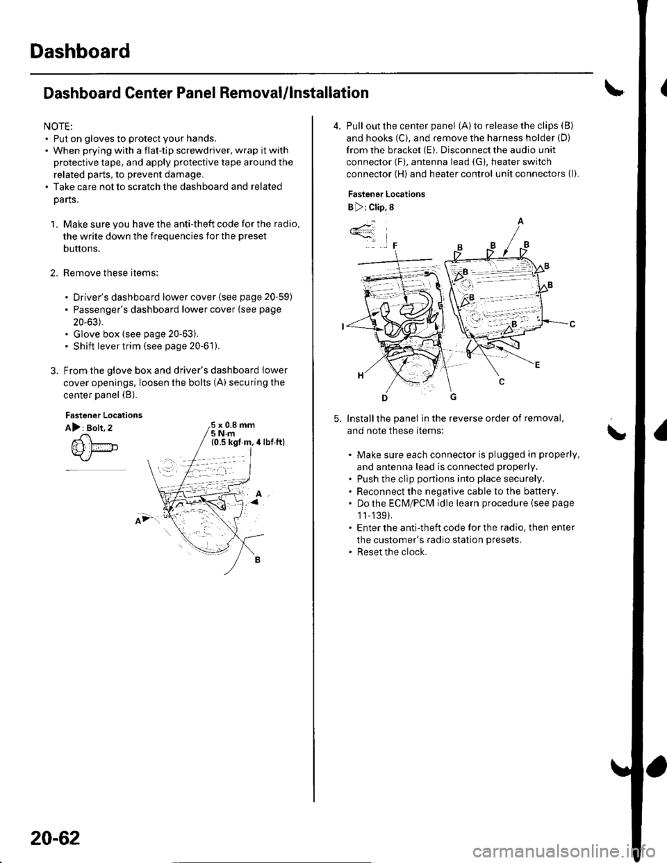
Dashboard Center Panel Removal/lnstallation
NOTE:. Put on gloves to protect your hands.. When prying with a flat-tip screwdriver, wrap it with
protective tape, and apply protective tape around the
related parts, to prevent damage.. Take care not to scratch the dashboard and related
parts.
1. Make sure you have the anti-theft code for the radio,
the write down the frequencies for the preset
buttons.
Remove these items:
. Driver's dashboard lower cover (see page 20-59)
. Passenger's dashboard lower cover (see page
20-63).. Glove box (see page 20-63).. Shift lever trim {see page 20-61).
From the glove box and driver's dashboard Iower
cover openings, loosen the bolts (A) securing the
center panel (B).
2.
Fastener Locations
A): Bolt, 2x 0.8 mm5Nm
;.'
20-62
4. Pull out the center panel (A) to release the clips (B)
and hooks (C), and remove the harness holder (D)
from the bracket (E). Disconnect the audio unit
connector (F), antenna lead (G), heater switch
connector (H) and heater control unit connectors (l).
Fastener Locations
B ): Clip, 8
Installthe panel in the reverse order of removal,
and note these items:
Make sure each connector is plugged in properly,
and antenna lead is connected properly.
Push the clip portions into place securely.
Reconnect the negative cable to the battery.
Do the ECN4/PCt\4 idle learn procedure {see page
1l-139).
Enter the anti-theft code for the radio. then enter
the customer's radio station presets.
Reset the clock.
*4
,F
\