Remove dashboard HONDA CIVIC 2003 7.G Workshop Manual
[x] Cancel search | Manufacturer: HONDA, Model Year: 2003, Model line: CIVIC, Model: HONDA CIVIC 2003 7.GPages: 1139, PDF Size: 28.19 MB
Page 77 of 1139
Cruise Control
1.
Main Switch Test/Replacement
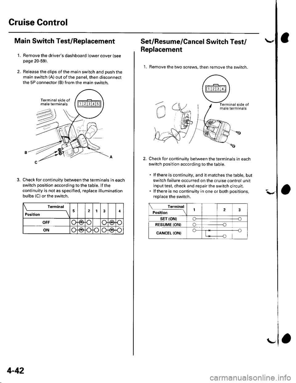
Remove the driver's dashboard lower cover (see
page 20-59).
Release the clips of the main switch and push the
main switch 1A) out of the panel, then disconnect
the 5P connector (B) from the main switch.
Check for continuity between the terminals in each
switch position according to the table. lf the
continuity is not as specified, replace illumination
bulbs (C) or the switch.
\-------11v1
Position14
OFF(9@
ONo@o\Jo
4-42
r\--
Set/Resume/Cancel Switch Test/
Replacement
1. Remove the two screws. then remove the switch.
Check for continuity between the terminals in each
switch position according to the table.
. lfthere is continuity, and it matches the table, but
switch failure occurred on the cruise control unit
input test, check and repair the switch circult.. lf there is no continuity in one or both positions,
replace the switch.
Terminal
;"itl* '\2
sET (ONtCF--o
RESUME ION)o--o
CANCEL {ON}o
Page 211 of 1139
Fuel and Emissions Systems
General Troubleshooting Information (cont'dl
How to Reset the ECM
You can reset the ECM in either of two ways:
. Use the OBD ll scantool or Honda PGMTesterto
reset the ECM memory.
See the OBD ll scan tool or Honda PGI\4 Tester user's
manuals for specific instructions.' Turn the ignition switch OFF, and remove the No. 6
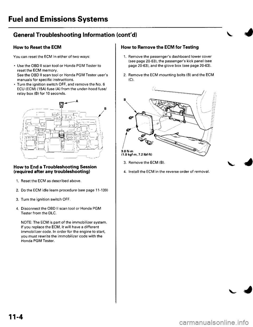
ECU {ECM} (15A) fuse (A)from the under-hood fuse/
relav box (Blfor 10 seconds.
How to End a Troubleshooting Session
(required after any troubleshootingl
1. Reset the ECM as described above.
2. Do the ECM idle learn procedure (see page 11-139)
3. Turn the ignition switch OFF.
4. Disconnectthe OBD ll scan tool or Honda PGM
Tester from the DLC.
NOTE: The ECM is part of the immobilizer system.
lf vou replace the ECM, it will have a different
immobilizer code. In order for the engine to start,
you must rewrite the immobilizer code with the
Honda PGM Tester.
11-4
\- ta
J
How to Remove the ECM for Testing
1. Remove the passenger's dashboard lower cover
{see page 20-63), the passenger's kick panel (see
page 20-63), and the glove box (see page 20-63).
2. Remove the ECM mounting bolts (B) and the ECM
(c),
9.8 N.m{1.0 kgf.m,7.2lbt.ft}
3. Remove the ECM (B).
4. Installthe ECM in the reverse order of removal.
L
Page 213 of 1139
Fuel and Emissions Systems
General Troubleshooting Information (cont'd)
ECM Updating and Substitution for Testing
Special Tools Bequired
Honda Interface Module (HlM) EOS05435570
Use this procedure when you have to substitute a
known-good ECM in a troubleshooting procedure.
U pdate the ECM only if the ECN4 does not already have
the latest software loaded,
NOTE;. lMake sure the battery is fully charged before you
update the ECN4.. To prevent ECM damage during the update, do not
turn the ignition switch OFF, and do not use any of
the vehicle's electrical devices (light, horn, radio, etc. ).
How to Update the ECM
1. Turn the ignition switch ON (ll). Do not startthe
eng Ine.
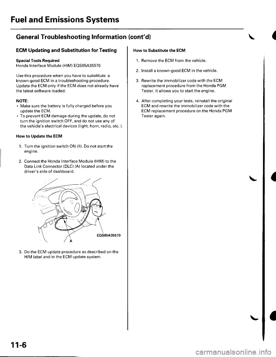
2. Connect the Honda lnterface Module (HlM) to the
Data Link Connector {DLC) (A) located under the
driver's side of dashboard.
EOS05A35570
Do the ECM update procedure as described on the
HlN4 label and in the ECM update system.
11-6
\-
How to Substitute the ECM
'1. Remove the ECM f rom the vehicle.
2. Install a known-good ECM in the vehicle.
3. Rewrite the immobilizer code with the ECM
replacement procedure from the Honda PGM
Tester. lt allows you to start the engine.
4. After completing your tests, reinstall the original
ECM and rewrite the immobilizer code with the
ECM replacement procedure on the Honda PGM
Tester again.
L
(
I
Page 501 of 1139
T
\
Steering Column Removal and Installation
SRS components are located in this area. Review the SRS component locations (see page 23-13) and precautions andprocedures (see page 23-14) in the SRS section before performing repairs or service.
Removal
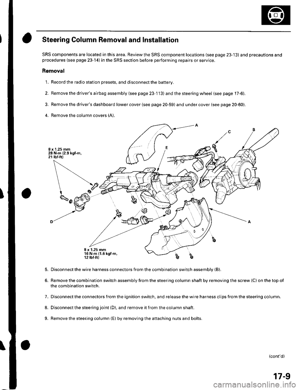
1, Record the radio station presets, and disconnect the battery.
2. Removethedriver'sairbagassembly(seepage23-113) and the steering wheel (see page 17-6).
3. Removethe driver's dashboard lowercover(see page 20-59) and undercover(see page 20-60).
4. Remove the column covers (A:
I x 1.25 mm16 N.m (1.6 kgf.m,12 lbl.fr)b
5.
6.
Disconnect the wire harness connectors from the combination switch assembly {B).
Remove the combination switch assembly from the steering column shaft by removing the screw (C) on the top of
the combination switch.
7. Disconnect the connectors from the ignition switch, and release the wire harness clips from the steering column.
8. Disconnect the steering joint (D), and remove it from the column shaft.
9. Remove the steering column {E) by removingthe attaching nuts and bolts.
(cont'd)
17-9
Page 542 of 1139
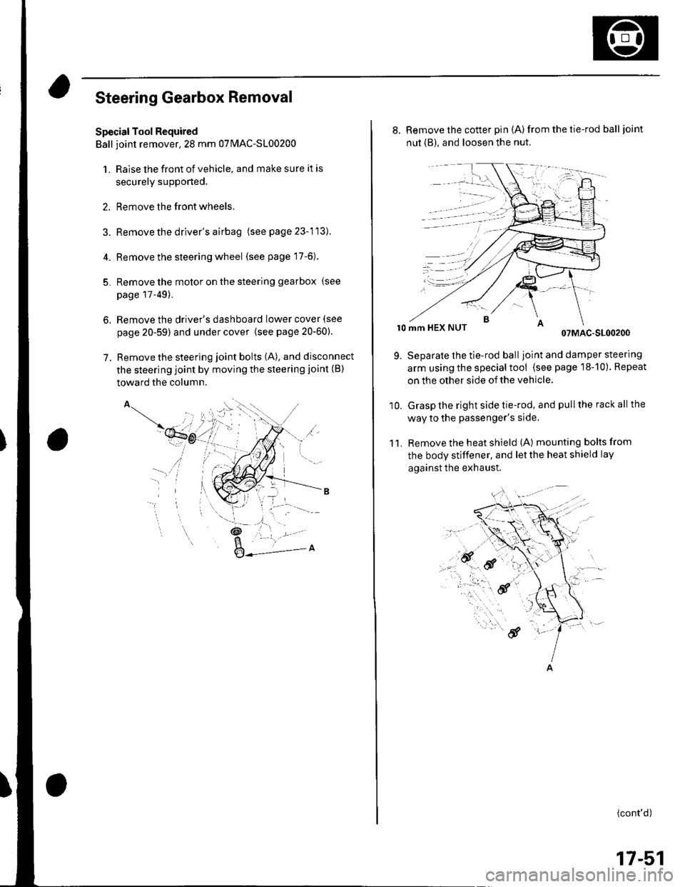
Steering Gearbox Removal
Special Tool Required
Ball ioint remover,2S mm 0TlvlAC-S100200
1. Raise the front of vehicle, and make sure it is
securely supponed.
2. Remove the front wheels.
Remove the driver's airbag (seepage23-113).
Remove the steering wheel (see page 17-6).
Remove the motor on the steering gearbox (see
page l T-49).
Remove the driver's dashboard lower cover (see
page 20-59) and under cover {see page20-60).
Remove the steering joint bolts (A), and disconnect
the steering joint by moving the steering joint (B)
toward the column.
4.
5.
6.
7.
'il
_t\
l- '/
,a.: --L -
8. Remove the cotter pin (A)from the tie-rod balljoint
nut {B), and loosen the nut.
r0 mm HEX NUT07MAC-S100200
Separate the tie-rod balljoint and damper steering
arm using the special tool (see page 18-10). Repeat
on the other side of the vehicle.
Grasp the right side tie-rod, and pull the rack all the
way to the passenger's side,
Remove the heat shield (A) mounting bolts from
the body stiffener, and let the heat shield lay
against the exhaust.
11.
9.
10.
(cont'd)
17-51
Page 673 of 1139
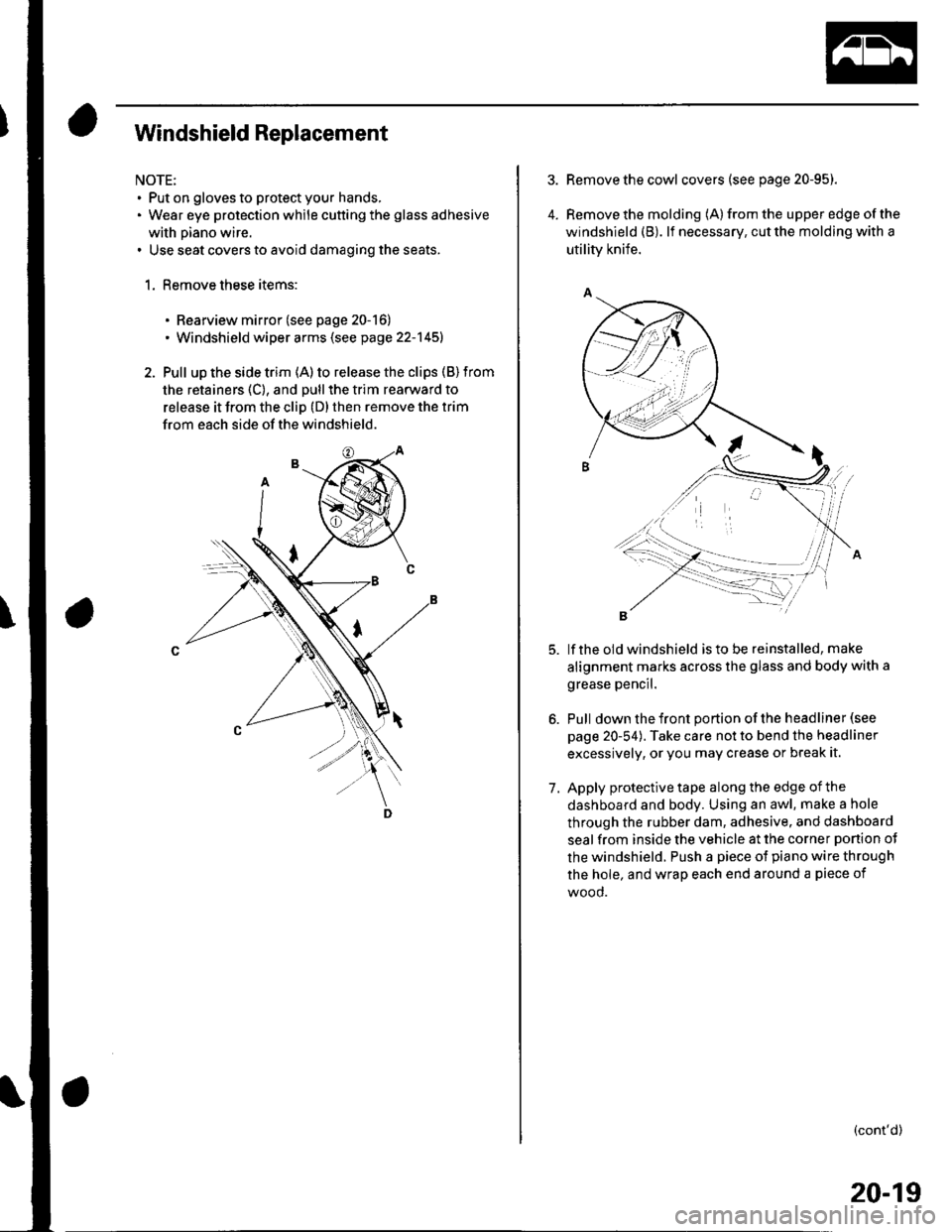
Windshield Replacement
NOTE:. Put on gloves to protect your hands,. Wear eye protection while cutting the glass adhesive
with piano wire.. Use seat covers to avoid damaging the seats.
1. Remove these items:
. Rearview mirror (see page 20-16). Windshield wiper arms (see page 22-145)
2. Pull up the side trim (A) to release the clips (B) from
the retainers (C), and pull the trim rearward to
release it from the cliD (D) then remove the trim
from each side of the windshield.
4.
Remove the cowl covers (see page 20-95).
Remove the molding (A) from the upper edge of the
windshield (B). lf necessary, cut the molding with a
utility knife.
lf the old windshield is to be reinstalled, make
alignment marks across the glass and body with a
grease pencil.
Pull down the front portion of the headliner (see
page 20-54). Take care not to bend the headliner
excessively, or you may crease or break it.
Apply protective tape along the edge of the
dashboard and body. Using an awl, make a hole
through the rubber dam, adhesive. and dashboard
seal from inside the vehicle at the corner ponion ot
the windshield. Push a piece of piano wire through
the hole, and wrap each end around a piece of
wood.
(cont'd)
7.
20-19
Page 674 of 1139
Glass
Windshield Replacement (cont'd)
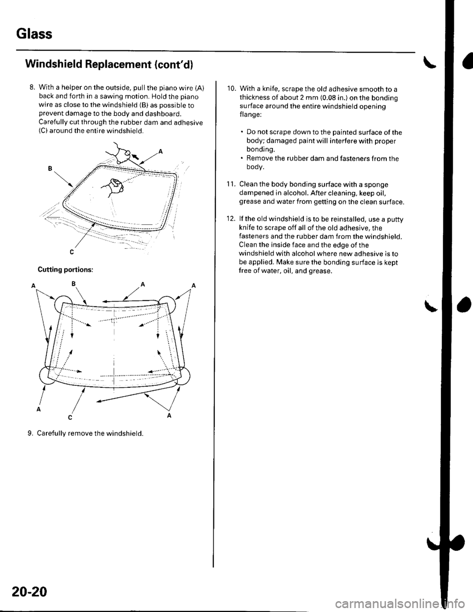
With a helper on the outside, pullthe piano wire {A)back and forth in a sawing motion. Hold the piano
wire as close to the windshield (B) as possible toprevent damage to the body and dashboard.
Carefully cut through the rubber dam and adhesive(C) around the entire windshield.
-A\, ,.-
,,t""""""""',-\i-.. -1:-, -
-=�-.--
20-20
10. With a knife, scrape the old adhesive smooth to a
thickness of about 2 mm (0.08 in.) on the bonding
surface around the entire windshield opening
flange:
. Do not scrape down to the painted surface ofthe
body; damaged paint will interfere with proper
bonding.. Remove the rubber dam and fasteners from the
oooy.
1 1. Clean the body bonding surface with a sponge
dampened in alcohol. After cleaning, keep oil,grease and water from getting on the clean surface.
12. lf the old windshield is to be reinstalled, use a puttv
knife to scrape off all of the old adhesive, the
fasteners and the rubber dam from the windshield.
Clean the inside face and the edge of the
windshield with alcohol where new adhesive is to
be applied. Make sure the bonding surface is kept
free of water, oil, and grease.
\
Page 708 of 1139
Interior Trim
Headliner RemovaUlnstallation
NOTE:. When prying with a flat-tip screwdriver, wrap itwith
protective tape to prevent damage.. Take care not to bend and scratch the headliner.. Be careful not to damage the dashboard and other
interior trim.
1. Remove these items:
. A-pillar trim, both sides (see page 20-50). B-pillar uppertrim, both sides (see page 20-50). Hatch weatherstrip, as necessary {see page 20-
92\. C-pillar trim, both sides (see page 20-51). Moonroof switch (see page 22-'112). Spotlights (see page 22-961. Ceiling light (see page 22-96)
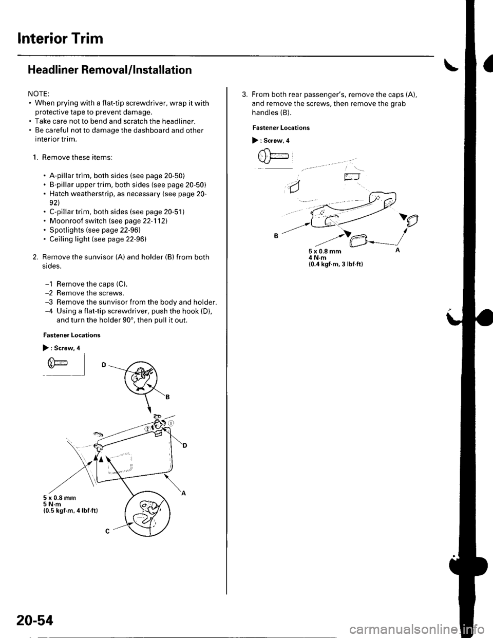
Remove the sunvisor {A) and holder {B) from both
srdes.
-1 Remove the caps {C).-2 Remove the screws.-3 Remove the sunvisor from the body and holder.-4 Using a flat-tip screwdriver, push the hook (D),
and turn the holder 90'. then pull it out.
Fastener Locations
> : Screw, 4
r(\'-r)*
5x0.8mm5 N.m{0.5 kst m.4lbf ft}
20-54
3. From both rear passenger's, remove the caps (A),
and remove the screws, then remove the grab
handles (B).
Fastener Locations
> : Screw, 4
t , t;---iJ
)e
5x0.8mm4 N.m{0.4 kgf.m, 3 lbf.ft}
Page 709 of 1139
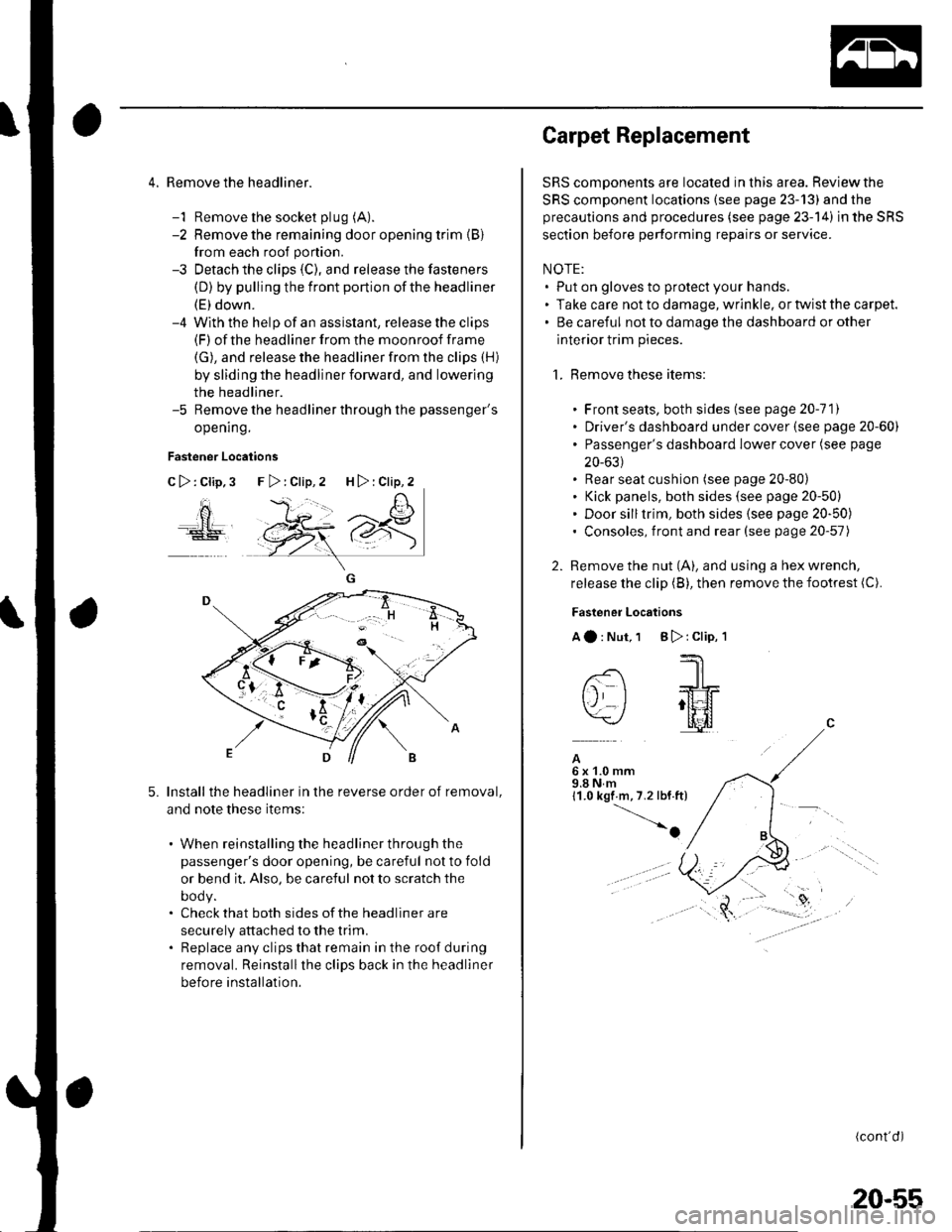
4. Remove the headliner.
-1 Remove the socket plug (A).
-2 Remove the remaining door opening trim {B}
from each roof portion.
-3 Detach the clips (C), and release the fasteners
(D) by pulling the front portion ofthe headliner
(E) down.-4 With the help of an assislant, release the clips(F) of the headliner from the moonroof frame
(G), and release the headliner from the clips (H)
by sliding the headliner forward, and lowering
the headliner.-5 Remove the headliner through the passenger's
opening.
Fastener Locations
C>:Clip,3
ao
5.Install the headliner in the reverse order of removal,
and note these items:
. When reinstalling the headliner through the
passenger's door opening, be careful not to fold
or bend it, Also, be careful not to scratch the
DOOy.. Check that both sides of the headliner are
securely attached to the trim.. Replace any clips that remain in the roof during
removal. Reinstallthe clips back in the headliner
before installation.
F>:Clip,2 H>:Clip,2
Carpet Replacement
SRS components are located in this area. Reviewthe
SRS component locations (see page 23-13) and the
precautions and procedures (see page 23-14) in the SRS
section before performing repairs or service.
NOTE:. Put on gloves to protect your hands.. Take care not to damage, wrinkle. or twist the carpet.. Be careful not to damage the dashboard or other
interior trim pieces.
1. Remove these items:
. Front seats, both sides (see page 20-111. Driver's dashboard under cover (see page 20-60). Passenger's dashboard Iower cover (see page
20-631. Rear seat cushion (see page 20-80). Kick panels, both sides (see page 20-50). Door silltrim, both sides (see page 20-50). Consoles, front and rear (see page 20-57)
2. Remove the nut (A), and using a hex wrench,
release the clip (B), then remove the footrest (C).
Fastener Locations
Aa:Nut,1 B):Clip,'l
--'1 I
-- -JrL
tj I ;tt4f=\-/ l[il
A6x1.0mm9.8Nm11.0 kgf m,7.2 lbf.ft)
-o
(cont'd)
20-55
Page 711 of 1139
Consoles
Console, Front and Rear Removal/lnstallation
NOTE: Take care not to scratch the front seal,
dashboard, and related parts.
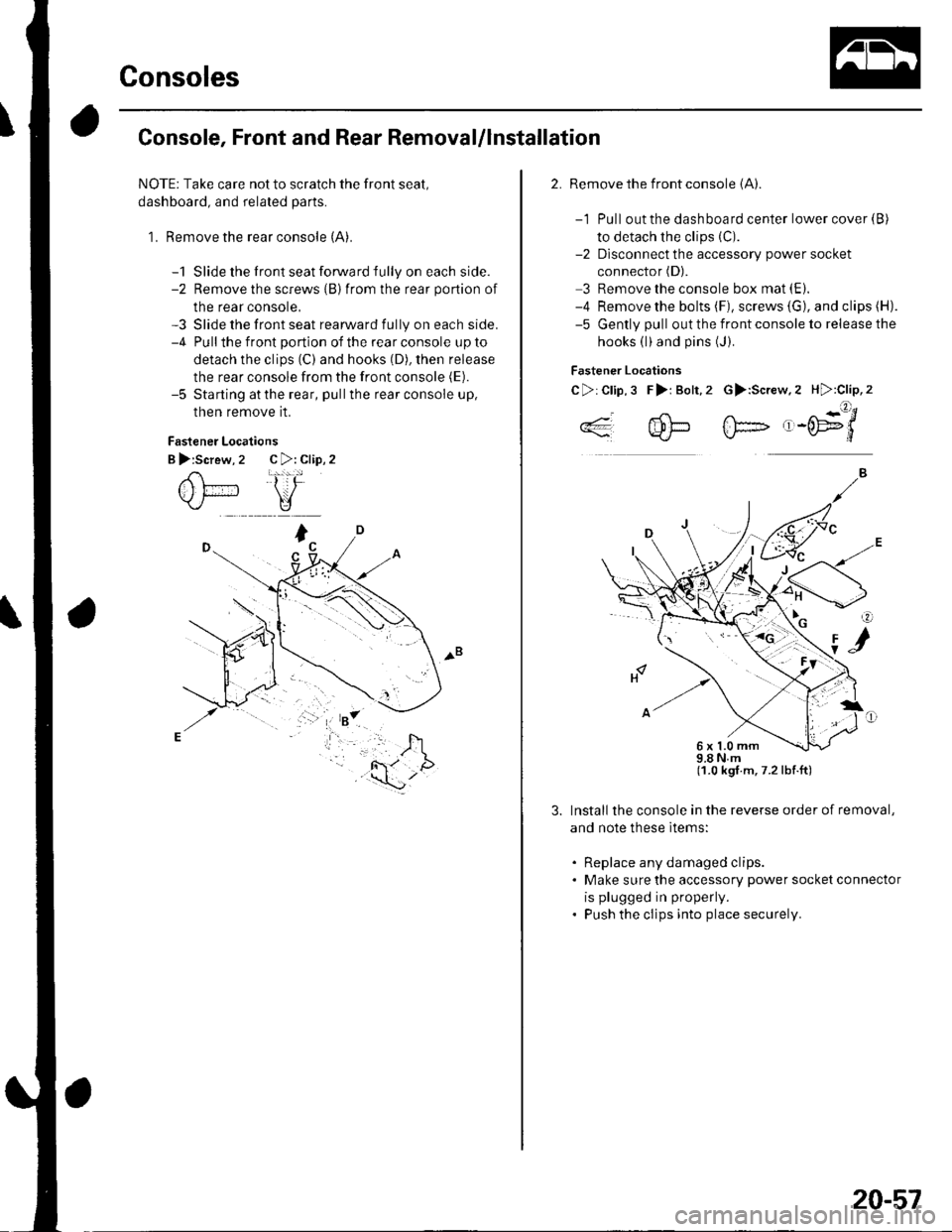
1. Remove the rear console (A).
-1 Slide the front seat forward fully on each side.-2 Remove the screws {B)from the rear portion of
the rear console,-3 Slide the front seat rearward fully on each side.-4 Pullthe front portion of the rear console up to
detach the clips (C) and hooks (D), then release
the rear console from the front console (E).
-5 Starting atthe rear, pullthe rear console up,
then remove it.
Fastener Locations
B >:Screw, 2 C >: Clip, 2
2. Remove the front console (A).
-1 Pull out the dashboard center lower cover {B)
to detach the clips (C).
-2 Dlsconnect the accessory power socket
connector (D).
3 Remove the console box mat (E).
-4 Remove the bolts (F), screws (G), and clips (H).
-5 Gently pull out the front console to release the
hooks (l)and pins (J).
Fastener Locations
C>:Clip,3 F>i Bolt,2 G>:Screw.2 H):Clip,2
..4- 4!-- fF- ,-('E9'/*'*q'J-L}*J\./-d
98Nm(1.0 kgt.m,7.2lbf.ft)
Install the console in the reverse order of removal,
and note these ltems:
. Replace any damaged clips.. Make sure the accessory power socket connector
is plugged in properly.
. Push the clips into place securely.
6x1.0mm
20-57