code HONDA CIVIC 2003 7.G Workshop Manual
[x] Cancel search | Manufacturer: HONDA, Model Year: 2003, Model line: CIVIC, Model: HONDA CIVIC 2003 7.GPages: 1139, PDF Size: 28.19 MB
Page 3 of 1139
)
General Information
Ghassis and Paint Codes
-2002 Model ................. 1-2
Chassis and Paint Codes
-2003 Model ................. 1-3
ldentification Number Locations ........ 1-4
Warning/Caution Label Locations ...... 1-5
Under-hood Emission
Control Label ........... .... 1-7
Lift and Support Points .........,....,.......,. 1-8
Towing ...... 1-9
Pafts Marking Locations ...................... 1-10
Page 4 of 1139
General Information
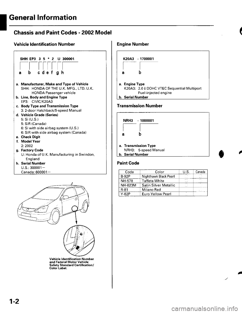
Chassis and Paint Codes - 2OO2 Model
Vehicle ldentffi cation Number
SHHEP3 35'2 U 300001
[[tttrtF
cdef gh
a. Manufacturer, Make and Type of Vehicle
SHH; HONDAOFTHE U.K. MFG., LTD. U.K.
HONDA Passenger vehicle
b. Line, Body and Engine Type
EP3: CIVIC/K20A3
c. Body Type and Transmission Type
3: 2-door HatchbacUs-speed Manual
d. Vehicle Grade lSeries)
5: Si {U.S.}
5; SiR (Canada)
6: Si with side airbag system (U,S.)
6: SiR with side airbag system (Canada)
e. Check Digit
l. ModelYear
2i 2002
g. Factory Code
U: Honda of U.K. Manufacturing in Swindon,
E ng land
h. Serial Number
U.S,: 300001 -
1-
V€hicle ldentif ication Numbo.and Federal Motor VehicleSaf ety Standard Certif ication/Color Label.
1-2
I
1700001K2OA3
a
a. Engine Type
K20A3: 2.0 0 DOHC VTEC Sequential Multiport
Fuel-injected engine
b. Serial Number
Engine Number
Transmission Number
Paint Code
CodeColoru.s.Canada
B-92PNiqhthawk Black Pearl
NH-578Taffeta White
NH-623MSatin Silver lvletallic
R-81Milano Red
Y-62PEuro Yeliow Pearl
NBH3
I
a
Transmission Type
NRH3; s-sDeed Manual
1000001
t0
Page 5 of 1139
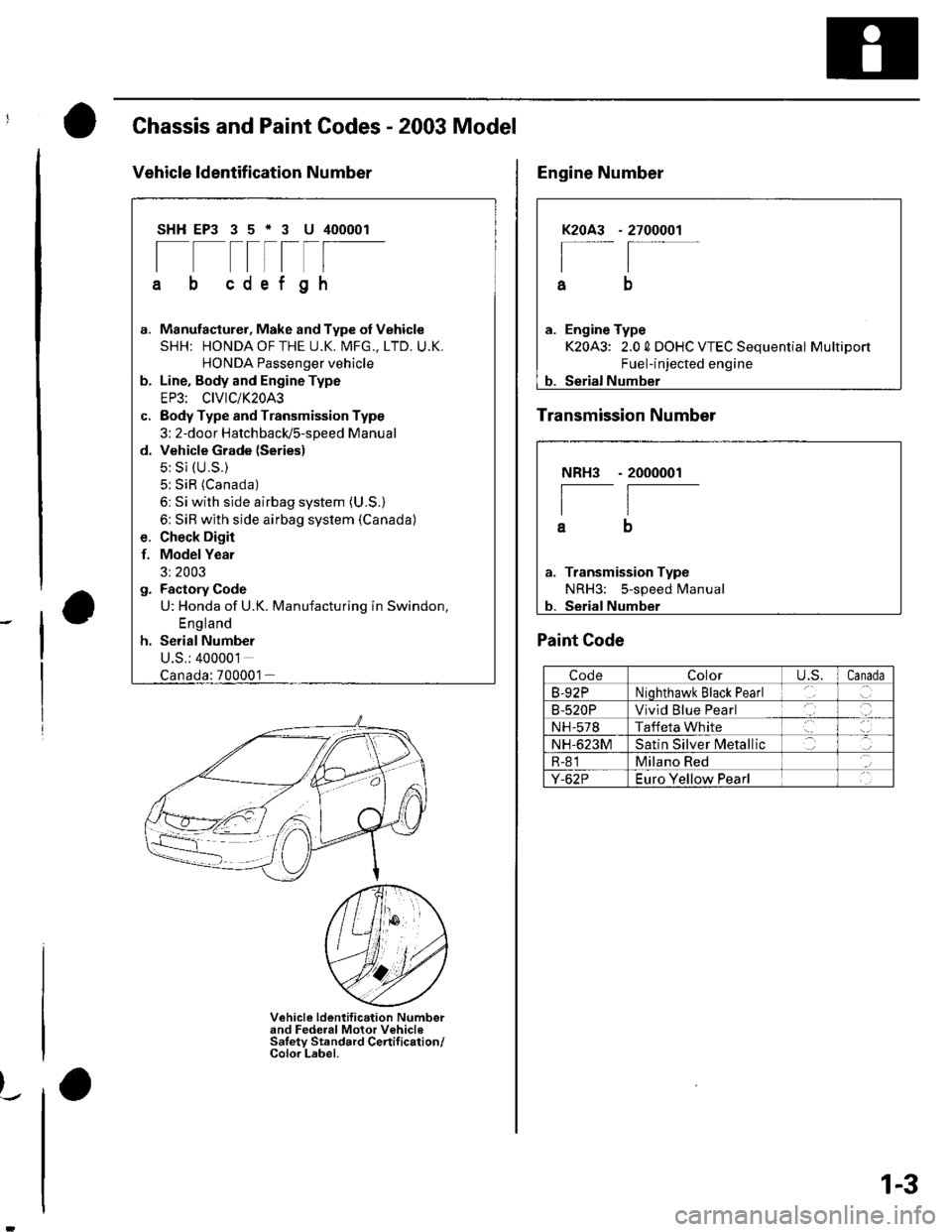
Chassis and Paint Codes - 2003 Model
Vehicle ldentif ication Number
SHHEP3 35*3 U 400001
[--t-rlF
cdef gh
G.
d.
Manufacturer, Make and Type of Vehicle
SHH: HONDAOFTHE U.K. MFG., LTD. U.K.
HONDA Passenger vehicle
Line. Body and Engine Type
EP3: CIVIC/K20A3
Body Type and Transmission Type
3: 2-door HatchbacldS-speed Manual
Vehicle Grade (Series)
5: Si (U.S.)
5: SiR (Canada)
6: Si with side airbag system (U.S.)
6: SiR with side airbag system (Canada)
Check Digir
Model Year
3: 2003
Factory Code
U: Honda of U.K. Manufacturing in Swindon,
England
Serial Number
U.S.: 400001
f.
:700001
Vehicle ldentification Numberand Federal Motor VehicleSaletv Standard Certif ication/Color Label.
)_.
2700001K2OA3
I
a
a. Engine Type
K20A3: 2.0 0 DOHC VTEC Sequential Multiport
Fuel-injected engine
b. Serial Number
Engine Number
Transmission Number
NRH3
I
a
Transmission Type
NRH3: 5-speed Manual
Serial Number
- 2000001
Paint Code
CodeColorU,S.Canada
B-92PNiohthawk Black Pearl
B-520PVivid Blue Pearl
NH-578Taffeta White
NH-623MSatin Silver N4etallic
R-81Milano Red
Y-62PEuro Yellow Pearl
1-3
Page 9 of 1139
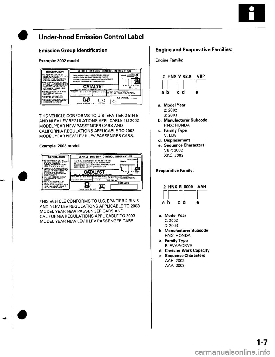
Under-hood Emission Control Label
Emission Group ldentif ication
Example: 2002 model
THIS VEHICLE CONFORMS TO U.S. EPA TIER 2 BIN 5
AND NLEV LEV REGULATIONS APPLICABLE TO 2002
MODEL YEAR NEW PASSENGER CARS AND
CALIFORNIA REGULATIONS APPLICABLE TO 2OO2
MODEL YEAR NEW LEV Ii LEV PASSENGER CARS.
Example: 2003 model
THIS VEHICLE CONFORMS TO U.S. EPA TIER 2 BIN 5
AND NLEV LEV REGULATIONS APPLICABLE TO 2O03
MODEL YEAR NEW PASSENGER CARS AND
CALIFORNIA REGULATIONS APPLICABLE TO 2OO3
MODEL YEAR NEW LEV II LEV PASSENGER CARS,
rH/ @
Engine and Evaporative Families:
Engine Family:
Model Year
2:2002
3: 2003
Manulacturer Subcode
HNX: HONDA
Family Type
V: LDV
Displacement
Sequence Characters
VBP: 2002
XKC: 2003
Evaporative Family:
2 HNX R OO99 AAH
t[-l=[
ab cd
Model Year
2t 2002
3: 2003
Manufacturer Subcode
HNX: HONDA
Family Type
R: EVAP/ORVR
Canister Work Capacity
Sequence Charactets
AAH: 2002
AAA: 2003
2 HNX V O2.O VBP
rr-tt--[ttl
ab cd e
c.
d.
e.
c.
d.
e.
1-7
Page 40 of 1139
Starter Circuit Troubleshooting
NOTE:. Airtemperature must be between 59'and 100'F (15'
and 38'C) during this procedure.
. After this test, or any subsequent repair, reset the
engine controle module (ECM) to clear any diagnostlc
trouble codes (DTCS) {see page 11-4).. The battery must be in good condition and fully
charged.. lf you disconnect the baftery, do the ECM idle learn
procedure (see page 11-139).
Recommended Procedure:. Use a starter system tester.. Connect and operate the equipment in accordance
with the manuf acturer's instructions.
Alternate Procedure
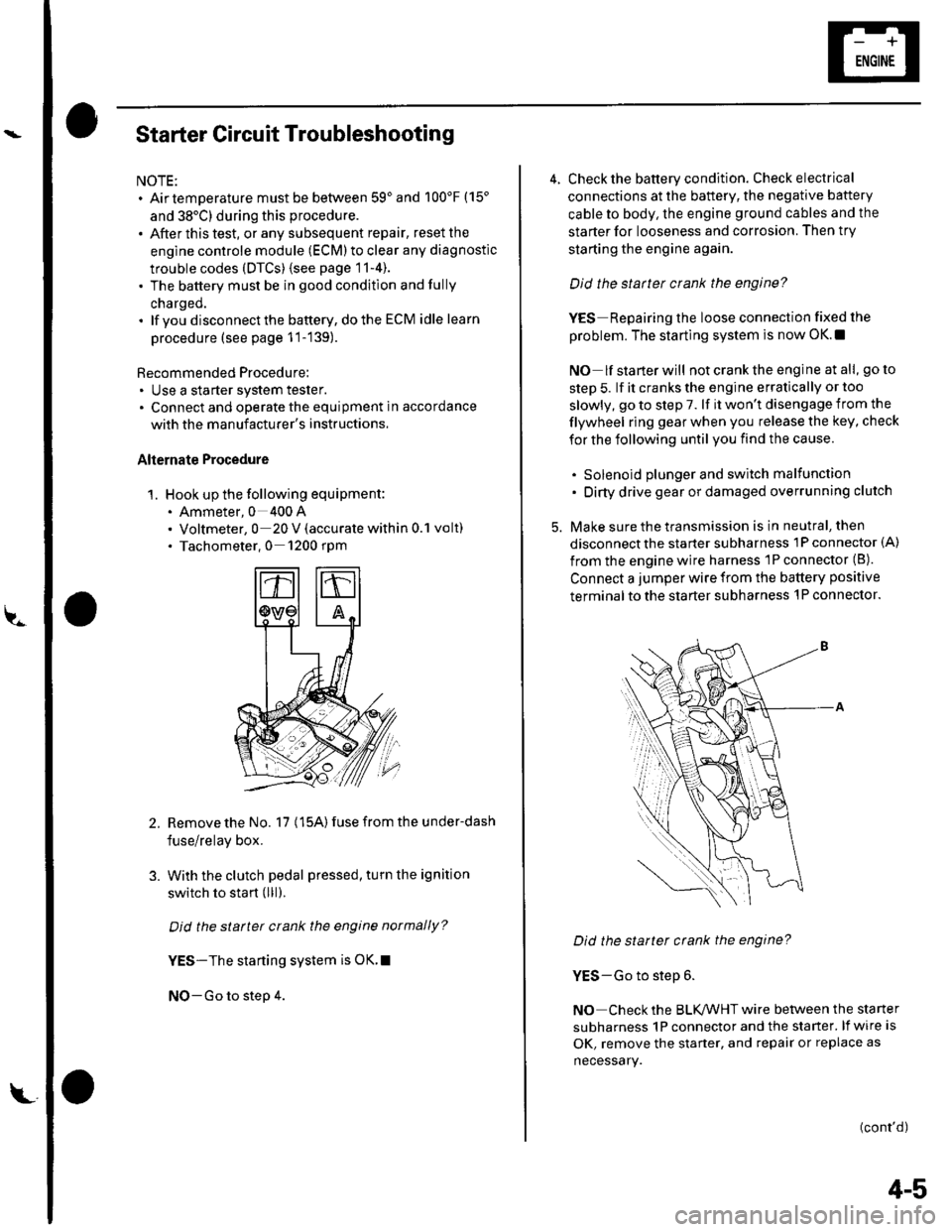
1. Hook up the following equipment:. Ammeter, 0 400 A. Voltmeter, 0 20 V (accurate within 0.1 volt). Tachometer,0 1200 rpm
2.Remove the No. 17 (15A) fuse from the under-dash
fuse/relay box.
With the clutch pedal pressed, turn the ignition
switch to start (lll).
Did the starter crank the engine normally?
YES-The starting system is OK.I
NO-Go to step 4.
3.
L
4-5
4. Check the battery condition. Check electrical
connections at the battery, the negative baftery
cable to body, the engine ground cables and the
starter for looseness and corrosion. Then try
starting the engine again.
Did the statter crank the engine?
YES Repairing the loose connection fixed the
problem. The starting system is now OK.!
NO lf starterwill notcranktheengine atall, goto
step 5. lf it cranks the engine erratically or too
slowly, go to step 7. lf it won't disengage from the
flywheel ring gear when you release the key, check
for the following until you find the cause.
. Solenoid plunger and switch malfunction. Dirty drive gear or damaged overrunning clutch
5. Make sure the transmission is in neutral, then
disconnect the starter subharness 1P connector (A)
from the engine wire harness 'lP connector (B).
Connect a jumper wire from the battery positive
terminal to the starter subharness 'l P connector.
Did the starter crank the engine?
YES-Go to step 6.
NO Check the BLK,ANHT wire between the starter
subharness 1P connector and the starter. lf wire is
OK, remove the starter, and repair or replace as
necessary.
(cont'd)
Page 44 of 1139
Starter Replacement
1. Make sure you have the anti-theft code for the radio.
then write down the frequencies for the radio's
preset buttons.
2. Disconnect the negative cable from the battery first,
then disconnect the positive cable.
3. Disconnect the knock sensor connector.
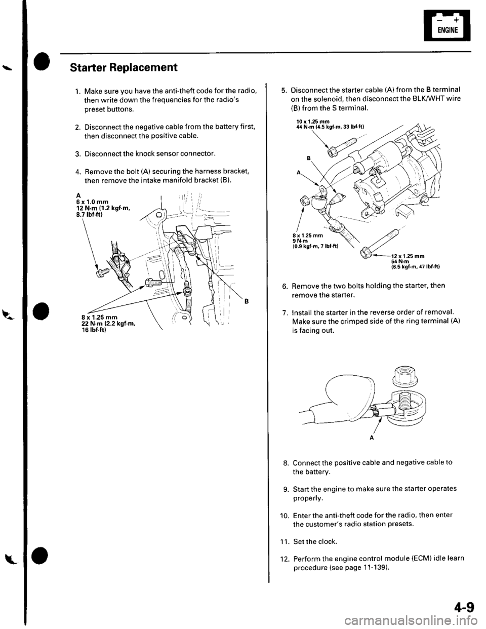
4. Remove the bolt (A) securing the harness bracket,
then remove the intake manifold bracket (B).
A6x1,0mm12 N.m {1.2 kgf.m,8.7 tbt.ft)
8 x 1.25 mm22 N,m 12.2 kgt.m,16 rbf.ftl
L't2.
4-9
5. Disconnect the starter cable (A)from the B terminal
on the solenoid, then disconnect the BLK,/WHT wire
{B) from the S terminal.
10 x 1.25 mm44 N.m {a.5 kgf.m,33lblft)
8 x 1.25 mm9Nm10.9 kgf.m,7 lbl ft)
7.
9.
'10.
11.
2
S'-12x12smm6ilNm{6.5 kgl m,47lbfft)
Remove the two bolts holding the starter, then
remove the starter.
lnstall the starter in the reverse order of removal.
Make sure the crimped side of the ring terminal (A)
is facing out.
Connect the positive cable and negative cable to
the batterY.
Start the engine to make sure the starter operates
propeny.
Enter the anti-theft code for the radio, then enter
the customer's radio station presets.
Set the clock.
Perform the engine control module (EcM) idle learn
procedure (see page 1 '1- 139 ).
I
Page 57 of 1139
Gharging System
Charging Circuit Troubleshooting
lf the charging system indicator does not come on or
does not go off, or the battery is dead or low, test these
items in the order listed below:
Battery (see page 22-50)
Charging system indicator
Alternator and regulator circuit
Alternator control system
Charging System Indicator Test
1. Turn the ignition switch ON {ll).
Does the chatging system indicator come on?
YES Go to step 2.
NO Go to step 3.
2. Start the engine.
Does the charging system indicator go off?
YES-Charging system indicator circuit is OK. Go
to the Alternator and Regulator circuit Test. t
NO-Go to step 3.
3. Turn the ignition switch OFF.
4. Troubleshoot the multiplex control system (see
page 22 172).
ls the multiplex control system OK?
YES Go to step 5.
NO Check the multiplex control system as
indicated by the diagnostic trouble code (DTC) (see
step 8 on page 22-172).1
5. Disconnect the engine wire harness 6P connector
from the starter sub harness 6P connector.
4-22
\"4
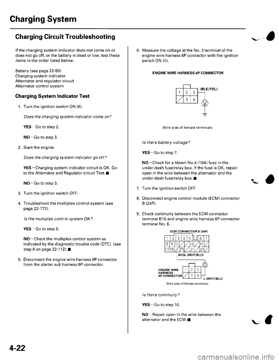
6. Measure the voltage at the No. 3 terminal of the
engine wire harness 6P connector with the ignition
switch ON { ll).
ENGINE WIRE HARNESS 6P CONNECTOR
IBLK/YEL}
Wire side of female terminals
ls there battery voltage?
YES-Go to step 7.
NO-Check for a blown No.4 {10A) fuse in the
under-dash fuse/relay box. lf the fuse is OK, repair
open in the wire between the alternator and the
under-dash fuse/relay box. I
Turn the ignition switch OFF.
Disconnect engine control module (ECM) connector
B (24P).
Check continuity between the ECM connector
terminal B'10 and engine wire harness 6P connector
terminal No. 6.
?
7.
8.
9.
ACGL {WHT/BLU)
ENGINE WIBEHARNESS6PL (WHT/BLUI
Wire side of femaletermina s
ls there continuity?
YES Go to step 10.
NO-Repair open in the wire between the
alternator and the ECN4.I
ECM CONNECTOB A (24P)
Page 64 of 1139
l\-Alternator Replacement
1. Make sure you have the anti-theft code for the radio,
then write down the frequencies for the radio'spreset buttons,
2. Disconnect the negative cable from the battery first,
then disconnect the positive cable.
3. Remove the front bumper (see page 20-85).
4. Remove the right side headlight (see page 22-79).
5. Remove the reserve tank from the bracket.
6. Remove the drive belt (see page 4-26).
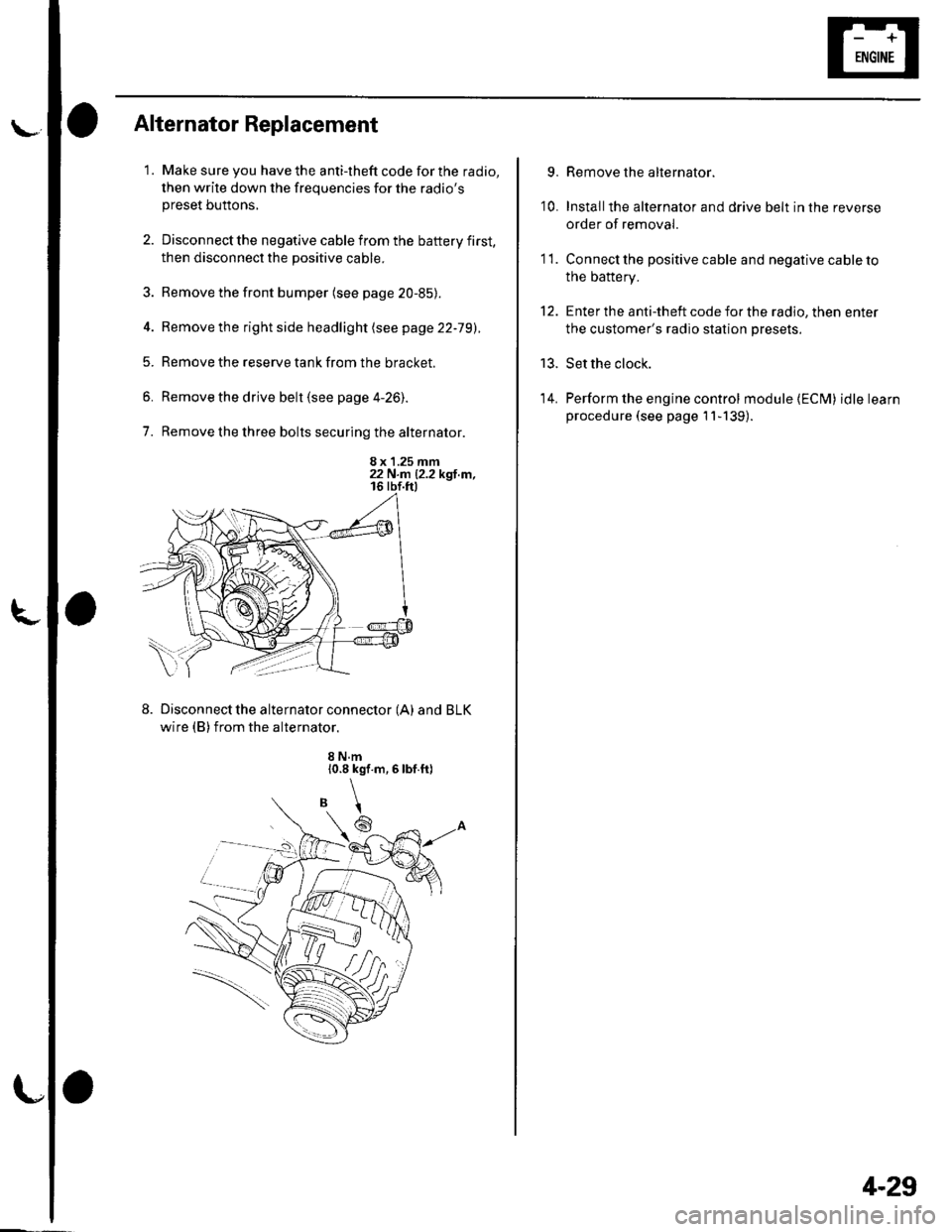
7. Remove the three bolts securing the alternator.
8 x 1.25 mm22 N.n 12.2 kgl.m,
Disconnect the alternator connector (A) and BLK
wire (B) from the alternator.
8 N.m10.8 kgf.m,6lbf.ft)
\
6
'I 1.
9.
10.
13.
14.
Remove the alternator.
Installthe alternator and drive belt in the reverse
order of removal.
Connect the positive cable and negative cable to
the battery.
Enter the anti-theft code for the radio, then enter
the customer's radio station presets.
Set the clock.
Perform the engine control module {ECM) idle learn
procedure (see page 11-139).
tt.
4-29
Page 82 of 1139
Engine Assembly
I
Engine Removal
Special Tools Required
Front subframe adapter EOS02C00001 1
NOTE:. Use fender covers to avoid damaging painted
surfaces.. To avoid damage, unplug the wiring connectors
carefully while holding the connector portion.. Mark all wiring and hoses to avoid misconnection.
Also, be sure that they do not contact other wiring orhoses, or interfere with other parts.
1. Secure the hood in the wide open position (support
rod in the lower hole).
2. Make sure you have the anti-theft code for the radio,
then write down the frequencies for the radio'spreset buttons.
3. Disconnect the negative cable from the battery first,then disconnect the positive cable.
4. Remove the battery.
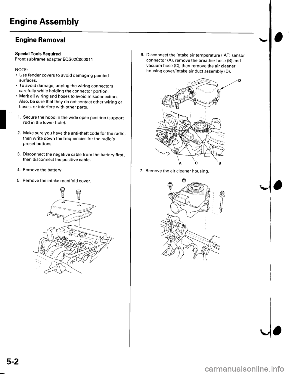
5. Remove the intake manifold cover.
II
5-2
\,
6. Disconnectthe intake airtemperature (lAT) sensorconnector (A), remove the breather hose (B) and
vacuum hose (C), then remove the air cleaner
housing cover/intake air duct assemblv (D).
AC
7. Remove the air cleaner housing.
Page 95 of 1139
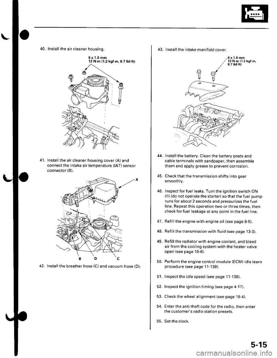
40. Install the air cleaner housinq.
6x1.0mm12 N m (1.2 kgf.m,8.7 lbt.ft)
Install the air cleaner housing cover (A) and
connect the intake air temperature (lAT) sensor
connector (B),
42. Installthe breather hose (C) and vacuum hose 1D).
41.
43. Installthe intake manifold cover.
6x1.0mm12Nm11.2kgf.m.8.7 tbf.ft)
Installthe battery. Clean the battery posts and
cable terminals with sandpaper, then assemble
them and apply grease to prevent corrosion.
Check that the transmission shifts into gear
smoothly.
Inspect for fuel leaks. Turn the ignition switch ON(ll) {do not operate the starter) so that the fuel pump
runs for about 2 seconds and pressurizes the fuel
line. Repeat this operation two or three times, then
check for fuel leakage at any point in the fuel line.
Refillthe engine with engine oil (see page 8-5).
Refill the transmission with fluid (see page 13-3).
Refill the radiator with engine coolant, and bleed
air from the cooling system with the heater valve
open (see page 10-6).
Perform the engine control module (ECM) idle learnprocedure (see page 11-139).
Inspect the idle speed (see page 1 1-138).
Inspect the ignition timing (see page 4-17).
Check the wheel alignment {see page 18-4).
Enter the anti-theft code for the radio, then enter
the customer's radio station presets.
Set the clock.
YE
44.
41.
]tE
46.
48.
49.
52.
53.
54.
50.
51.
55.
5-15