code HONDA CIVIC 2003 7.G User Guide
[x] Cancel search | Manufacturer: HONDA, Model Year: 2003, Model line: CIVIC, Model: HONDA CIVIC 2003 7.GPages: 1139, PDF Size: 28.19 MB
Page 144 of 1139
Engine Block
Crankshaft Main Bearing Replacement
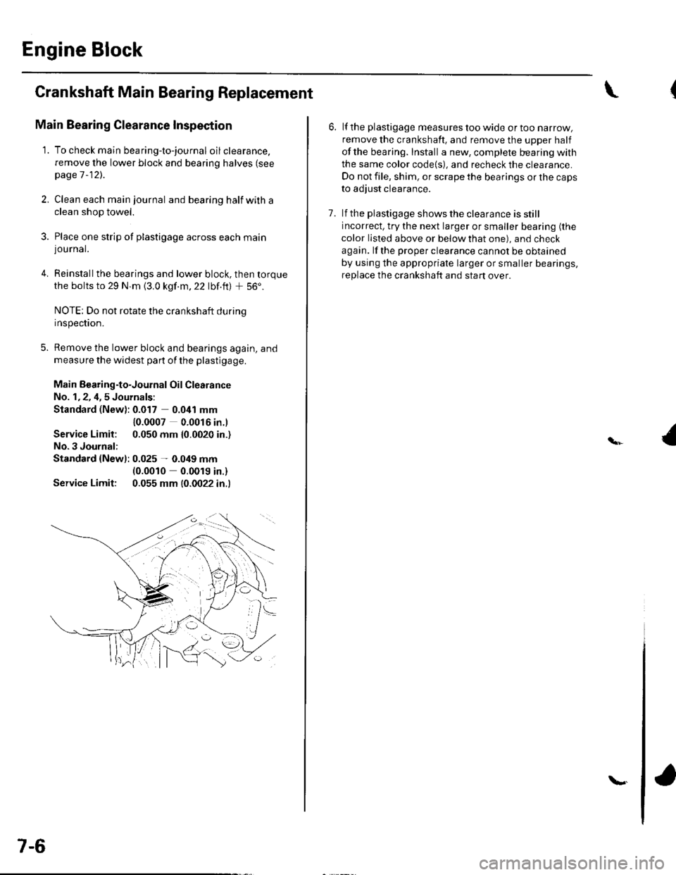
Main Bearing Clearance Inspection
1. To check main bea ring-to-jou rna I oil clearance.
remove the lower block and bearing halves (see
page 1 -12)..
2, Clean each main journal and bearing half witha
clean shop towel.
3. Place one strip of plastigage across each main
lou rnal.
4. Reinstallthe bearings and lower block, then torque
the bolts to 29 N.m {3.0 kgf.m,22 lbf.ft) + 56'.
NOTE: Do not rotate the crankshaft during
Inspeclton.
5. Remove the lower block and bearings again, and
measure the widest part of the plastigage.
Main Bearing-to-Journal Oil Clearance
No. 1,2, 4,5 Journals:
Standard (New): 0.017 0.041 mm
Service Limit:
No.3 Journal:
10.0007 0.0016 in.l
0.050 mm {0.0020 in.)
Standard {Newl: 0.025 - 0.049 mm(0.0010 0.0019 in.)
Service Limit: 0.055 mm (0.0022 in.l
7-6
\.
6. lf the plastigage measures too wide or too narrow,
remove the crankshaft. and remove the upper half
ofthe bearing. Install a new, complete bearing with
the same color code{s), and recheck the clearance.
Do not file, shim, or scrape the bearings or the caps
to adjust clearance.
7. lf the plastigage shows the clearance is still
incorrect, try the next larger or smaller bearing (the
color listed above or below that one), and check
again. lf the proper clearance cannot be obtained
by using the appropriate larger or smaller bearings,
replace the crankshaft and start over.
Page 145 of 1139
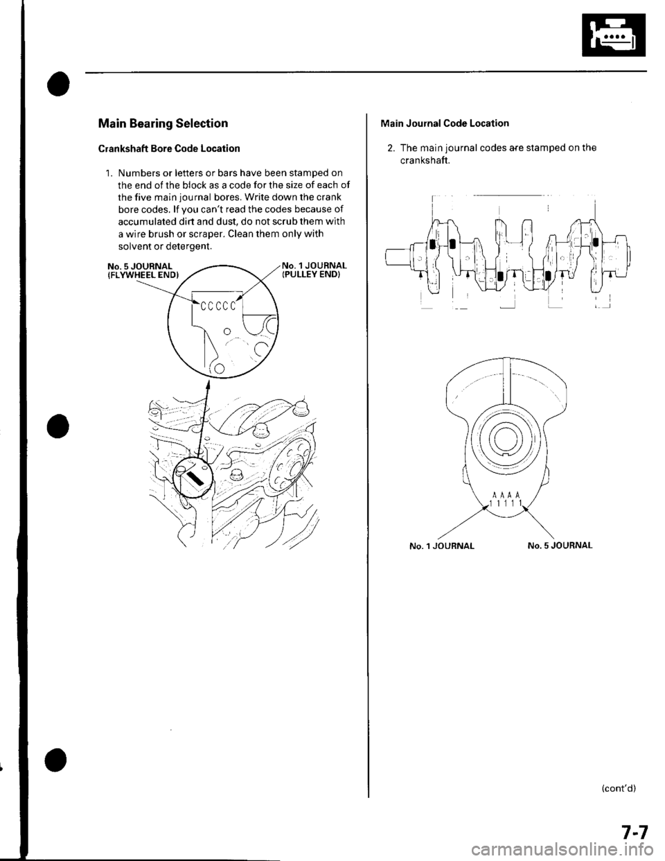
Main Bearing Selection
Crankshaft Bore Code Location
1. Numbers or letters or bars have been stamped on
the end of the block as a code for the size of each of
the five main journal bores. Write down the crank
bore codes. lf you can't read the codes because of
accumulated dirt and dust, do not scrub them with
a wire brush or scraper. Clean them only with
solvent or detergent.
No. 1 JOURNALIPULLEY END}No. 5 JOURNAL{FLYWHEEL END)
Main Journal Code Location
2. The main journal codes a{e stamped on the
cra n kshaft.
No. 1 JOURNALNo. 5 JOURNAL
(cont'd)
7-7
Page 146 of 1139
Engine Block
Crankshaft Main Bearing
Replacement (cont'd)
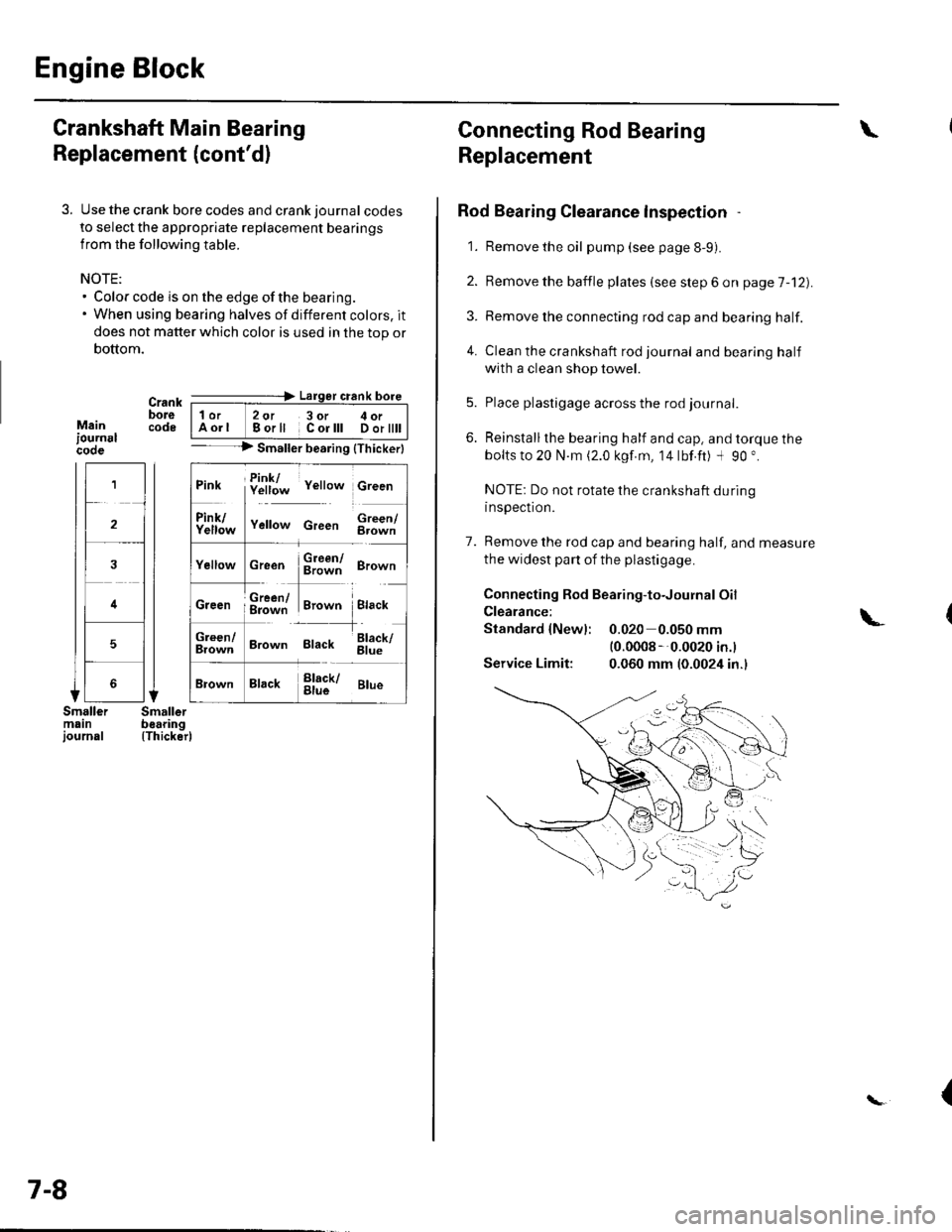
3. Use the crank bore codes and crank journal codes
to select the appropriate replacement bearings
from the following table.
NOTE:. Color code is on the edge of the bearing.. When using bearing halves of different colors. it
does not matter which color is used in the top or
bottom.
Mainiournslcooe
Crank ---=-> Lalger crank bore
bore | 1or 2ot 3or c oi__-lcode IAorl Borll Corlll Dortttt I-- --> Smaller bearing {Thickerl
(Thicker)
1
2
4
5
Pink f!1f;* v"rro* c,""n
ll
f111f;,," v"no* c,""" $;;fl
cr""n $ffi ero-n
ffi#Tr,.*" i.,""*Creen ; g=jiff;i Brown Black
;;lT]*
'---l-'o"*,
Brown Black 6il;
Brack !l;kr ar*
7-8
Connecting Rod Bearing
Replacement
Rod Bearing Clearance lnspection
1. Remove the oil pump (see page 8-9).
2. Bemove the baffle plates (see step 6 on page 7-12).
3. Remove the connecting rod cap and bearing half.
4. Clean the crankshaft rod journal andbearinghalf
with a clean shop towel.
5. Place plastigage across the rod journal.
6. Reinstallthe bearing half and cap, and torque the
bolts to 20 N.m (2.0 kgf.m, 14lbf.ft) -l 90 ".
NOTE: Do not rotate the crankshaft during
inspection.
7. Remove the rod cap and bearing half, and measure
the widest part of the plastigage.
Connecting Rod Bearing-to-Journal Oil
Clearance:
Standard {Newl: 0.020 0.050 mm(0.0008 --0.0020 in.l
Service Limit: 0.060 mm (0.0024 in.)
\
\-
{
Page 147 of 1139
8.
9.
lf the plastigage measures too wide or too narrow,
remove the upper half of the bearing, install a new,
complete bearing with the same color code(s), and
recheck the clearance. Do not file. shim, or scrape
the bearings or the caps to adjust clearance.
lf the plastigage shows the clearance is still
incorrect, try the next larger or smaller bearing (the
color listed above or below that one), and check
clearance agaln. lf the proper clearance cannot be
obtained by using the appropriate larger or smaller
bearing, replace the crankshaft and stan over.
Rod Bearing Selection
1. Inspect each connecting rod for cracks and heat
damage.
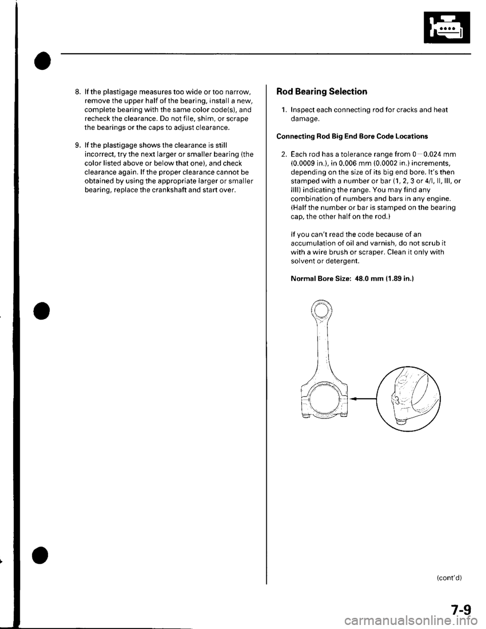
Connecting Rod Big End Eore Code Locations
2. Each rod has a tolerance range from 0 0.024 mm
(0.0009 in.), in 0.006 mm (0.0002 in.) increments,
depending on the size of its big end bore. lt's then
stamped with a number or bar (1, 2,3 or 4/1, ll,lll, ol
llll) indicating the range. You may find any
combination of numbers and bars in any engine.(Half the number or bar is stamped on the bearing
cap, the other half on the rod.)
lf you can't read the code because of an
accumulation of oil and varnish. do not scrub it
with a wire brush or scraper. Clean it only with
solvent or detergent.
Normal Bore Size: 48.0 mm 11.89 in.l
(cont'd)
7-9
Page 148 of 1139
Engine Block
Connecting Rod Bearing Replacement (cont'dl
Connecting Rod Journal Code Location
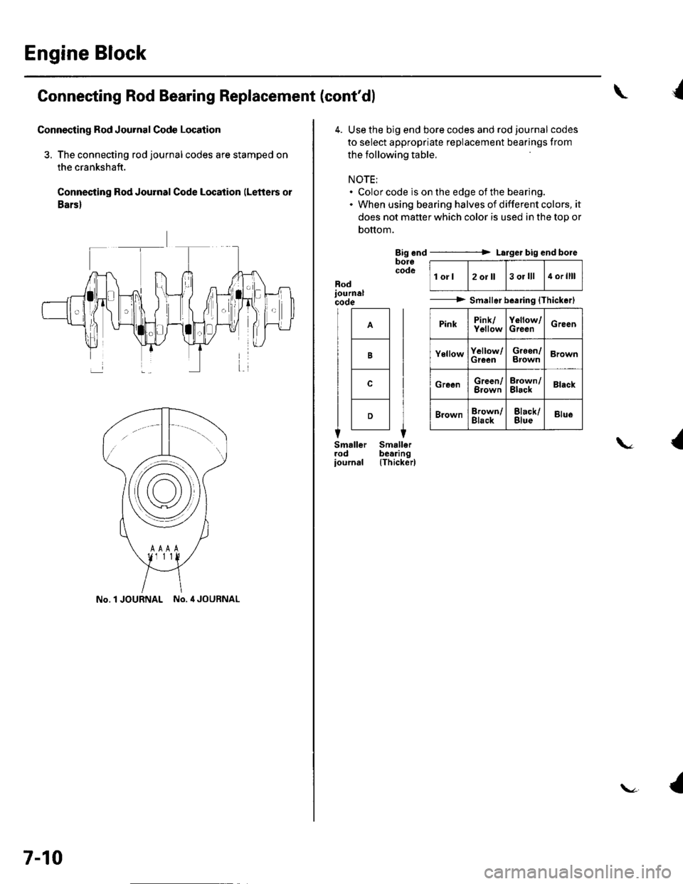
3. The connecting rod journalcodes are stamped on
the crankshaft.
Connecting Rod Journal Code Location (Letters or
Bars)
No.l JOURNAL No. 4 JOURNAL
7-10
\{
4. Use the big end bore codes and rod journalcodes
to select appropriate replacement bearings from
the following table.
NOTE:. Color code is on the edge of the bearing.. When using bearing halves of different colors, it
does not matter which color is used in the top or
bottom.
Big end ----------> Larger big end boreborecodolorl2oJll3 ol lll4 orllll
---------> Smallsrb.aring {Thickerl
PinkPink/YellowYollow/GrecnGreen
YellowYellow/GreenGreen/BrownBrown
GreenGreen/BrownErown/BlackBlack
BrownBrown/BlackBlack/BlueBlue
Rod
B
c
D
{\
(Thicker)
{
Page 208 of 1139
Fuel and Emissions
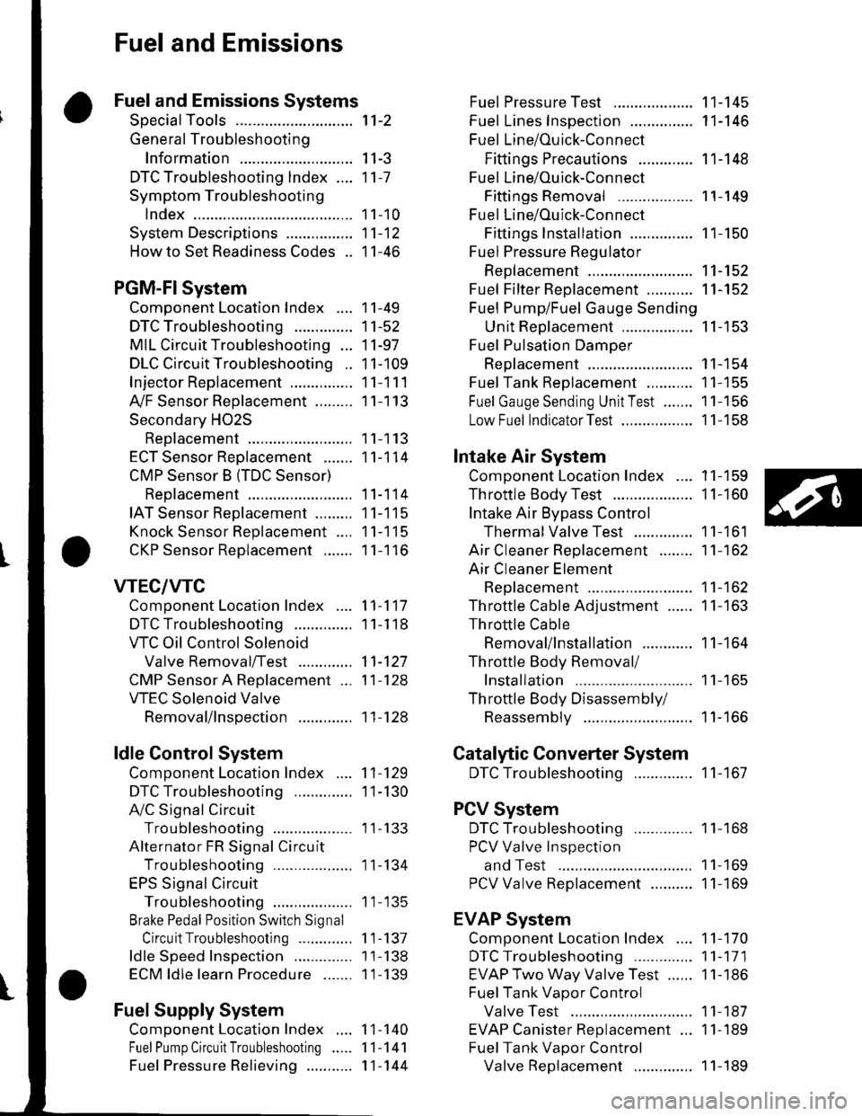
Fuel and Emissions Systems
SpecialTools
General Troubleshooting
Information
DTC Troubleshooting lndex ....
Symptom Troubleshooting
1ndex...............
System Descriptions ................
Howto Set Readiness Codes ..
PGM-FlSystem
Component Location Index ....
DTC Troubleshooting ..............
MIL Circuit Troubleshooting ...
DLC Circuit Troubleshooting ..
Injector Replacement ...............
A,/F Sensor Replacement .........
Secondary HO2S
Replacement
ECT Sensor Reolacement .......
CMP Sensor B {TDC Sensor)
Replacement
IAT Sensor Replacement .........
Knock Sensor Replacement ....
CKP Sensor Reolacement .......
VTEC/VTC
Comoonent Location Index ....
DTC Troubleshooting ..............
VTC Oil Control Solenoid
Valve Removal/Test .............
CMP Sensor A Replacement ...
VTEC Solenoid Valve
Removal/lnsoection .............
ldle Control System
Component Location Index
DTC Troubleshooting ..............
A,/C Signal Circuit
TroubleshootinS ...................
Alternator FR Signal Circu it
TroubleshootinS ...................
EPS Signal Circuit
TroubleshootinS ...................
Brake Pedal Position Switch Signal
Circuit Troubleshooting .............
ldle Speed Inspection
ECM ldle learn Procedure .......
Fuel Supply System
Component Location Index
Fuel Pump Circuit Troubleshooting
1't-2
I I-J
11-7
1 1-10
11-12
11-46
11-49
11-52
11-97
11-109
11-111
11-113
11-113
11-114
11-114
11-115
11-115
11-116
11-117
1 1-1 18
11-127
11-128
11-128
11-129
1I-130
I t- t55
11-134
1 1- 135
1 1-137
1 1-138
1 1-139
1 1-140
11-141
11-144
Fuel PressureTest ................... 11-145
Fuel Lines Inspection ............... 11-146
Fuel Line/Ouick-Connect
Fittings Precautions ............. 1 1-148
Fuel Line/Ou ick-Con nect
Fittings Removal .................. 1 1-149
Fuel Line/Ou ick-Con nect
Fittings lnstallation ............... 11-150
Fuel Pressure Regu lator
Replacement ......................... 11-152
Fuel Fifter Replacement ........... 11-152
Fuel Pump/Fuel Gauge Sending
UnitReDlacement ................. 11-153
Fuel Pulsation Damoer
Rep1acement ......................... 11-154
Fuel Tank Reolacement ........... 11-155
Fuel GaugeSending UnitTest ....... 11-156
Low Fuel lndicatorTest ................. 1 1-158
Intake Air System
Comoonent Location Index .... 11-159
Throttle BodyTest ................... 11-160
Intake Air Bypass Control
Thermal Valve Test .............. 11-161
Air Cleaner Reolacement ........ 11-162
Air Cleaner Element
Reolacement ......................... 11-162
Throttle Cable Adjustment ...... 11-163
Th rottle Cable
Removal/lnstallation ............ 1 1-164
Th rottle Body Removal/
Installation .. 11-165
Th rottle Body Disassembly/
Reassemblv .......................... 11-166
Catalytic Converter System
DTC Troubleshooting .............. 1 1-167
PCV System
DTC Troubleshooting .............. 1 1-168
PCV Valve InsDection
and Test ...... 1 1- 169
PCV Valve Reolacement .......... 11-169
EVAP System
Component Location Index .... 11-170
DTCTroubleshooting .............. 11-171
EVAP Two Way Valve Test ...... 11-186
Fuel Tank Vaoor Control
Valve Test ... 11-187
EVAP Canister Replacement ... 11-189
Fuel Tank Vaoor Control
Valve Reolacement .............. 1 1-189Fuel Pressu re Relieving ...........
Page 210 of 1139
General Troubleshooting Information
Intermittent Failures
The term "intermittent failure" means a svstem mav
have had a failure. but it checks OK now. lf the
Malfunction Indicator Lamp (MlL) on the dash does not
come on, check for Door connections or loose terminals
at all connectors related to the circuit that Vou are
troubleshooting.
Opens and Shorts
"Ooen" and "Short" are common electrical terms. An
open is a break in a wire or at a connection. A short is
an accidental connection of a wire to ground or to
another wire. In simple electronics, this usually means
something won't work at all. With complex electronics(such as ECMs)this can sometimes mean something
works, but not the way it's supposed to.
How to Use the PGM Tester or a Scan Tool
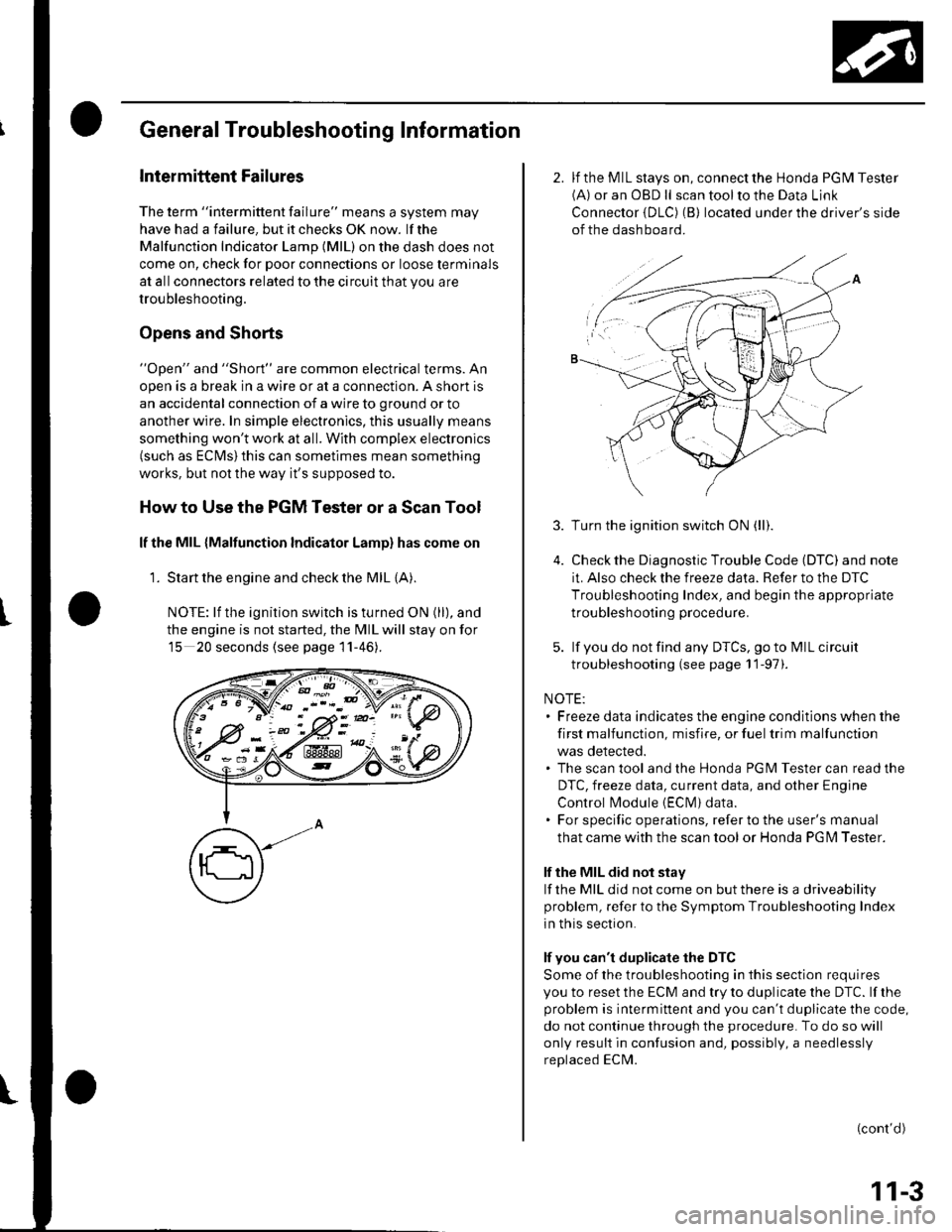
lf the MIL {Malfunction Indicator Lamp} has come on
'1. Start the engine and check the MIL {A).
NOTE: lf the ignition switch is turned ON (ll), and
the engine is not started, the MIL will stay on for
15 20 seconds (see page 11-46).
K-> ;"PN/.- -::: - -d V-: !
w:ix&K#
2. lf the MIL stays on, connect the Honda PGM Tester(A) or an OBD ll scan tool to the Data Link
Connector {DLC) (B) located under the driver's side
of the dashboard.
3.
5.
Turn the ignition switch ON (ll).
Check the Diagnostic Trouble Code (DTC) and note
it. Also check the freeze data. Refer to the DTC
Troubleshooting Index, and begin the appropriate
troubleshooting procedure.
lf you do not find any DTCS, go to MIL circuit
troubleshooting (see page 11-97).
NOTE:. Freeze data indicates the engine conditions when the
first malfunction, misfire, or fuel trim malfunction
was detected.. The scan tool and the Honda PGM Tester can read the
DTC, freeze data, current data, and other Engine
Control l\4odule {EClvl) data.. For specific operations, refer to the user's manual
that came with the scan tool or Honda PG l\4 Tester.
lf the MIL did not stay
lf the MIL did not come on but there is a driveability
problem, refer to the Symptom Troubleshooting Index
in this section.
lf you can't duplicate the DTC
Some of the troubleshooting in this section requires
you to reset the ECM and try to duplicate the DTC. lf rhe
problem is intermittent and you can't duplicate the code,
do not continue through the procedure. To do so will
only result in confusion and, possibly, a needlessly
replaced ECM.
(cont'd)
11-3
Page 211 of 1139
Fuel and Emissions Systems
General Troubleshooting Information (cont'dl
How to Reset the ECM
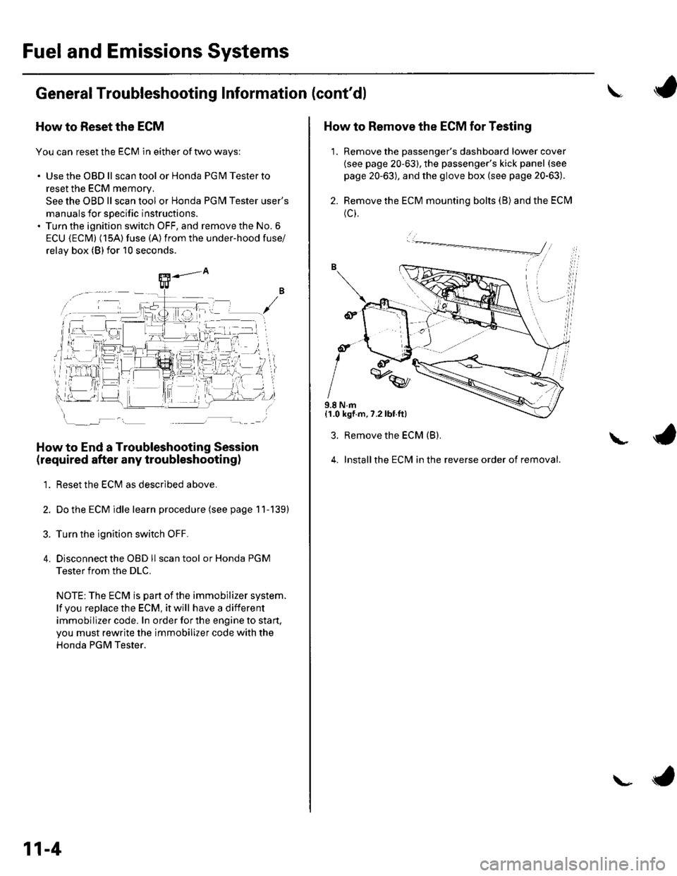
You can reset the ECM in either of two ways:
. Use the OBD ll scantool or Honda PGMTesterto
reset the ECM memory.
See the OBD ll scan tool or Honda PGI\4 Tester user's
manuals for specific instructions.' Turn the ignition switch OFF, and remove the No. 6
ECU {ECM} (15A) fuse (A)from the under-hood fuse/
relav box (Blfor 10 seconds.
How to End a Troubleshooting Session
(required after any troubleshootingl
1. Reset the ECM as described above.
2. Do the ECM idle learn procedure (see page 11-139)
3. Turn the ignition switch OFF.
4. Disconnectthe OBD ll scan tool or Honda PGM
Tester from the DLC.
NOTE: The ECM is part of the immobilizer system.
lf vou replace the ECM, it will have a different
immobilizer code. In order for the engine to start,
you must rewrite the immobilizer code with the
Honda PGM Tester.
11-4
\- ta
J
How to Remove the ECM for Testing
1. Remove the passenger's dashboard lower cover
{see page 20-63), the passenger's kick panel (see
page 20-63), and the glove box (see page 20-63).
2. Remove the ECM mounting bolts (B) and the ECM
(c),
9.8 N.m{1.0 kgf.m,7.2lbt.ft}
3. Remove the ECM (B).
4. Installthe ECM in the reverse order of removal.
L
Page 213 of 1139
Fuel and Emissions Systems
General Troubleshooting Information (cont'd)
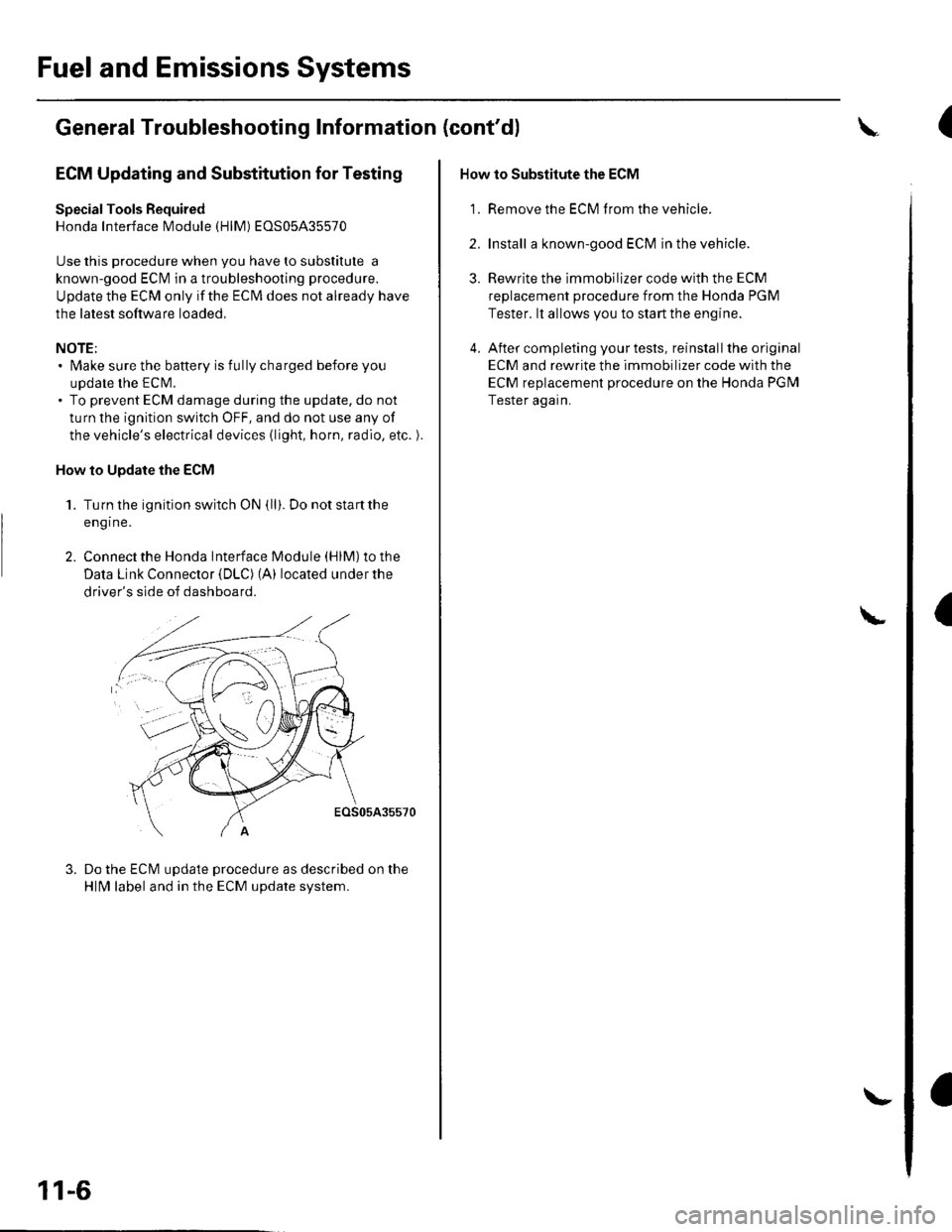
ECM Updating and Substitution for Testing
Special Tools Bequired
Honda Interface Module (HlM) EOS05435570
Use this procedure when you have to substitute a
known-good ECM in a troubleshooting procedure.
U pdate the ECM only if the ECN4 does not already have
the latest software loaded,
NOTE;. lMake sure the battery is fully charged before you
update the ECN4.. To prevent ECM damage during the update, do not
turn the ignition switch OFF, and do not use any of
the vehicle's electrical devices (light, horn, radio, etc. ).
How to Update the ECM
1. Turn the ignition switch ON (ll). Do not startthe
eng Ine.
2. Connect the Honda lnterface Module (HlM) to the
Data Link Connector {DLC) (A) located under the
driver's side of dashboard.
EOS05A35570
Do the ECM update procedure as described on the
HlN4 label and in the ECM update system.
11-6
\-
How to Substitute the ECM
'1. Remove the ECM f rom the vehicle.
2. Install a known-good ECM in the vehicle.
3. Rewrite the immobilizer code with the ECM
replacement procedure from the Honda PGM
Tester. lt allows you to start the engine.
4. After completing your tests, reinstall the original
ECM and rewrite the immobilizer code with the
ECM replacement procedure on the Honda PGM
Tester again.
L
(
I
Page 217 of 1139
Fuel and Emissions Systems
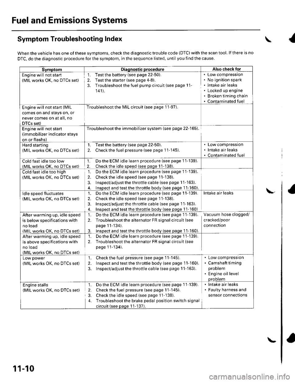
Symptom Troubleshooting Index
When the vehicle has one of these symptoms, check the diagnostic trouble code (DTC) with the scan tool. lf there is no
DTC, do the diagnostic procedure for the symptom, in the sequence listed, until you find the cause.
SvmotomDiaqnostic procedureAlso check lor
Engine will not sta rt
(MlL works OK, no DTCS set)
1. Test the battery {see page 22-50).
2. Test the starter (see page 4-8).
3. Troubleshoot the fuel pump circult (see page 11
141).
Low compressron
No ignition spark
lntake air leaks
Locked up engine
Broken timing chain
Contaminated fuel
Engine will not start (MlL
comes on and stays on, or
never comes on at all, no
DTCS set)
Troubleshoot the l\4lL circuit (see page 1 '1-97).
Engine will not start
(immobilizer indicator stays
on or flashs)
Troubleshoot the immobilizer system (see page 22-165).
Hard starting(MlL works OK, no DTCS set)
1. Testthe battery (see page 22-50).
2. Checkthe fuel pressure (see page 11-145).
Low compression
Intake air leaks
Contaminated fuel
Cold fast idle too low(MlL works OK. no DTCS set)
1. Do the ECM idle learn procedure (see page 11-139).
2. Checkthe idle sDeed (see paqe 11-138).
Cold fast idle too high
(MlL works OK, no DTCS set)
Do the ECI\4 idle learn procedure (see page 1 1- 139).
Checkthe idle speed {see page 11-138).
Inspect/adjust the throttle cable (see page 1 '1-'163).
Inspect and test the throttle body {see page 1 1-160}.
']�
2.
3.
ldle speed fluctuates
(MlL works OK, no DTCS set)
1. Dothe ECM idle learn procedure (see page 11-'139).
2. Check the idle speed (see page 11-138).
3, Inspecvadjust th e throttle cable (see page 11''163).
4. Insoect and test the throttle bodv (see paqe 11- 160)
Intake air leaks
After warming up, idle speed
is below specifications with
no load
{MlL works OK, no DTCS set)
1. Do the ECIVI idle learn procedure (see page 1 1- 139).
2. Troubleshootthe alternator FR signal circuit (see
page 11-'134).
3. InsDect and test the throttle bodv {see paqe 1 1-160).
Vacuum hose clogged/
cracked/poor
connectron
After warming up, idle speed
is above specifications with
no toao(MlL works OK. no DTCS set)
1. Do the ECM idle learn procedure {see page 1'j-139).
2. Troubleshoot the alternator FR signal circuit(see
page 11-134).
Low power
(MlL works OK, no DTCS set)
1. Check the fuel pressure(seepagell-145).
2. Inspect and test the th roftle body (see page 11-160).
3. Inspecvadjust the throttle cable (see page 11-'163).
Low compressron
Camshaft timing
problem
Engine oil levelprootem
Engine stalls(MlL works OK. no DTCS set)
1. Do the ECM idle learn procedure (see page 1'l'139).
2. Check the fuel pressure{seepagell-145).
3. Check the idle speed (see page I 1-138).
4. Troubleshootthe brake pedal position switch signal
circuit (see paqe 11-137).
lntake air leaks
Faulty harness and
sensor connections
\
\-
11-10
\-