idle control HONDA CIVIC 2003 7.G Workshop Manual
[x] Cancel search | Manufacturer: HONDA, Model Year: 2003, Model line: CIVIC, Model: HONDA CIVIC 2003 7.GPages: 1139, PDF Size: 28.19 MB
Page 35 of 1139
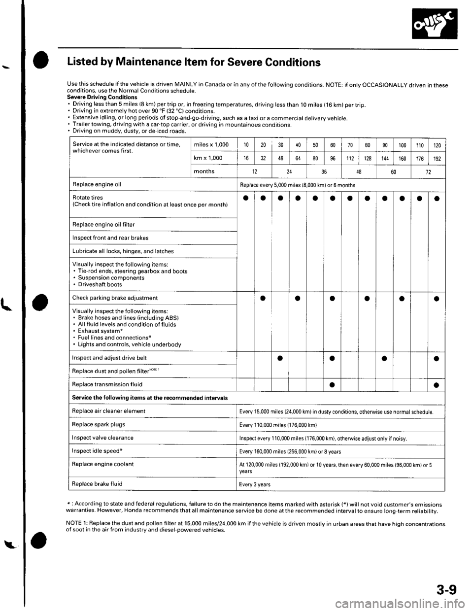
Listed by Maintenance ltem for Severe Conditions
Use this schedule if the vehicle is driven MAINLY in Canada or in anv of the followina conditions.NOTE: it only OCCASIONALLY driven in theseconditions, use the Normal Conditions schedute.Sovere Driving Conditions. Driving less than 5 miles (8 km) per trip or, in lreezing temperatures, driving less than. Driving in extremely hot over 90 "F 132 'C)conditions.10 miles (16 km) per trip.
. Extensive idling, or long periods ot stop-and-go-driving, such as a taxi or a commercial delivery vehicle.. Trailer towing, driving with a cartop carrier, or driving in mountainous conditions.. Driving on muddy, dusty, or de iced roads.
Service at the indicated distance or time,whichever comes first.miles x 1,000102030405060708090100110120
km x 1,0001648648096112128144160176192
months122436486072
Replace engine oilReplace every 5,000 miies 18,000 km)or 6 months
Rotate tires{Checktire intlation and condition at leastonce per monthiaoaaoaaoaaao
Replace engine oil fiher
Inspect front and rear brakes
Lubricate all locks, hinges, and latches
Visually inspect the following items:. Tie rod ends, steering gearbox and boots. Suspension components' Driveshaft boots
Checl parking brale adjuslmentaaOaoa
Visually inspect the following items:. Brake hoses and lines {including ABSi. Allfluid levels and condition oflluids. Exhaust system*. Fuel lines and connections*. Lights and controls, vehicle underbody
Inspect and adjust drive behoaoa
Replace dust and pollen filter"o't'
Replace transmission lluidaa
Service the following items atthe recommended interuals
Replace air cleaner elementEvery 15,000 miies (24,000 km) in dusty conditions, otheMise use normal schedule.
Replace spark plugsEvery 110,000 miles (176,000 km)
Inspect valve clearanceInspect every 110,000 miles (176,000 km), otheMise adiust only if noisy.
Inspect idle speed'Every 160,000 miles (256,000 km)or8 vears
Replace engine coolantAt 120,000 miles (192,000 km) of 10 years,lhen every 60,000 miles (96,000 km)or 5
Replace brake fluidEvery 3 years
* : According to state and federal regulations, failure to do the maintenance items marked with asterisk 1*)will not void customer's emissionswarranties. However, Honda recommends that all maintenance service be done at the recommended interval to ensure long{erm reliabilitv.
NOTE 1: Replace the dust and pollen filter at 15,000 miles/24,000 km if the vehicle is driven mostly in urban areas that have high concentrationsof soot in the air from industrv and diesel-Dowered vehicles.
t,
3-9
Page 40 of 1139
Starter Circuit Troubleshooting
NOTE:. Airtemperature must be between 59'and 100'F (15'
and 38'C) during this procedure.
. After this test, or any subsequent repair, reset the
engine controle module (ECM) to clear any diagnostlc
trouble codes (DTCS) {see page 11-4).. The battery must be in good condition and fully
charged.. lf you disconnect the baftery, do the ECM idle learn
procedure (see page 11-139).
Recommended Procedure:. Use a starter system tester.. Connect and operate the equipment in accordance
with the manuf acturer's instructions.
Alternate Procedure
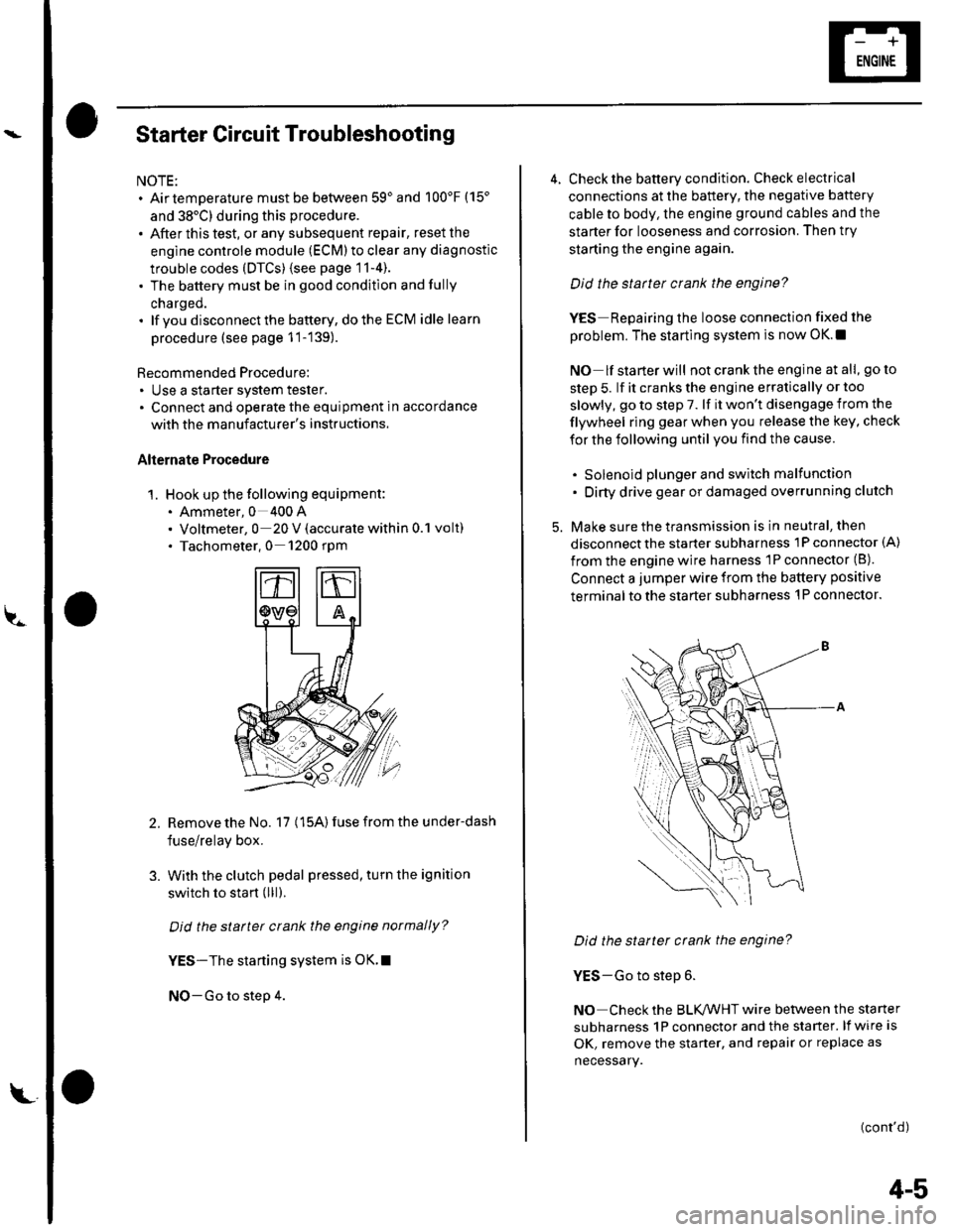
1. Hook up the following equipment:. Ammeter, 0 400 A. Voltmeter, 0 20 V (accurate within 0.1 volt). Tachometer,0 1200 rpm
2.Remove the No. 17 (15A) fuse from the under-dash
fuse/relay box.
With the clutch pedal pressed, turn the ignition
switch to start (lll).
Did the starter crank the engine normally?
YES-The starting system is OK.I
NO-Go to step 4.
3.
L
4-5
4. Check the battery condition. Check electrical
connections at the battery, the negative baftery
cable to body, the engine ground cables and the
starter for looseness and corrosion. Then try
starting the engine again.
Did the statter crank the engine?
YES Repairing the loose connection fixed the
problem. The starting system is now OK.!
NO lf starterwill notcranktheengine atall, goto
step 5. lf it cranks the engine erratically or too
slowly, go to step 7. lf it won't disengage from the
flywheel ring gear when you release the key, check
for the following until you find the cause.
. Solenoid plunger and switch malfunction. Dirty drive gear or damaged overrunning clutch
5. Make sure the transmission is in neutral, then
disconnect the starter subharness 1P connector (A)
from the engine wire harness 'lP connector (B).
Connect a jumper wire from the battery positive
terminal to the starter subharness 'l P connector.
Did the starter crank the engine?
YES-Go to step 6.
NO Check the BLK,ANHT wire between the starter
subharness 1P connector and the starter. lf wire is
OK, remove the starter, and repair or replace as
necessary.
(cont'd)
Page 44 of 1139
Starter Replacement
1. Make sure you have the anti-theft code for the radio.
then write down the frequencies for the radio's
preset buttons.
2. Disconnect the negative cable from the battery first,
then disconnect the positive cable.
3. Disconnect the knock sensor connector.
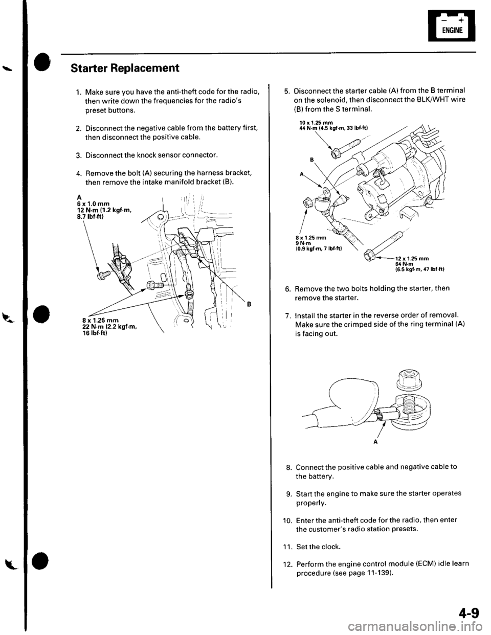
4. Remove the bolt (A) securing the harness bracket,
then remove the intake manifold bracket (B).
A6x1,0mm12 N.m {1.2 kgf.m,8.7 tbt.ft)
8 x 1.25 mm22 N,m 12.2 kgt.m,16 rbf.ftl
L't2.
4-9
5. Disconnect the starter cable (A)from the B terminal
on the solenoid, then disconnect the BLK,/WHT wire
{B) from the S terminal.
10 x 1.25 mm44 N.m {a.5 kgf.m,33lblft)
8 x 1.25 mm9Nm10.9 kgf.m,7 lbl ft)
7.
9.
'10.
11.
2
S'-12x12smm6ilNm{6.5 kgl m,47lbfft)
Remove the two bolts holding the starter, then
remove the starter.
lnstall the starter in the reverse order of removal.
Make sure the crimped side of the ring terminal (A)
is facing out.
Connect the positive cable and negative cable to
the batterY.
Start the engine to make sure the starter operates
propeny.
Enter the anti-theft code for the radio, then enter
the customer's radio station presets.
Set the clock.
Perform the engine control module (EcM) idle learn
procedure (see page 1 '1- 139 ).
I
Page 52 of 1139
lgnition Timing Inspection
1.
4.
5.
Connect the Honda PGM Tester to the data link
connector (DTC), and check for DTC'S. lf a DTC is
present, diagnose and repair the cause before
inspecting the ignition timing.
Startthe engine. Hold the engine at 3,000 rpm with
no load (in Neutral) until the radiator fan comes on,
then let it idle.
Check the idle speed (see page 11-138).
Follow the tester's prompts in the "SCS" menu
{see the tester operator's manual),
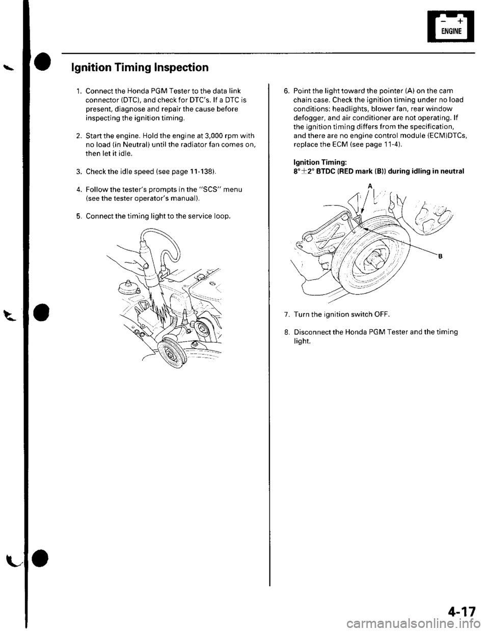
Connect the timing light to the service loop.
o
6. Point the light toward the pointer (A) on the cam
chain case. Check the ignition timing under no load
conditions: headlights, blower fan. rear window
defogger, and air conditioner are not operaling. lf
the ignition timing differs from the specification,
and there are no engine control module {ECM)DTcs,
replace the ECM (see page 11-4)
lgnition Timing:
8"+2" BTDC {RED mark {B)) during idling in neutral
A
7. Turn the ignition switch OFF.
Disconnectthe Honda PGM Tester and thetiming
light.
4-17
Page 59 of 1139
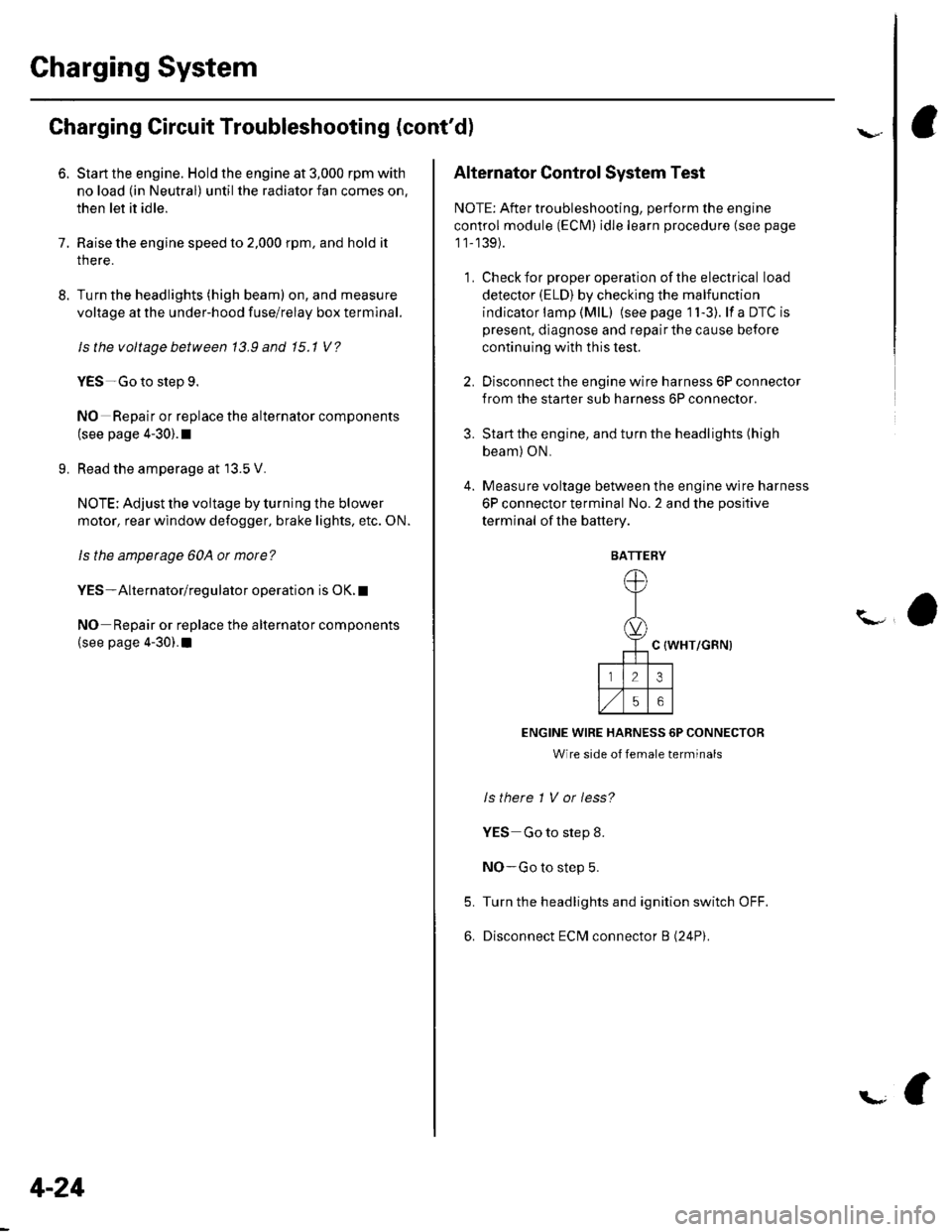
Gharging System
Charging Circuit Troubleshooting (cont'd)
6. Start the engine. Hold the engine at 3,000 rpm with
no load (in Neutral) until the radiator fan comes on,
then let it idle.
7. Raise the engine speed to 2,000 rpm, and hold it
there.
8. Turn the headlights (high beam) on, and measure
voltage at the under-hood fuse/relay box terminal.
ls the voltage between 13.9 and 15.1 v?
YES-Go to step 9.
NO Repair or replace the alternator components
(see page 4-30).1
9. Read the amperage at '13.5 V.
NOTE: Adjust the voltage by turning the blower
motor, rear window defogger, brake lights. etc. ON.
ls the amperage 604 ot morc?
YES-Alternator/regulator operation is OK. I
NO Repair or replace the alternator components(see page 4-30).1
4-24
\,
Alternator Control System Test
NOTE: After troubleshooting, perform the engine
control module (ECM) idle learn procedure (see page
11-139).
1 . Check for proper operation of the electrical load
detector (ELD) by checking the malfunction
indicator lamp (MlL) (see page 1 l-3). lf a DTC is
present, diagnose and repair the cause before
continuing with this test.
2. Disconnect the engine wire harness 6P connector
from the starter sub harness 6P connector.
3. Start the engine, and turn the headlights (high
beam) ON,
4. Measure voltage between the engine wire harness
6P connector terminal No. 2 and the positive
terminal of lhe battery.
C {WHT/GRN)
ENGINE WIRE HARNESS 6P CONNECTOR
Wire side of female terminals
ls there 1 V or less?
YES Go to step 8.
NO-Go to step 5.
Turn the headlights and ignition switch OFF.
Disconnect ECM connector B (24P).
5.
6.
BATTERY
Page 64 of 1139
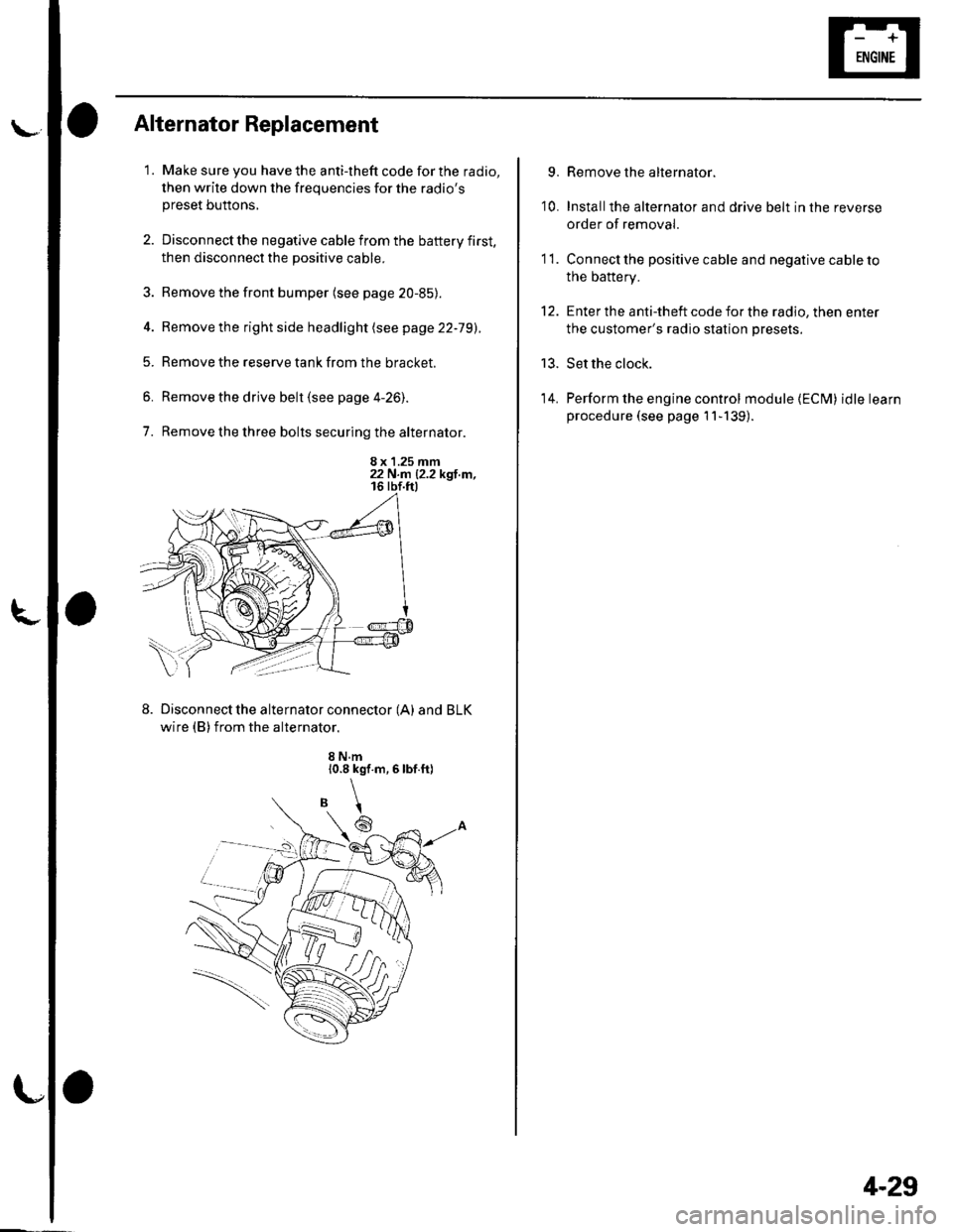
l\-Alternator Replacement
1. Make sure you have the anti-theft code for the radio,
then write down the frequencies for the radio'spreset buttons,
2. Disconnect the negative cable from the battery first,
then disconnect the positive cable.
3. Remove the front bumper (see page 20-85).
4. Remove the right side headlight (see page 22-79).
5. Remove the reserve tank from the bracket.
6. Remove the drive belt (see page 4-26).
7. Remove the three bolts securing the alternator.
8 x 1.25 mm22 N.n 12.2 kgl.m,
Disconnect the alternator connector (A) and BLK
wire (B) from the alternator.
8 N.m10.8 kgf.m,6lbf.ft)
\
6
'I 1.
9.
10.
13.
14.
Remove the alternator.
Installthe alternator and drive belt in the reverse
order of removal.
Connect the positive cable and negative cable to
the battery.
Enter the anti-theft code for the radio, then enter
the customer's radio station presets.
Set the clock.
Perform the engine control module {ECM) idle learn
procedure (see page 11-139).
tt.
4-29
Page 95 of 1139
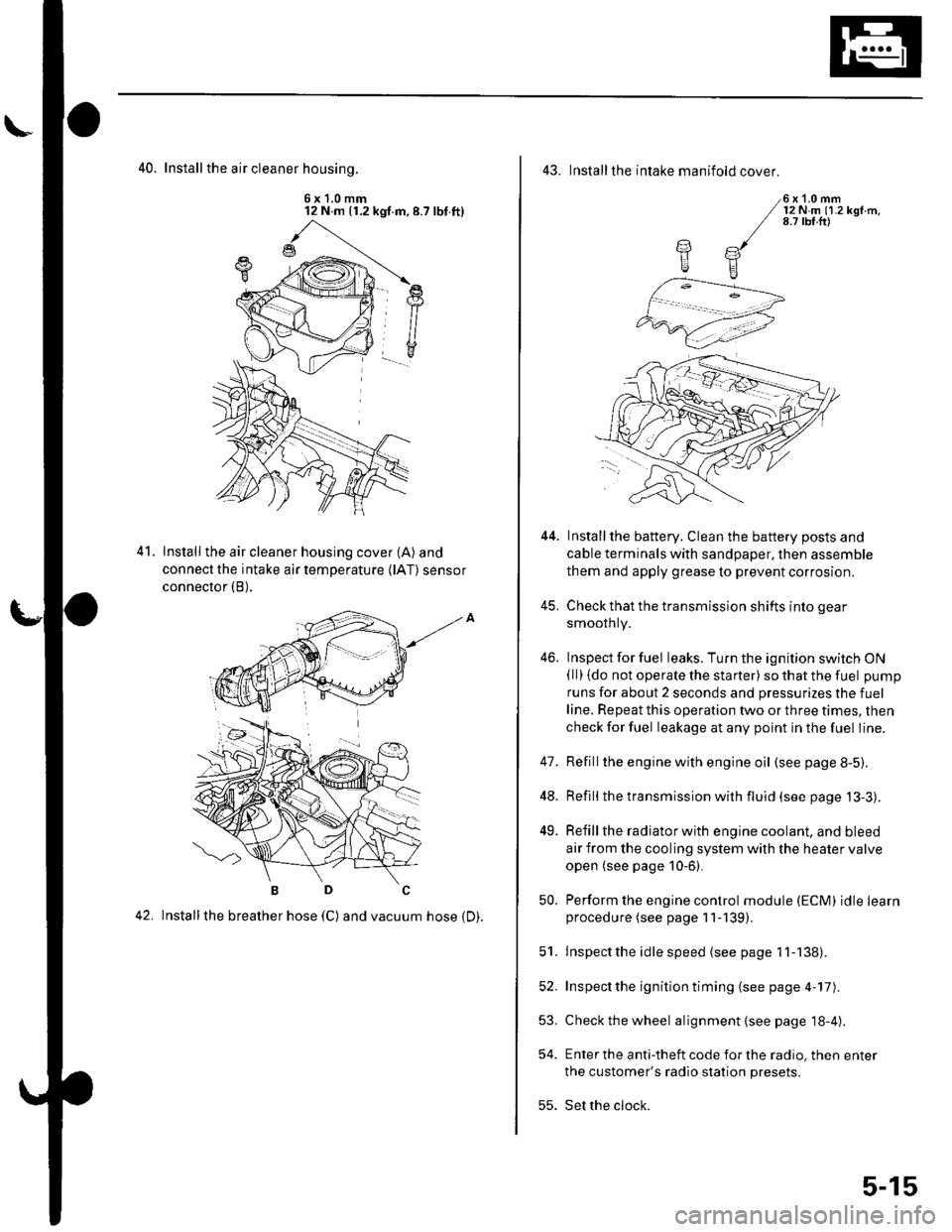
40. Install the air cleaner housinq.
6x1.0mm12 N m (1.2 kgf.m,8.7 lbt.ft)
Install the air cleaner housing cover (A) and
connect the intake air temperature (lAT) sensor
connector (B),
42. Installthe breather hose (C) and vacuum hose 1D).
41.
43. Installthe intake manifold cover.
6x1.0mm12Nm11.2kgf.m.8.7 tbf.ft)
Installthe battery. Clean the battery posts and
cable terminals with sandpaper, then assemble
them and apply grease to prevent corrosion.
Check that the transmission shifts into gear
smoothly.
Inspect for fuel leaks. Turn the ignition switch ON(ll) {do not operate the starter) so that the fuel pump
runs for about 2 seconds and pressurizes the fuel
line. Repeat this operation two or three times, then
check for fuel leakage at any point in the fuel line.
Refillthe engine with engine oil (see page 8-5).
Refill the transmission with fluid (see page 13-3).
Refill the radiator with engine coolant, and bleed
air from the cooling system with the heater valve
open (see page 10-6).
Perform the engine control module (ECM) idle learnprocedure (see page 11-139).
Inspect the idle speed (see page 1 1-138).
Inspect the ignition timing (see page 4-17).
Check the wheel alignment {see page 18-4).
Enter the anti-theft code for the radio, then enter
the customer's radio station presets.
Set the clock.
YE
44.
41.
]tE
46.
48.
49.
52.
53.
54.
50.
51.
55.
5-15
Page 206 of 1139
Fan Controls
Radiator Fan Switch Circuit
Troubleshooting (Openl
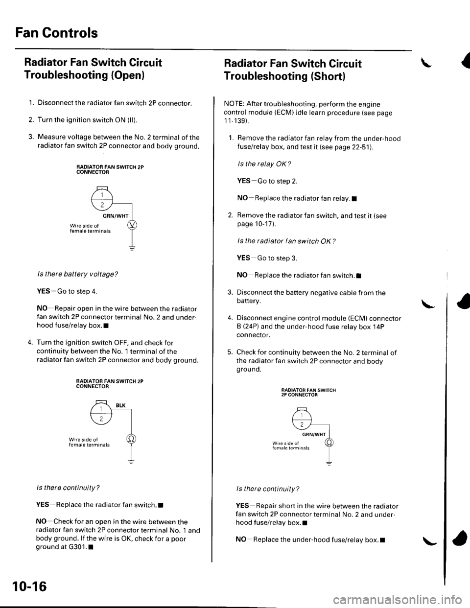
1. Disconnect the radiator fan switch 2P connector.
2. Turn the ignition switch ON (ll).
3. Measure voltage between the No.2 terminal ofthe
radiator fan switch 2P connector and body ground.
RADIATOR FAN SWITCH 2PCONNECTOR
ls there battety voltage?
YES-Go to step 4.
NO- Repair open in the wire between the radiator
fan switch 2P connector terminal No. 2 and under-
hood fuse/relay box.l
Turn the ignition switch OFF, and check for
continuity between the No. '1 terminal of the
radiator fan switch 2P connector and body ground.
RADIATOB FAN SWITCX 2PCONNECTOR
ls there continuity?
YES Replace the radiator fan switch. t
NO Check for an open in the wire between theradiator fan switch 2P connector terminal No. 1 and
body ground. lf the wire is OK, check for a poor
ground at G301.1
10-16
\-
Radiator Fan Switch Circuit
Troubleshooting (Short)
NOTE: After troubleshooting, perform the engine
control module (ECM)idle learn procedure (see page
1 1,139).
1. Remove the radiator fan relay from the under-hood
fuse/relay box, and test it (see page 22-51).
ls the relay OK?
YES Go to step 2.
NO Replace the radiator fan relay.I
2. Remove the radiator fan switch, and test it (see
page 10-17 ).
Is the radiatot tan switch OK?
4.
YES Go to step 3.
NO Replace the radiator fan switch.I
Disconnect the battery negative cable from the
battery.
Disconnect engine control module {ECM) connector
B (24P) and the under hood fuse relay box 14P
connector.
Check for continuity between the No. 2 terminal of
the radiator fan switch 2P connector and bodygrouno.
RADIATOR FAN SWITCH2P CONNECTOR
lstnere continuity?
YES Repair short in the wire between the radiator
fan switch 2P connector terminal No. 2 and under-
hood fuse/relay box.l
NO Replace the under-hood fuse/relay box.t
\I
\
Page 220 of 1139
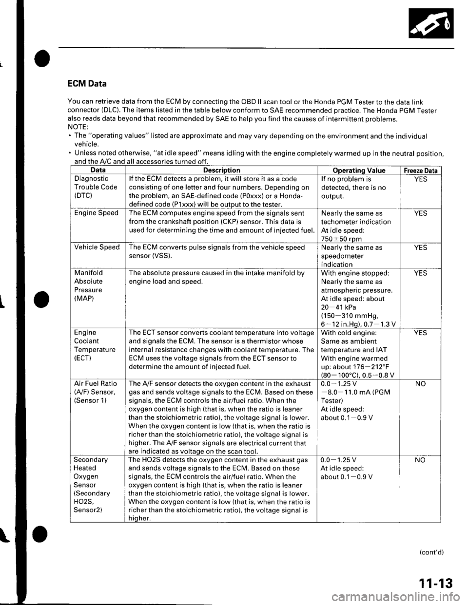
ECM Data
You can retrieve data from the ECI\4 by connecting the OBD ll scan tool or the Honda PGM Tester to the data link
connector (DLC). The items listed in the table below conform to SAE recommended practice. The Honda PGM Tester
also reads data beyond that recommended by SAE to help you find the causes of intermittent problems.
The "operating values" listed are approximate and may vary depending on the environment and the individual
vehicle.
Unless noted otherwise, "at idle speed" means idling with the engine completely warmed up in the neutral position,
and the A,/C and all
Diagnostic
Trouble Code(DTC}
lf the ECM delects a problem, it will store it as a code
consisting of one letter and four numbers. Depending on
the problem, an SAE-defined code (Poxxx) or a Honda,
defined code {P1xxx) will be output to the tester.
The ECI\4 computes engine speed from the signals sent
from the crankshaft position (CKP) sensor. This data is
used for determining the time and amount of injected fuel.
detected, there is no
ourpul.
lf no problem is YES
Nearly the same as
tachometer indication
At idle speed;
The ECM converts pulse signals from the vehicle speed
sensor (VSS).Nearly the same as
speedometer
indication
Manifold
Absolute
Pressure(MAP)
The absolute pressure caused in the intake manifold by
engine load and speed.
With engine stopped: YES
Nearly the same as
almospnenc pressure.
At idle speed: about
20 4'1 kPa(150 310 mmHg,
6- 12 in.Hq).0.7 1.3 V
The ECT sensor converts coolant temperature into voltage
and signals the ECM. The sensor is a thermistor whose
internal resistance changes with coolant tempetature. The
ECM uses the voltage signals from the ECT sensor to
determine the amount of injected fuel.
With cold engine:
Same as ambient
temperature and IAT
With engine warmed
up; about 116 2'12"F
100'c).0.5-0.8 v
Air Fuel Ratio The A,/F sensor detects the oxygen content in the exha ust 0.0 - 1 .25 V(Ay'F) Sensor. gas and sends voltage signals to the Eclvl, Basedonthese 8.0 11.0mA(PGM(Sensor 1) signals, the ECM controls the airlfuel ratio. When the I Tester)
oxygen content is high (that is, when the ratio is leaner At idle speed:
than the stoichiometric ratio), the voltage signal is Iower. about 0.1 0.9 V
When the oxygen content is low (that is, when the ralio is
richer than the stoichiometric ratio). the voltage signal is
higher. The A'lF sensor signals are electrical current that
are indicated as voltaqe on the
The HO2S detects the oxygen content in the exhaust gas
and sends voltage signals to the ECM. Based on these
signals, the ECM controls the airlfuel ratio. When the
oxygen content is high (that is, when the ratio is leaner
than the stoichiometric ratio), the voltage signal is lower.
When the oxygen content is low (that is, when the ratio is
richer than the stoichiometric ratio), the voltage signal is
Secondary
Heated
Oxygen
Sensor(Secondary
H02S,
Sensor2)
0.0 1.25 V NO
At idle speed:
about 0.1 0.9 V
(cont'd)
11-13
Page 221 of 1139
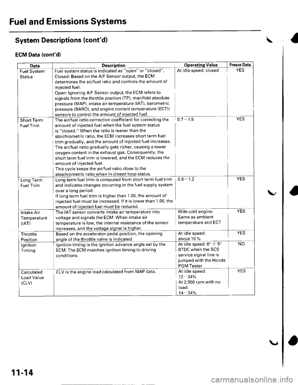
Fuel and Emissions Systems
System Descriptions (cont'd)
ECM Data (cont'd)
w
DataDescriptionOpera'ting ValueFreeze Data
Fuel System
Status
Fuel system status is indicated as "open" or "closed".
Closed: Based on the A,/F Sensor output, the ECM
determines the airlfuel ratio and controls the amount of
injected fuel.
Open: lgnoring Ay'F Sensor output, the ECM refers to
signals from the throttle position {TP), manifold absolute
pressure (MAP), intake air temperature (lAT), barometric
pressure (BARO), and engine coolant temperature (ECT))
sensors to control the amount of iniected fuel.
At idle speed: closedYES
Short Term
FuelTrim
The airlfuel ratio correction coefficient for correcting the
amount of injected fuel when the fuel system status
is "closed." When the ratio is leaner than the
sloichiometric ratio, the ECM increases short term fuel
trim gradually, and the amount of iniected fuel increases.
The airlfuel ratio gradually gets richer, causing a lower
oxygen content in the exhaust gas. Consequently, the
short term fuel trim is lowered, and the ECM reduces the
amount of injected fuel.
This cvcle keeps the airlfuel ratio close to the
stoichiometric ratio when in closed loop status.
o.7 1.5YES
Long Term
Fuel Trim
Long term fuel trim is computed from short term fuel trim
and indicates changes occurring in the fuel supply system
over a long period.
lf long term fuel trlm is higher than 1.00, the amounl of
injected fuel must be increased. lf it is lower than 1.00, the
amount of injected fuel must be reduced.
0.8 1.2YES
Intake Air
Temperature
{IAT)
The IAT sensor converts intake air temperature into
voltage and signals the ECM. When intake air
temperature is low, the internal resistance ofthe sensor
increases, and the voltage signal is higher.
With cold engine:
Same as ambient
temperature and ECT
YES
Throttle
Position
Based on the accelerator pedal position, the opening
anole of the throttle valve is indicated.
At idle speed:
about 10 %
YES
lgnition
Timing
lgnition timing is the ignition advance angle set by the
ECM. The ECM matches ignition timing to driving
conditions.
At idle speed: 8" t 5"
|' tuL wnen rne >L)
service signal line is
jumped with the Honda
PGM Tester
NO
Calculated
Load Value
(cLV)
cLV is the enoine load calculated from IMAP data.At idle speed:
12 34%
At 2.500 rpm with no
toao:'t4- 34%
YES
11-14
\.,
ra