injector voltage HONDA CIVIC 2003 7.G Workshop Manual
[x] Cancel search | Manufacturer: HONDA, Model Year: 2003, Model line: CIVIC, Model: HONDA CIVIC 2003 7.GPages: 1139, PDF Size: 28.19 MB
Page 228 of 1139
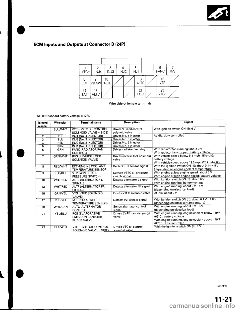
Wire side o{ female terminals
NOTE: Standard baftery voltage is 12 V.
Terminalnumo€tWire color[erminal nameDescriptionSignal
BLUAvHTVTC+ lVTC OIL CONTBOLSOLENOID VALVE +SIDE)Drives VTC oilcontrolWith ignition switch ON (ll): 0 V
2lNJa {No. 4INJECTOR)Driveso. 4 iniectorAt idle: duty controlled
3BLJo.3INJECTORIDriveso.3 iniector4R1)TOR)Driveso.2 iniector
5BRNlNJl 1No. I INJECTOR)Drives No. 1 iniector
6GRNFANC (RAOIATOR FANCONTROL)Drives radiator fan relayWith radiator fan running: about 0 VWith radiator fan stopped: batterv voltaoe
7GRN/vVHTRVS (REVERSE LOCKSOLENOID VALVE)Drives reverse lock solenoidWith vehicle speed below 9.4 mph (15 km/h):battery voltageWith vehicle speed above 12.5 mph (20 km/h): 0 V
8REDAVHTECT (ENGINE COOLANTTFMPFRATURE SENSOR)Detects ECT sensor signalWith the ignition switch ON (ll): about 0.1 4.8 Videoendino on enoine coolant temDerature)
9BLU/BLKVTPSW (VTEC OILPRFSSTIRF SWITCH)Detects VTEc oil pressureswitch sionalWith engine at low engine speed: about 0 .Wirh enoine at hioh enoine soeed: batterv voltaqe
10WHT/BLUALTL (ALTEBNATOR LSIGNAI IDetects alternator L signalWith ignition swit'ch ON (ll): about 0 VWhh enoine runnino: batterv voltaqe
WHT/REDALTF (ALTERNATOR FRSIG NALIDetecls alternator FB signalWith engine running: about 0 V- 5 V{deoendinq on electrical load)
GRN/YELVTS {VTEC SOLENOIDDrives VIEC solenoid valveAt idle: about 0 V
'17REDI/ELIAT (INTAKE AIRTEMPERATURE SENSOR)Detects IAT sensor signalWith ignition switch ON {ll): about 0.1 V 4.8 vl.lcnen.iino on intake air temoerature)
18WHT/GRNALTC (ALTERNATOR
CONTROL)Sends alternator controlWith engine running: about 0 V 5 V(.lcocn.lino on electrical ioad)
21YEUBLUPCS {EVAPORATIVEEMISSION CANISTERPURGE VALVE)
Drives EVAPcanister purgevalveWith engine running, engine coolant below 149'F
165'C): battery voltageWith engine running, engine coolant above 149'F165"C): dutv controlled
23BLK/Vr'HTVTC (VTC OIL CONTROLSOI FNOID VALVE SIDE)Drives VTC oilcontrolWith the ignition switch ON (ll): 0 V
(confd)
11-21
Page 235 of 1139
Fuel and Emissions Systems
(
(
(
System Descriptions (cont'dl
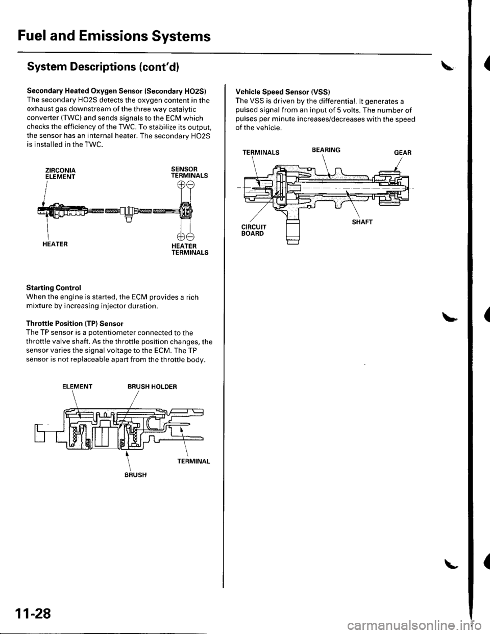
Secondary Heated Oxygen Sensor (Secondary HO2S)
The secondary HO2S detects the oxygen content in the
exhaust gas downstream of the three way catalytic
converter (TWC) and sends signals to the ECM which
checks the efficiency of the TWC. To stabilize its output,
the sensor has an internal heater. The secondarv HO2S
is installed in the TWC.
ztRcoNtaELEMENTSENSORTERMINALS
HEATERTERMINALS
Starting Control
When the engine is started, the ECM provides a rich
mixture by increasing injector duration.
Throttle Position ITP) Sensor
The TP sensor is a potentiometer connected to the
throttle valve shaft. As the throttle position changes, the
sensor varies the signal voltage to the ECM. The TP
sensor is not replaceable apart from the throftle body.
ELEMENTBRUSH HOLDER
gRUSH
11-28
Vehicle Speed Sensor (VSS)
The VSS is driven by the differential. lt generates apulsed signal from an input of 5 volts. The number ofpulses per minute increases/decreases with the speed
of the vehicle.
BEARING
Page 239 of 1139
Fuel and Emissions Systems
(
{
System Descriptions (cont'd)
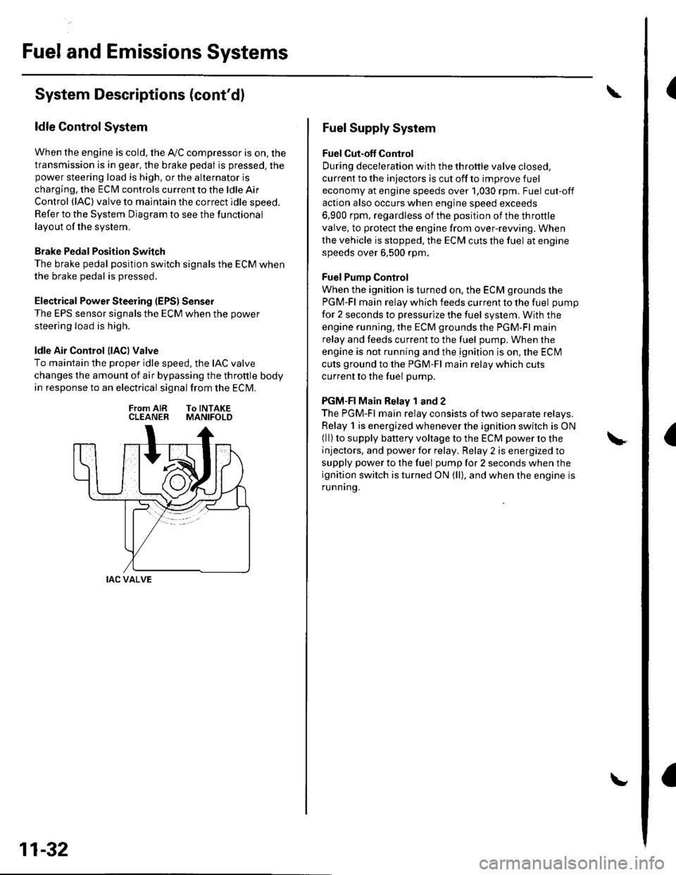
ldle Control System
When the engine is cold, the Ay'C compressor is on, the
transmission is in gear, the brake pedal is pressed. thepower steering load is high, or the alternator is
charging, the ECIM controls current to the ldle Air
Control (lAC) valve to maintain the correct idle speed.
Refer to the System Diagram to see the functional
layout of the system.
Brake Pedal Position Switch
The brake pedal position switch signals the ECM when
the brake pedal is oressed.
Electrical Power Steering (EPS) Senser
The EPS sensor signals the ECM when the power
steering load is high.
ldle Air Control llACl Valve
To maintain the proper idle speed, the IAC valve
changes the amount of air bypassing the throttle body
in response to an electrical signal from the ECM.
From AIR To INTAKECLEANER MANIFOLD
IAC VALVE
11-32
Fuel Supply System
Fuel Cut-off Control
During deceleration with the throttle valve closed,
current to the injectors is cut off to improve fuel
economy at engine speeds over 1,030 rpm. Fuel cut-off
action also occurs when engine speed exceeds
6,900 rpm, regardless of the position of the throttle
valve, to protect the engine from over-rewing. When
the vehicle is stopped. the ECM cuts the fuel at engine
speeds over 6,500 rpm.
Fuel Pump Control
When the ignition is turned on, the ECM grounds the
PGM-Fl main relay which feeds current to the fuel pump
for 2 seconds to pressurize the fuel system, With the
engine running. the ECM grounds the PGM-Fl main
relay and feeds current to the fuel pump. When the
engine is not running and the ignition is on, the ECI\4
cuts ground to the PGM-Fl main relay which cuts
current to the fuel pump.
PGM-FI Main Relay 1 and 2
The PGM-Fl main relay consists of two separate relays.
Relay 1 is energized whenever the ignition switch is ON(ll) to supply battery voltage to the ECM power to the
injectors, and power for relay, Relay 2 is energized to
supply power to the fuel pump for 2 seconds when the
ignition switch is turned ON (ll), and when the engine is
runnrng.
Page 280 of 1139
16.Test-drive the vehicle for several minutes in the
range of the freeze data or under various
conditions if there was no freeze data.
Check for a DTC or a Temporary DTC with the scan
Tool.
ls DTC or Temporary DTC P0301, P0302, P0303
or P0304 indicated?
YES Go to step 18.
NO lntermittent misfire due to bad contact at the
injector connector (no misfire at this time). Make
sure the injector connection is secure. Check for
poor connections or loose terminals at the
injector.l
Determine which cylinder(s) had the misfire.
Does the misf ire occur in the cylinder where the
i njector w as exchanged ?
YES- Replace the faulty injector.I
NO-Go to step 19.
Turn the ignition switch OFF.
Disconnect the ignition coil 3P connector from the
problem cylinder.
Turn the ignition switch ON (ll).
't7 .
18.
19.
20.
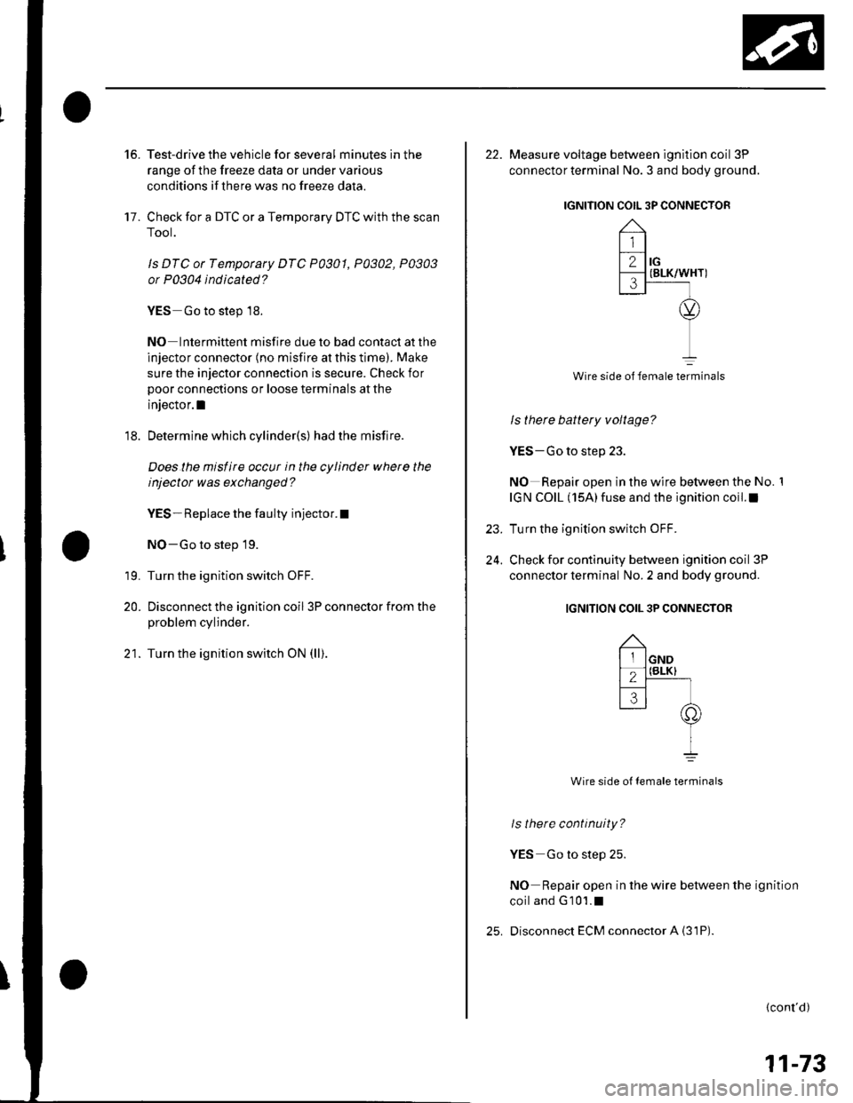
22. Measure voltage between ignition coil 3P
connector terminal No. 3 and body ground.
IGNITION COIL 3P CONNECTOR
Wire side ol female terminals
ls there battery voltage?
YES-Go to step 23.
NO Repair open in the wire between the No. 1
IGN COIL (15A)fuse and the ignition coil.I
Turn the ignition switch OFF.
Check for continuity between ignition coil 3P
connector terminal No. 2 and body ground.
IGNITION COIL 3P CONNECTOR
Wire side ot female terminals
ls there continuity?
YES Go to step 25.
NO Repair open in the wire between the ignition
coiland G101.1
Disconnect ECM connector A {31P)
23.
24.
(cont'd)
11-73
Page 282 of 1139
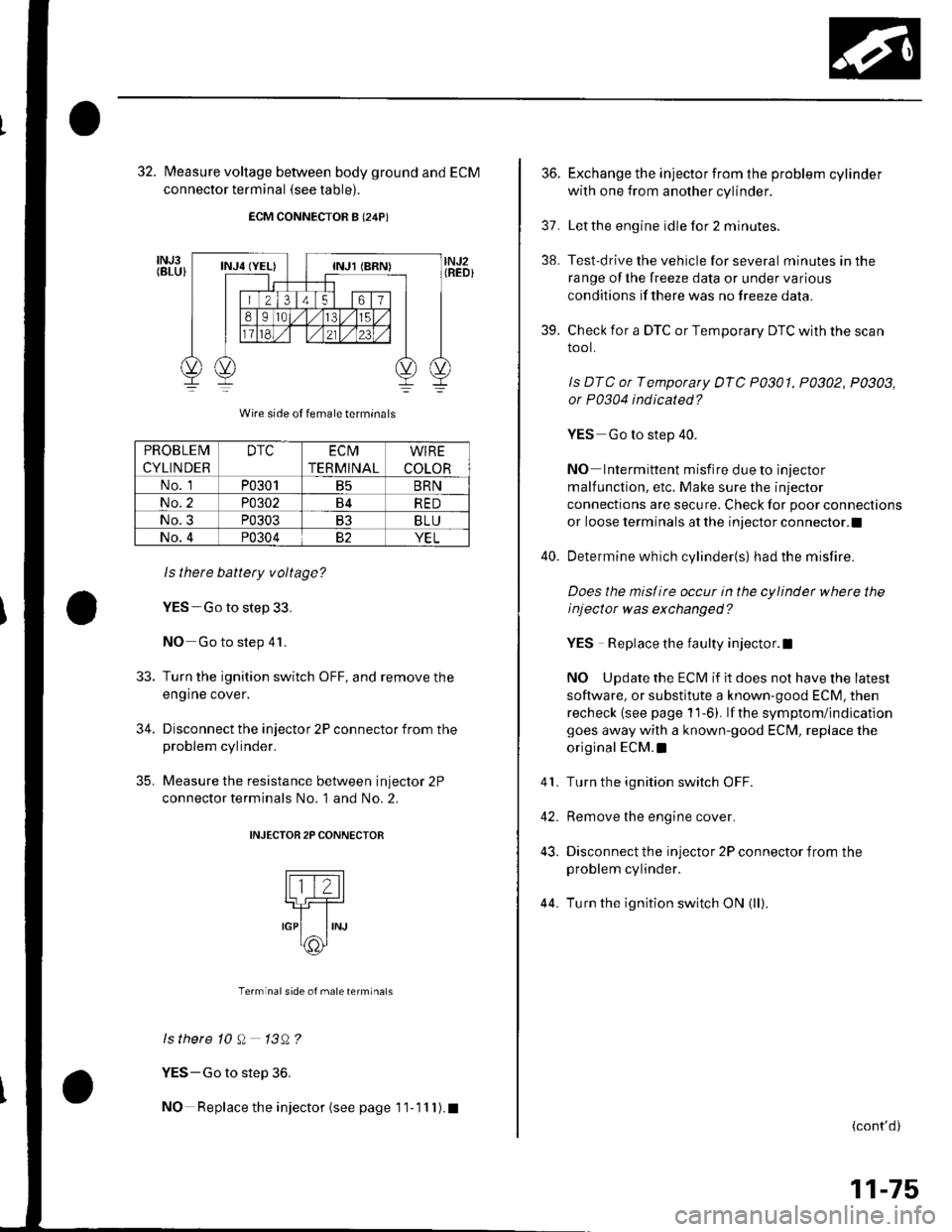
32. fvleasure voltage between body ground and ECM
connector terminal (see table).
ECM CONNECTOR B (24P)
Wire side of female termrnals
ls there battery voltage?
YES-Go to step 33,
NO Go to step 41.
Turn the ignition switch OFF, and remove the
engine cover.
Disconnect the injector 2P connector from theproblem cylinder.
Measure the resistance between injector 2P
connector terminals No. 1 and No. 2.
INJECTOB 2P CONNECTOR
Terminal side of male terminals
ls there 10 Q 13A?
YES-Go to step 36.
NO Replace the injector (see page 1 1- 11 I ). t
33.
34.
35,
PROBLEM
CYLINDER
DTCEC t\4
TERMINAL
WIRE
COLOR
No. 1P0301B5BRN
No.2P0302B4RED
No.3P0303B3BLU
No.4P0304YEL
36.Exchange the injector from the problem cylinder
with one from another cylinder.
Letthe engine idle for 2 minutes.
Test-drive the vehicle for several minutes in the
range oI the lreeze data or under various
condilions if there was no freeze data.
Check for a DTC or Temporary DTC with the scan
tool.
ls DTC or Temporary DTC P0301, P0302, P0303,
or P0304 indicated?
YES Go to step 40.
NO Intermittent misfire due to injector
malfunction, etc. Make sure the injector
connections are secure. Check for poor connections
or loose terminals at the injector connector.l
Determine which cylinder{s} had the misfire.
Does the mislirc occur in the cylinder whete the
i nj ector w as exchanged ?
YES Replace the faulty injector.l
NO Update the ECM if it does not have the latest
software, or substitute a known-good ECM. then
recheck (see page 1 'l-6). lf the symptom/indication
goes away with a known-good EClvl, replace the
original ECM.I
Turn the ignition switch OFF.
Remove the engine cover.
Disconnect the injector 2P connector from the
problem cylinder.
44. Turn the ignition switch ON (ll)
37.
38.
39.
41.
42.
43.
(cont'd)
11-75
Page 283 of 1139
![HONDA CIVIC 2003 7.G Workshop Manual PGM-FI System
a
I
DTC Troubleshooting (contdl
45. Measure voltage between injector 2P connector
terminal No. 1 and body ground.
INJECTOR 2P CONNECTOR
tll-z]
,o, ,"=rrrr*, -lt-
oI
Wire side of female HONDA CIVIC 2003 7.G Workshop Manual PGM-FI System
a
I
DTC Troubleshooting (contdl
45. Measure voltage between injector 2P connector
terminal No. 1 and body ground.
INJECTOR 2P CONNECTOR
tll-z]
,o, ,"=rrrr*, -lt-
oI
Wire side of female](/img/13/5744/w960_5744-282.png)
PGM-FI System
a
I
DTC Troubleshooting (cont'dl
45. Measure voltage between injector 2P connector
terminal No. 1 and body ground.
INJECTOR 2P CONNECTOR
tll-z]
,o, ,"=rrrr*, -lt-
oI
Wire side of female terminals
ls there battery voltage?
YES-Go to step 46.
NO-Repair open in the wire between the injector
and the PGM-Fl main relay l.l
Turn the ignition switch OFF.
Check for continuity between body ground and
ECM connector terminal (see table).
46.
47.
ECM CONNECTOR B {24P)
Wire side of female terminals
ls there continuity?
YES-Repair short in the wire between the ECM
and the ;njector.I
NO-Go to step 48.
PROBLEM
CYLINDER
DTCECM
TERMINAL
WIRE
COLOR
No. 1P030'1B5BRN
No.2P0302B4RED
No.3P0303B3BLU
No. 4P030482YEL
11-76
48. Connect injector 2P co nnector term inal No.2 to
body ground with a jumper wire {see table).
INJECTOR 2P CONNECTOR
Wire side of {emale terminals
49. Check for continuity between body ground and
ECM connector terminal (see table).
ECM CONNECTOR B I24P)
Wire side oJ temale terminals
ls therc continuity?
YES Replace the injector, then recheck.l
NO Repair open in the wire between the ECM and
the injector.I
tll-Z-l-]_r-l_rNJ
IJUMPER
IwrBE
PROBLEM
CYLINDER
DTCWIRE COLOR
No. 1P0301BRN
No.2P0302RED
No. 3P0303BLU
No. 4P0304YEL
PROBLEM
CYLINDER
DTCECM
TERMINAL
WIRE
COLOR
No. 1P0301B5BRN
No. 2P0302B4RED
No. 3P0303B3BLU
No. 4P030482YEL