pcv HONDA CIVIC 2003 7.G Workshop Manual
[x] Cancel search | Manufacturer: HONDA, Model Year: 2003, Model line: CIVIC, Model: HONDA CIVIC 2003 7.GPages: 1139, PDF Size: 28.19 MB
Page 186 of 1139
Intake Manifold and Exhaust System
Intake Manifold Removal and Installation (cont'dl
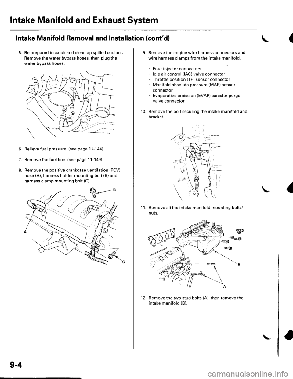
5. Be prepared to catch and clean up spilled coolant.
Remove the water bypass hoses, then plug the
water bypass hoses.
6. Relievefuel pressure (see page 11-'144).
7. Remove the fuel line (seepagell-149).
8. Remove the positive crankcase ventilation (PCV)
hose (A), harness holder mounting bolt (B) and
harness clamp mounting bolt (C).
9-4
\-
(
9.Remove the engine wire harness connectors and
wire harness clamps from the intake manifold.
. Four injector connectors. ldle air control (lAC) valve connector. Throttle position (TP) sensor connector. fvlanifold absolute pressure {lvlAP) sensor
connector. Evaporative emission (EVAP)canister purge
valve connector
Remove the bolt securing the intake manifold and
bracket.
'1 0.
11.Remove allthe intake manifold mounting bolts/
nuts.
Remove the two stud bolts (A), then remove the
intake manifold (B).
1'>
Page 187 of 1139
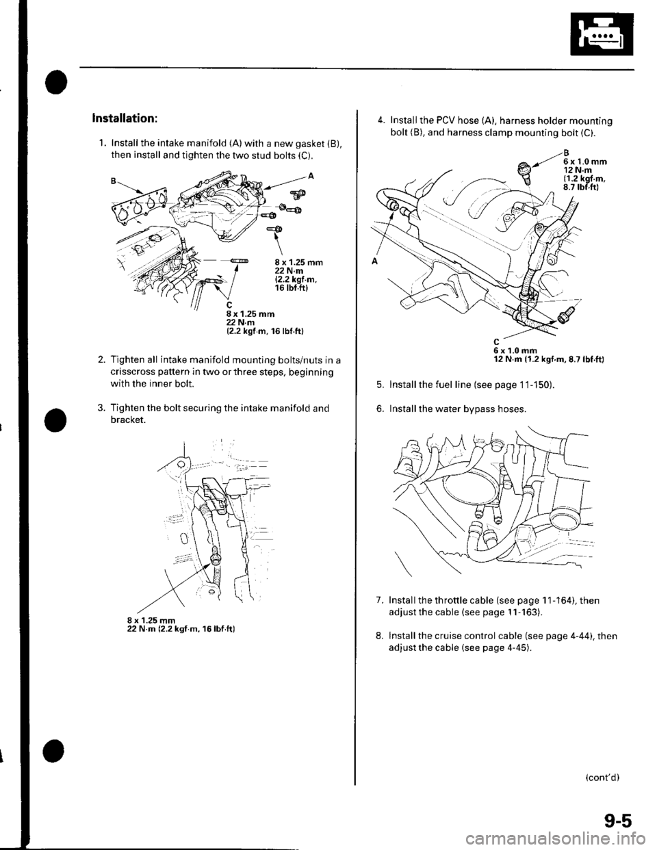
1. Install the intake manifold (A)with a new gasket (B),
then install and tighten the two stud bolts (C).
8 x 1.25 mm22 N.m|.2.2k91.m.16 tbt.ft)
8 x 1.25 mm22 N.rn(2.2 kgf m. 16 lbf.ttl
Tighten all intake manifold mountlng bolts/nuts in a
crisscross pattern in two or three steps, beginning
with the inner bolt.
Tighten the bolt securing the intake manifold and
bracket.
8 x 1.25 mm22 N.m (2.2 ksf m, 16lbf.ft)
*&
\
2.
?
w
4.
7.
5.
6.
Install the PCV hose {A), harness holder mounting
bolt (B), and harness clamp mounting bolt (C).
e-li*h,r
6x1.0mm12 N.m (1.2 kgf.m,8.7 lbf.ft)
Installthe fuel line (see page 11-150).
Installthe water bypass hoses.
Install the th rottle cable (see page 1 1-164), then
adjust the cable (see page 11-163).
Install the cruise control cable (see page 4-44). then
adjust the cable (see page 4-45).
8.
(cont'd)
9-5
Page 208 of 1139
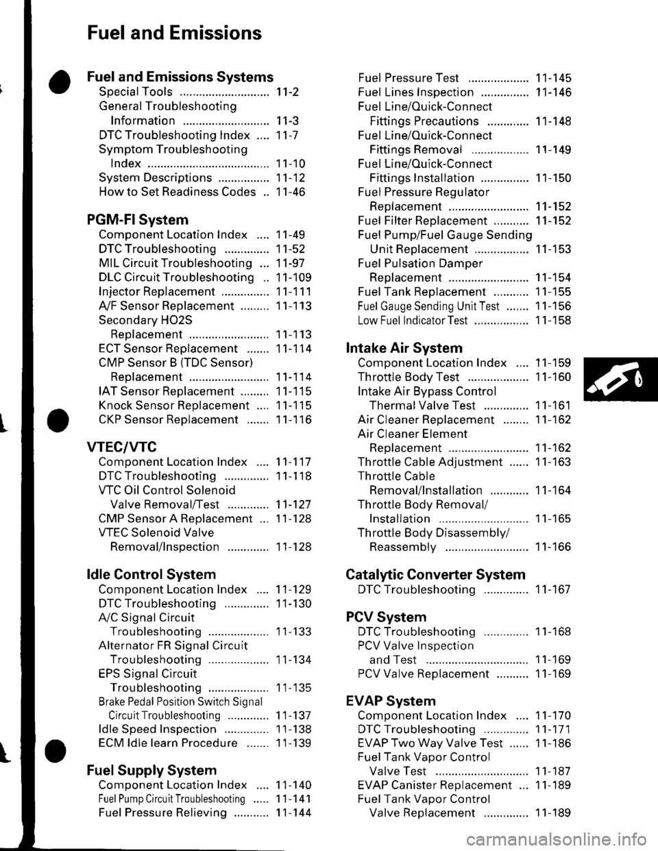
Fuel and Emissions
Fuel and Emissions Systems
SpecialTools
General Troubleshooting
Information
DTC Troubleshooting lndex ....
Symptom Troubleshooting
1ndex...............
System Descriptions ................
Howto Set Readiness Codes ..
PGM-FlSystem
Component Location Index ....
DTC Troubleshooting ..............
MIL Circuit Troubleshooting ...
DLC Circuit Troubleshooting ..
Injector Replacement ...............
A,/F Sensor Replacement .........
Secondary HO2S
Replacement
ECT Sensor Reolacement .......
CMP Sensor B {TDC Sensor)
Replacement
IAT Sensor Replacement .........
Knock Sensor Replacement ....
CKP Sensor Reolacement .......
VTEC/VTC
Comoonent Location Index ....
DTC Troubleshooting ..............
VTC Oil Control Solenoid
Valve Removal/Test .............
CMP Sensor A Replacement ...
VTEC Solenoid Valve
Removal/lnsoection .............
ldle Control System
Component Location Index
DTC Troubleshooting ..............
A,/C Signal Circuit
TroubleshootinS ...................
Alternator FR Signal Circu it
TroubleshootinS ...................
EPS Signal Circuit
TroubleshootinS ...................
Brake Pedal Position Switch Signal
Circuit Troubleshooting .............
ldle Speed Inspection
ECM ldle learn Procedure .......
Fuel Supply System
Component Location Index
Fuel Pump Circuit Troubleshooting
1't-2
I I-J
11-7
1 1-10
11-12
11-46
11-49
11-52
11-97
11-109
11-111
11-113
11-113
11-114
11-114
11-115
11-115
11-116
11-117
1 1-1 18
11-127
11-128
11-128
11-129
1I-130
I t- t55
11-134
1 1- 135
1 1-137
1 1-138
1 1-139
1 1-140
11-141
11-144
Fuel PressureTest ................... 11-145
Fuel Lines Inspection ............... 11-146
Fuel Line/Ouick-Connect
Fittings Precautions ............. 1 1-148
Fuel Line/Ou ick-Con nect
Fittings Removal .................. 1 1-149
Fuel Line/Ou ick-Con nect
Fittings lnstallation ............... 11-150
Fuel Pressure Regu lator
Replacement ......................... 11-152
Fuel Fifter Replacement ........... 11-152
Fuel Pump/Fuel Gauge Sending
UnitReDlacement ................. 11-153
Fuel Pulsation Damoer
Rep1acement ......................... 11-154
Fuel Tank Reolacement ........... 11-155
Fuel GaugeSending UnitTest ....... 11-156
Low Fuel lndicatorTest ................. 1 1-158
Intake Air System
Comoonent Location Index .... 11-159
Throttle BodyTest ................... 11-160
Intake Air Bypass Control
Thermal Valve Test .............. 11-161
Air Cleaner Reolacement ........ 11-162
Air Cleaner Element
Reolacement ......................... 11-162
Throttle Cable Adjustment ...... 11-163
Th rottle Cable
Removal/lnstallation ............ 1 1-164
Th rottle Body Removal/
Installation .. 11-165
Th rottle Body Disassembly/
Reassemblv .......................... 11-166
Catalytic Converter System
DTC Troubleshooting .............. 1 1-167
PCV System
DTC Troubleshooting .............. 1 1-168
PCV Valve InsDection
and Test ...... 1 1- 169
PCV Valve Reolacement .......... 11-169
EVAP System
Component Location Index .... 11-170
DTCTroubleshooting .............. 11-171
EVAP Two Way Valve Test ...... 11-186
Fuel Tank Vaoor Control
Valve Test ... 11-187
EVAP Canister Replacement ... 11-189
Fuel Tank Vaoor Control
Valve Reolacement .............. 1 1-189Fuel Pressu re Relieving ...........
Page 216 of 1139
DTC
{MlL indication*l
Temporary DTCDetection ltemPage
P1259 t22JVTEC System l\4alfunction(see Daqe 11-123)P1291 t20\Electrical Load Detector (ELD) Circuit Low Voltaqe(see Daqe l1-92)P1298 (20)Electrical Load Detector (ELD) Circuit Hiqh Voltaqe(see oaoe 11-93)P1361 (8)Camshaft Position (CMP) Sensor B (Top Dead Center(TDC) Sensor) Intermittent Sional InterruDtion
(see page 11-95)
P1362 (8)Camshaft Position (CMP) Sensor B (Top Dead Center(TDC) Sensor) No Siqnal
(see page 11-95)
P'r456 (90)P1456Evaporative Emissions (EVAP) Control System
Leakaqe (Fuel Tank Svstem)
(see page 11-175)
P14s7 (90)P1457Evaporative Emissions (EVAP) Control System
Leakaqe (EVAP Canister Svstem)
(see page 1'l-180)
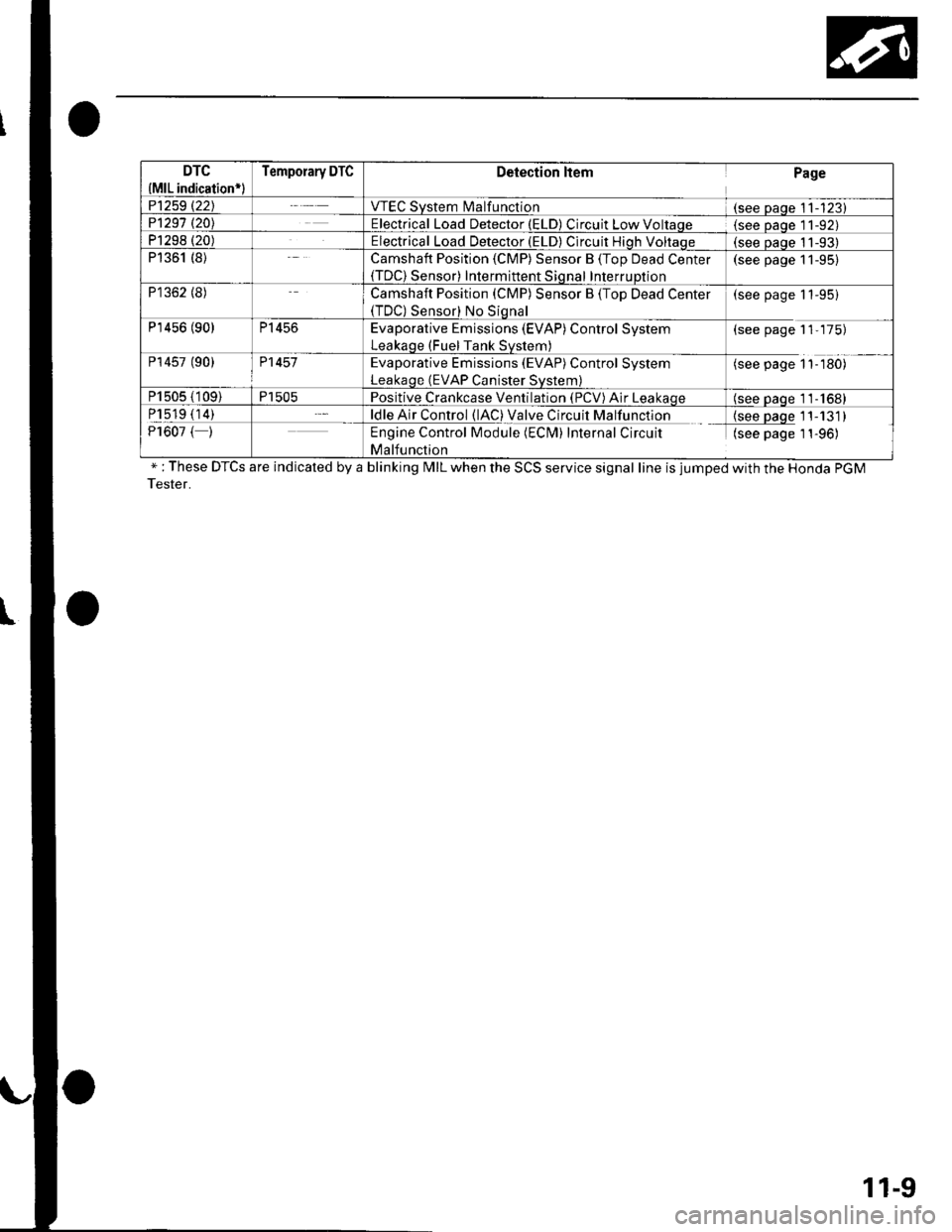
P1505 (109)P1505Positive Crankcase Ventilation (PCV) Air Leakaqe(see oaqe 11-1681
P1519 (14)ldle Air Control (lAC) Valve Circuit Malfunction{see paqe 11-131)P1607 ( )Engine Control Module (ECM) Internal Circuit
Malfunction
(see page 1 1-96)
" : These DTCS are indicated by a blinking MIL when the SCS service signal line is jumped with the Honda PGM
Tester.
11-9
Page 232 of 1139
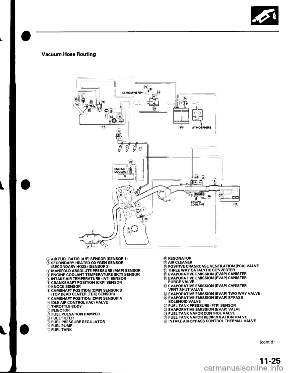
Vacuum Hose Routing
I
O AIR FUEL RATIO IA/F) SENSOR {SENSOR 1}O SECONDARY HEATED OXYGEN SENSORISECONDARY HO2S} {SENSOR 2}
O MANIFOLD ABSOLUTE PRESSURE (MAPI SENSORO ENGINE COOLANT TEMPERATURE {ECT) SENSORO INTAKE AIR TEMPERATURE (IAT) SENSORO CRANKSHAFT POSITION (CKP) SENSORO KNOCK SENSORO CAMSHAFT POSITION (CMPI SENSOR BITOP DEAD CENTER ITDC) SENSOR)
O CAMSHAFT POSITION ICMPI SENSOR A@ IDLE AIR CONTROL (IACI VALVEO THRONLE BODY.O INJECTOR@ FUEL PULSATION OAMPER[I FUEL FILTER@ FUEL PRESSURE REGULATOR@ FUEL PUMP@ FUEL TANK
@ RESONATOR(9 AIR CLEANER@ POSITIVE CRANKCASE VENTILATION {PCVI VALVE@ THREE WAY CATALYTIC CONVERTER@ EVAPORATIVE EMISSION {EVAPI CANISTER@ EVAPORATIVE EMISSION {EVAP) CANISTERPURGE VALVE{} EVAPORATIVE EMISSION (EVAPI CANISTERVENT SHUT VALVE{' EVAPORATIVE EMISSION {EVAP) TWO WAY VALVE@ EVAPORATIVE EMISSION IEVAPI BYPASSSOLENOID VALVE@ FUEL TANK PRESSURE (FTP) SENSOR@ EVAPORATIVE EMISSION IEVAP} VALVE@ FUEL TANK VAPOR CONTROL VALVE60) FUEL TANK VAPOR RECIRCULATION VALVEO INTAKE AIR BYPASS CONTROL THERMAL VALVE
(cont'd)
11-25
Page 241 of 1139
Fuel and Emissions Systems
System Descriptions (cont'dl
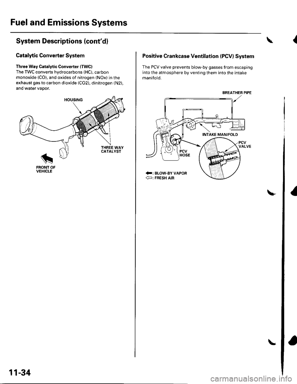
Gatalytic Converter System
Three Way Catalytic Converter (TWC)
The TWC converts hydrocarbons (HC), carbon
monoxide {CO), and oxides of nitrogen (NOx) in the
exhaust gas to carbon dioxide (C02), dinitrogen (N2),
and water vaDor.
THREE WAYCATALYST
FRONT OFVEHICLE
11-34
Positive Crankcase Ventilation (PCVI System
The PCV valve prevents blow-by gasses from escaping
into the atmosphere by venting them into the intake
manifo ld.
:: BLOW-BY VAPOR€: FRESH AIR
\
BREATHER PIPE
{
Page 345 of 1139
ldle Control System
ldle Speed lnspection
NOTE:' Leave the idle air control (lAC) valve connecled.. Before checking the idle speed, check these items:- The malfunction indicator lamp (MlL) has not been
reported on.- lgnition timing- Spark plugs- Air cleaner- PCV system. Pullthe parking brake lever up. Start the engine, and
make sure the headlights are off.
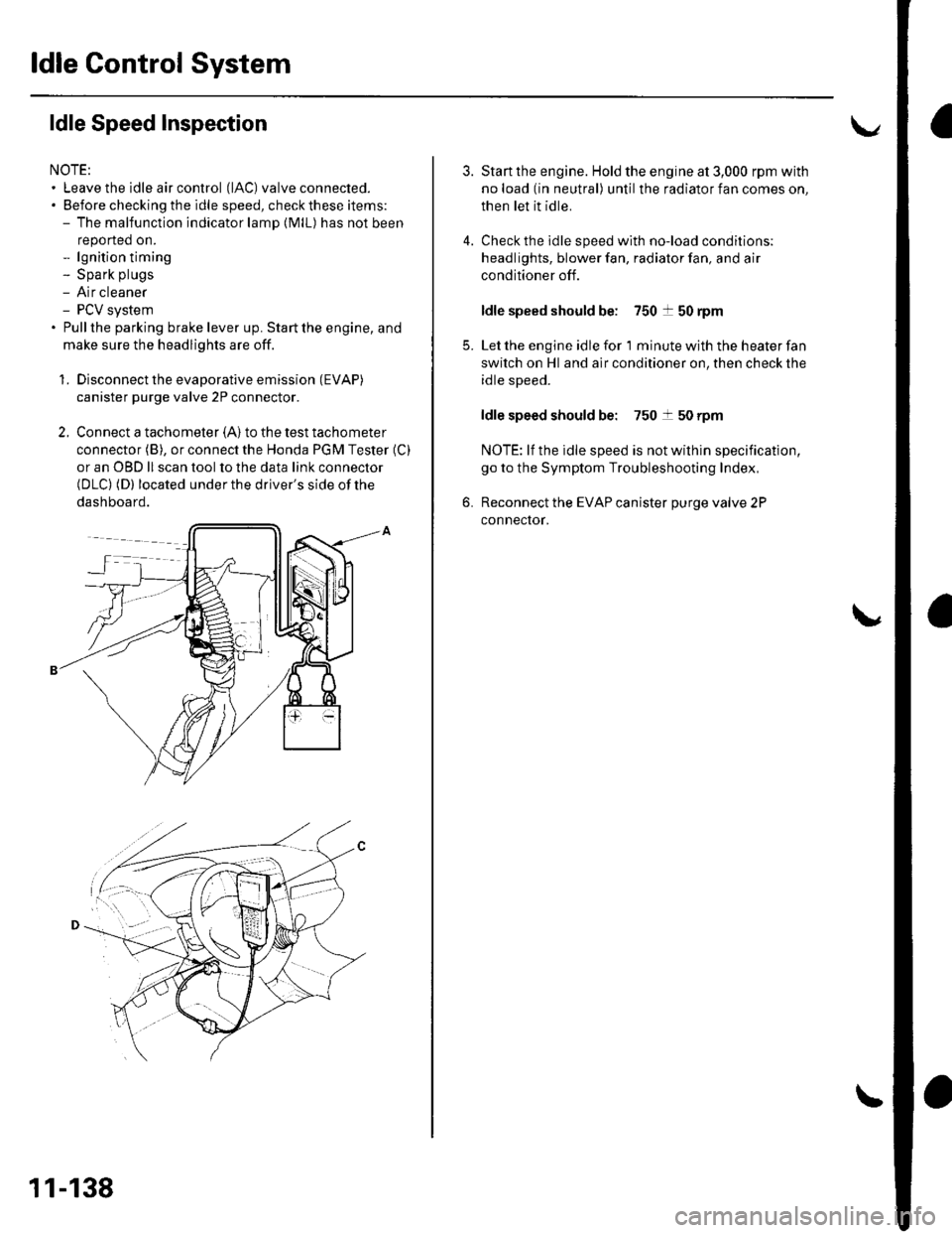
1. Disconnect the evaporative emission (EVAP)
canister purge valve 2P connector.
2. Connect a tachometer (A)to the test tachometer
connector (B), or connect the Honda PGM Tester (C)
or an OBD ll scan tool to the data link connector(DLC) (D) located under the driver's side of the
dashboard.
11-138
4.
3.
5.
6.
Start the engine. Hold the engine at 3,000 rpm with
no load (in neutral) until the radiator fan comes on,
then let it idle.
Check the idle speed with no-load conditions;
headlights, blower fan, radiator fan, and air
conditioner off.
ldle speed should be: 750 t 50 rpm
Let the engine idle for 1 minute with the heater fan
switch on Hl and air conditioner on, then check the
idle speed.
ldle speed should be: 750 t 50 rpm
NOTE: lf the idle speed is not wilhin specification,
go to the Symptom Troubleshooting Index,
Reconnect the EVAP canister purge valve 2P
connector.
Page 369 of 1139
Intake Air System
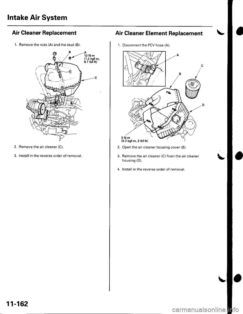
1. Remove the nuts (A) and the stud (B).
Air Cleaner Replacement
Remove the air cleaner (C).
Install in the reverse order of removal.
2.
3.
11-162
Air Cleaner Element Replacement
1. Disconnect the PCV hose 1A).
Open the air cleaner housing cover (B).
Remove the air cleaner (C) from the air cleaner
housing (D).
Install in the reverse order of removal.
2.
3.\,
4.
{0.3 kgf m,2lbf.ft)
Page 375 of 1139
PCV System
DTC Troubleshooting
DTC P1505: PCV Air Leakage
1. Reset the ECM (see page 11-4).
2. Start the engine. Hold the engine at 3,000 rpm with
no load (in neutral) until the radiator fan comes on
3. Let the engine idle tor al least 40 seconds with the
throttle fully closed.
4. Check for a DTC P1505 with the scan tool
ls DTC P1505 indicated?
YES-Check these parts for vacuum leaks l
. PCV valve. PCV hose. EVAP canister purge valve
. Throttle body. Brake booster hose
NO - Intermittent failure, system is OK at this
time.l
11-168
Page 376 of 1139
PCV Valve Inspection and Test
2.
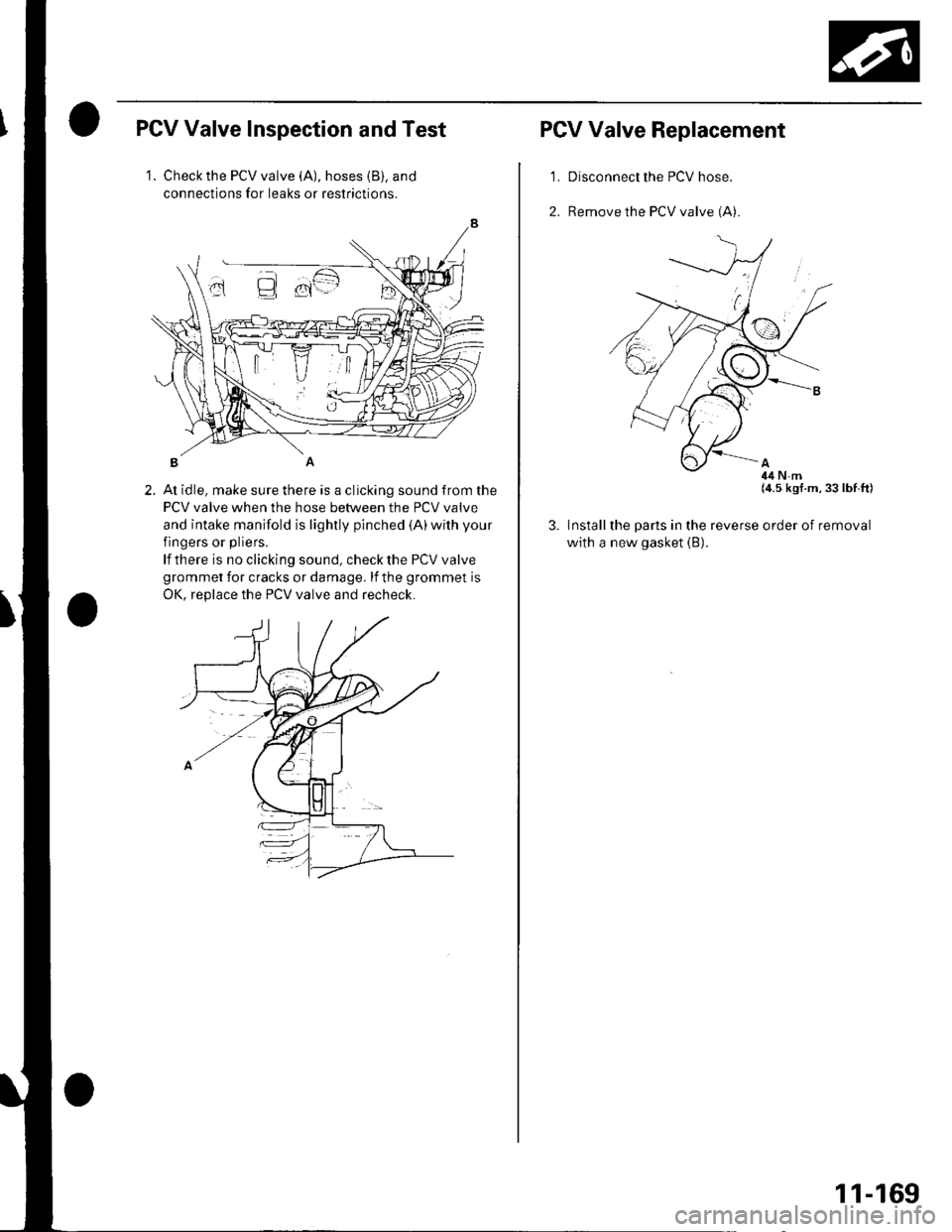
1. Check the PCV valve (A), hoses {B), and
connections for leaks or restrictions.
At idle, make sure there is a clicking sound from the
PCV valve when the hose between the PCV valve
and intake manifold is lightly pinched {A)with your
fingers or pliers.
lf there is no clicking sound, check the PCV valve
grommet for cracks or damage. lf the grommet is
OK. reDlace the PCV valve and recheck.
PCV Valve Replacement
'LDisconnect the PCV hose.
Remove the PCV valve (A).
3. Install
with a
(4.5 kgf.m,33 lbf.ft)
the parts in the reverse order of removal
new gasket (B).
11-169