Wheel replacement HONDA CR-V 1997 RD1-RD3 / 1.G Workshop Manual
[x] Cancel search | Manufacturer: HONDA, Model Year: 1997, Model line: CR-V, Model: HONDA CR-V 1997 RD1-RD3 / 1.GPages: 1395, PDF Size: 35.62 MB
Page 41 of 1395

Lubrication Points
For the details of lubrication points and type of lubricants to be applied. refer to the illustrated index and various work pro-
cedures (such as Assembly/Reassembly, Replacement, Overhaul, Installation, etc.) contained in each section.
Recomm6nded Engine OilEngine oil viscosity for ambient temperature ranges
100'F
-30 -20 .10 0 10 20 30 40'c
r1: Always use Genuine Honda Manual Transmission Fluid {MTF). Using motor oil can cause stiffer shifting because it
does not contain the orooer additives.*2: Always use Genuine Honda Premium Formula Automatic Transmission Fluid (ATF). Using a non-Honda ATF can affect
shift qualitv.+3r Always use Genuine Honda DOT 3 Brake Fluid. Using a non-Honda brake fluid can cause corrosion and decrease the
life of the system.*4: Always use Genuine Honda Power Steering Fluid. Using any other type of power steering fluid or automatic transmis-
sion fluid can caused increased wear and poor steering in cold weather.
API SERVICE LABEL
/,.*-G\
/.'z-\e\t/6AE\ll-;-1 5w-30 /---l
w
API CERTIFICATION SEAL
ffi-20 0 20
NO.LUBRICATION POINTSLUBRICANT
EngineAPI Service Grade: Use SJ "Energy Conserving" grade oil. The oilcontainer may also display the API Certitication seal shownbelow. Make sure it says "For Gasoline Engines." SAE vjscosity:See chart below.
2
TransmissionManualGenuine Honda MTF*1
AutomaticGenuine Honda Premium Formula Automatic Transmission Fluid(ATF)*'
3Rear differentialGenuine Honda CVT Fluid
4Brake line (includes ABS line)Genuine Honda DOT 3 Brake Fluid*3
5Clutch LineBrake fluid DOT 3 or DOT 4*3
6Shift lever pivots (Manual transmission)Grease with molybdenum disultide
1Release fork (Manual transmission)LJrea Grease UM264 P/N 4'1211 - PYs - 305
IPower steering gearboxSteering grease P/N 08733 - B070E
Throttle cable end {Dashboard lower panel holelSilicone grease
10l112
14
Throttle cable end (Throttle link)Brake master cylinder pushrodPedal linkageBattery terminalsFuelfill lidClutch master cylinder pushrod
Multi purpose grease
1617181920
Hood hinges and hood lockTailgate hingesHatch glass hingesDoor hinges, upper and lowerDoor opening detent
Honda White Lithium Grease
21
22
Caliper Piston seal, Dust seal,Caliper pin, PistonShilt cable and select cable {Manual transmission)Silicone grease
23Brake line ioints (Front and rear wheelhouse)Rust preventives
24Power steering systemGenuine Honda Power Steering Fluid-.
25Air conditioning compressorCompressor oil: SP 10 lP/N 38897 - P13 - A0lAH or38899-P13-A01)For Refrigerant: HFC 134a (R,134a)
3-2
www.emanualpro.com
Page 147 of 1395
Engine Block
Speciaf Tools .............7-2
lllustrated lndex ................................... 7-3
Flywheel and Drive Plate
Replacement ..,.,....7-5
Connecting Rod and Grankshaft
End Play .................7-6
Main Bearings
Cfearance ...............7 -7
Selection ................7-8
Connecting Rod Bearings
Clearance ...............7-8
Selection ................7-9
Pistons and Crankshaft
Removal .................7-9
Crankshaft
Inspection .............. 7-11
Pistons
fnspection ..............7-12
fnstaflation .............7-20
Cylinder Block
Inspection ..............7-13
Piston Pins
Removal ..,.......,,..... 7-14
Installation ............. 7-15
Inspection .............. 7-16
Connecting Rods
Selection ................7 -14
Piston Rings
End Gap .................7 -17
Ring-to-Groove Clearance ............... 7 -17
Replacement .........7-18
Alignment .............. 7-18
Crankshaft Oil Seal
lnstallation ............. 7-19
Crankshaft
lnstalfation .............7-20
Oil Seals
fnstalfation ....,..,.....7-23
www.emanualpro.com
Page 151 of 1395
Flywheel and Drive Plate
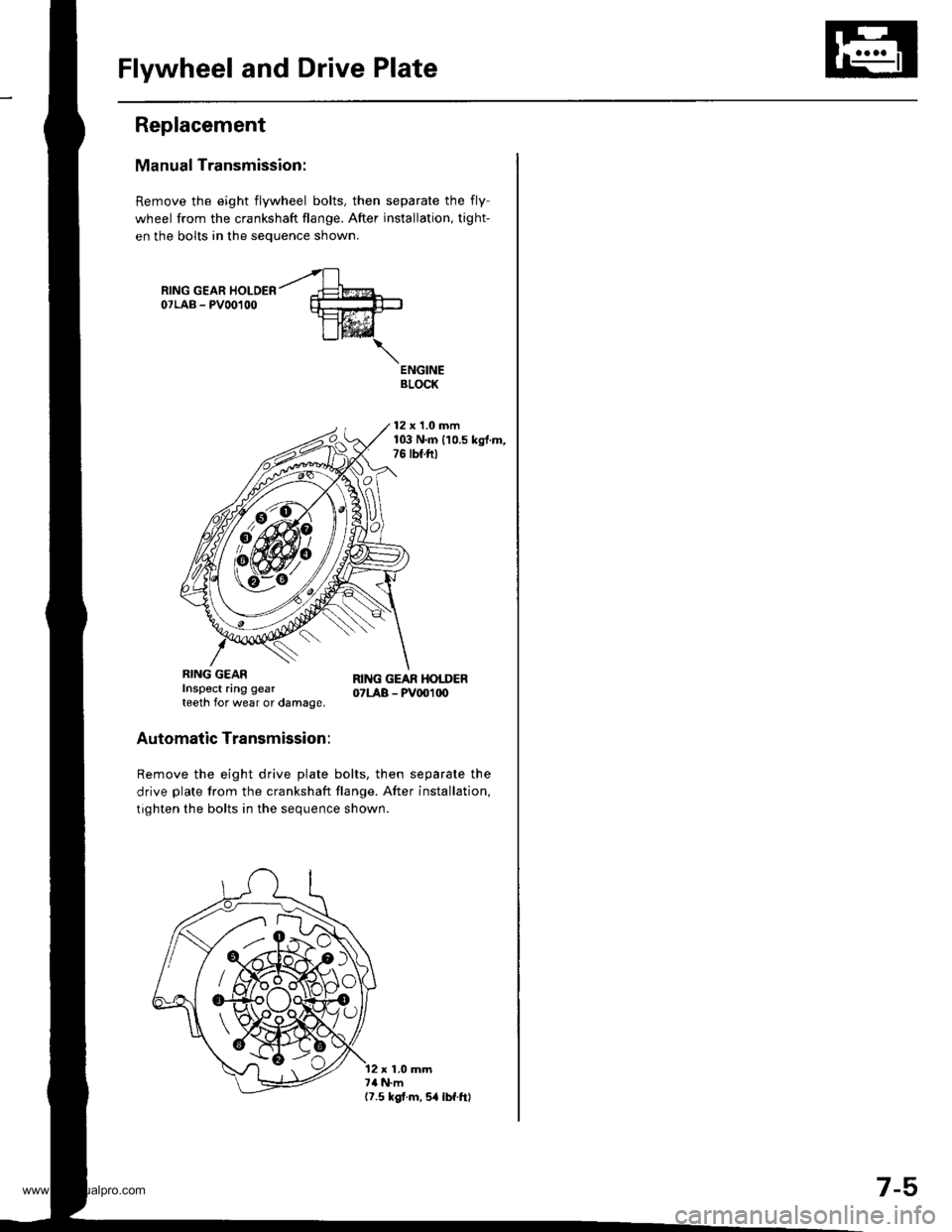
Replacement
Manual Transmission:
Remove the eight flywheel bolts, then separate the fly-
wheel from the crankshaft flange. After installation, tight-
en the bolts in the sequence shown.
ENGINEBLOCK
12 x 1.0 mm103 N.m 110.5 kgf.m,76 lbf.ft)
Automatic Transmission:
Remove the eight drive plate bolts, then separate the
drive plate from the crankshaft flange. After installation,
tighten the bolts in the sequence shown.
RING GEARInspect ring gearteeth for wear or damage,
RI G GEAR HOTDER07LAB - PV001|X)
12 x 1.0 mm7a N.m(7.5 kgt.m,5a lbf.ftl
/ AzXi{'jA\Ao
7-5,
www.emanualpro.com
Page 428 of 1395
Clutch
Speciaf Tools ....,..... ..........' 12-2
lllustrated lndex ........... .'." 12'3
Clutch Pedal
Adjustment ........."."."".12-4
Clutch Master Cylinder
RemovaUlnstallation '." 12'5
Slave Cylinder
Removal/lnstallation .'.. 12-6
Pressure Plate
RemovaUlnspection ..'." 12-7
Clutch Disc
Removal/lnspection ."'.. 12-8
Flywheel
Inspection ...................... 12-9
Replacement ....................................... 1 2-9
Clutch Disc, Pressure Plate
lnstallation ....................' 12-10
Release Bearing
Removal/lnspection ...... 12'11
lnstaflation ..................... 12-12
www.emanualpro.com
Page 436 of 1395
Flywheel
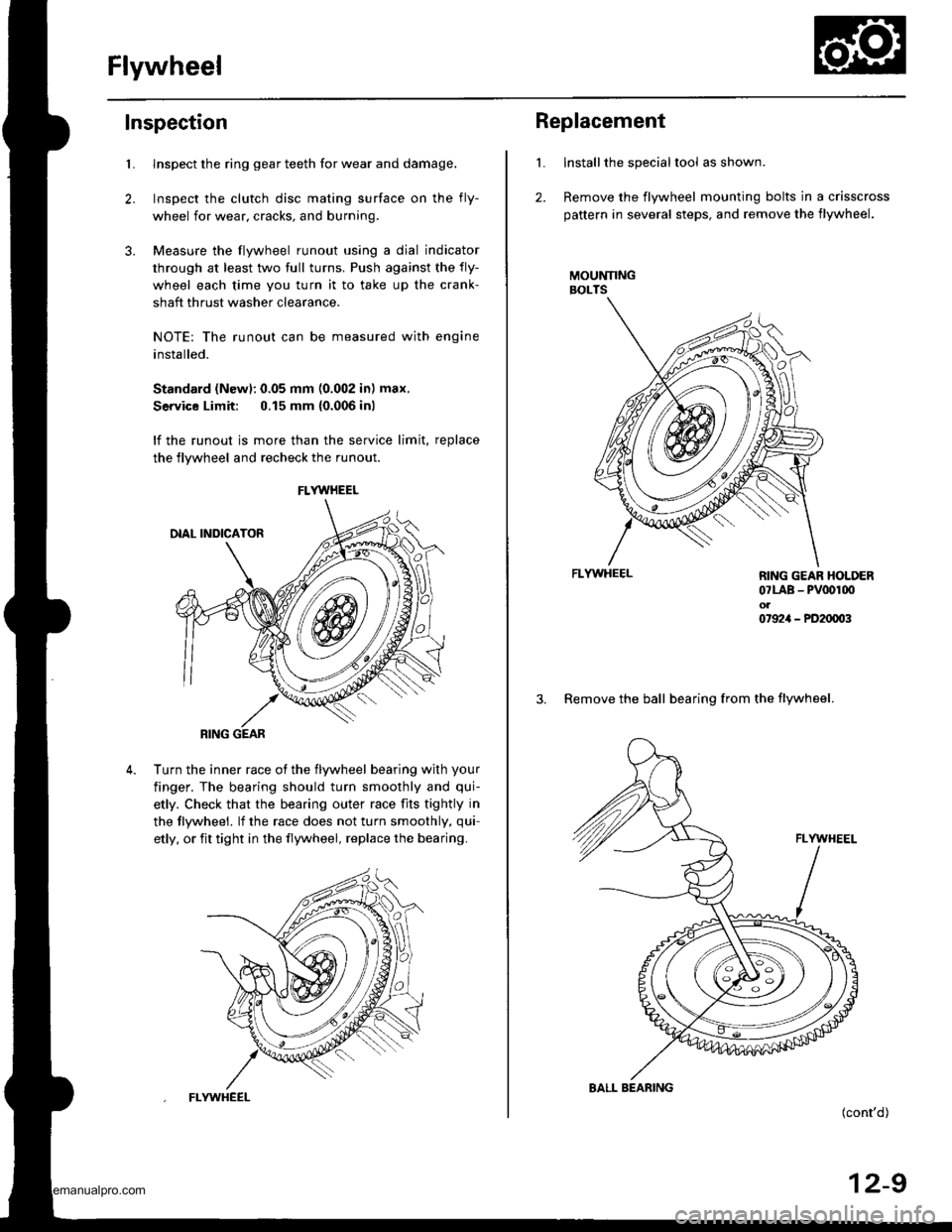
Inspection
2.
3.
Llnspect the ring gear teeth for wear and damage.
Inspect the clutch disc mating surface on the fly-
wheel for wear, cracks, and burning
Measure the flywheel runout using a dial indicator
through at least two full turns. Push against the fly-
wheel each time you turn it to take up the crank-
shaft thrust washer clearance.
NOTE: The runout can be measured with engine
installed.
Standard (Newl: 0.05 mm (0.002 in) max.
Service Limit: 0.15 mm {0.006 inl
lf the runout is more than the service limit, replace
the flywheel and recheck the runout
Turn the inner race ot the flywheel bearing with your
finger. The bearing should turn smoothly and qui-
etly. Check that the bearing outer race fits tightly in
the tlywheel. lf the race does not turn smoothly, qui-
etly, or fit tight in the flywheel, replace the bearing.
FLYWHEEL
RING GEAR
FLYWHEEL
L
2.
Replacement
Installthe special tool as shown.
Remove the flywheel mounting bolts in a crisscross
pattern in several steps, and remove the flywheel.
MOUNNNGBOLTS
FLYWHEEL
(cont'd)
12-9
RING GEAR HOLDER07LAB - PV00r00ol07924 - PD20003
3. Remove the ball bearing from the flywheel.
BALL BEARING
www.emanualpro.com
Page 437 of 1395
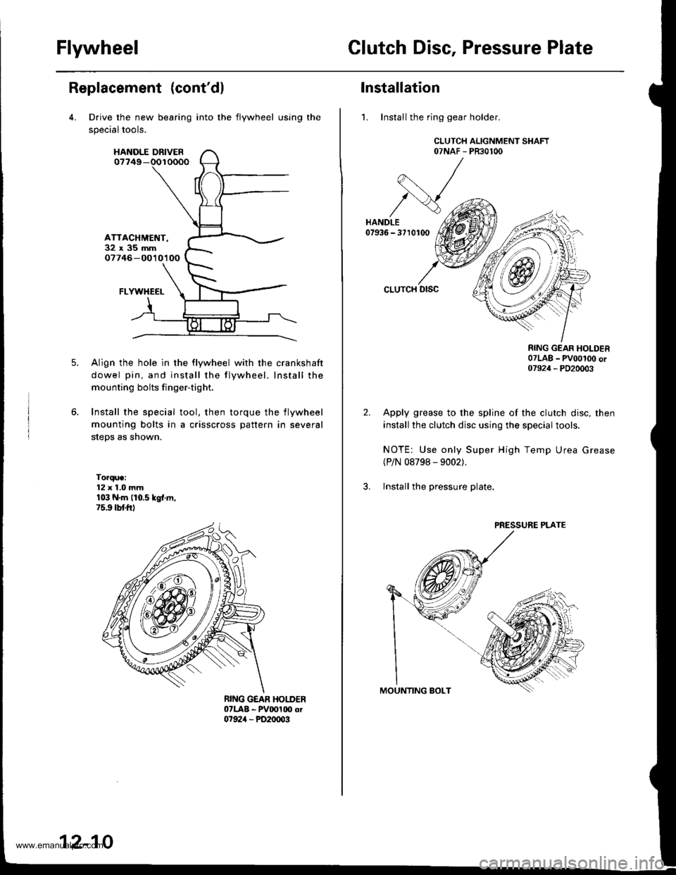
FlywheelClutch Disc, Pressure Plate
Replacement (cont'dl
Drive the new bearing
specialtools.
HANOLE DRIVER07749-
ATTACHMET{T-32x35mm07746 -O010100
FLYWHECI-
Align the hole in the flywheel with the crankshaft
dowel pin, and install the flywheel. Install the
mounting bolts finger-tight.
Install the special tool, then torque the flywheel
mounting bolts in a crisscross pattern in several
steps as shown.
Torque:12 x 1.0 mmr03 N.m (10.5 kgl.ln,75.9 tbtftl
into the flywheel using the
12-10
Installation
1. Install the ring gear holder.
CLUTCH ALIGNMENT SHAFT07NAF - PR30100
CLUTCH DISC
RING GEAR HOLDER07LAB _ pvoot(x) or07924 _ PD20003
Apply grease to the spline of the clutch disc, then
install the clutch disc using the special tools.
NOTE: Use only Super High Temp Urea Grease(P/N 08798 - 9002).
lnstall the pressure plate.
PRESSURE PLATE
www.emanualpro.com
Page 443 of 1395
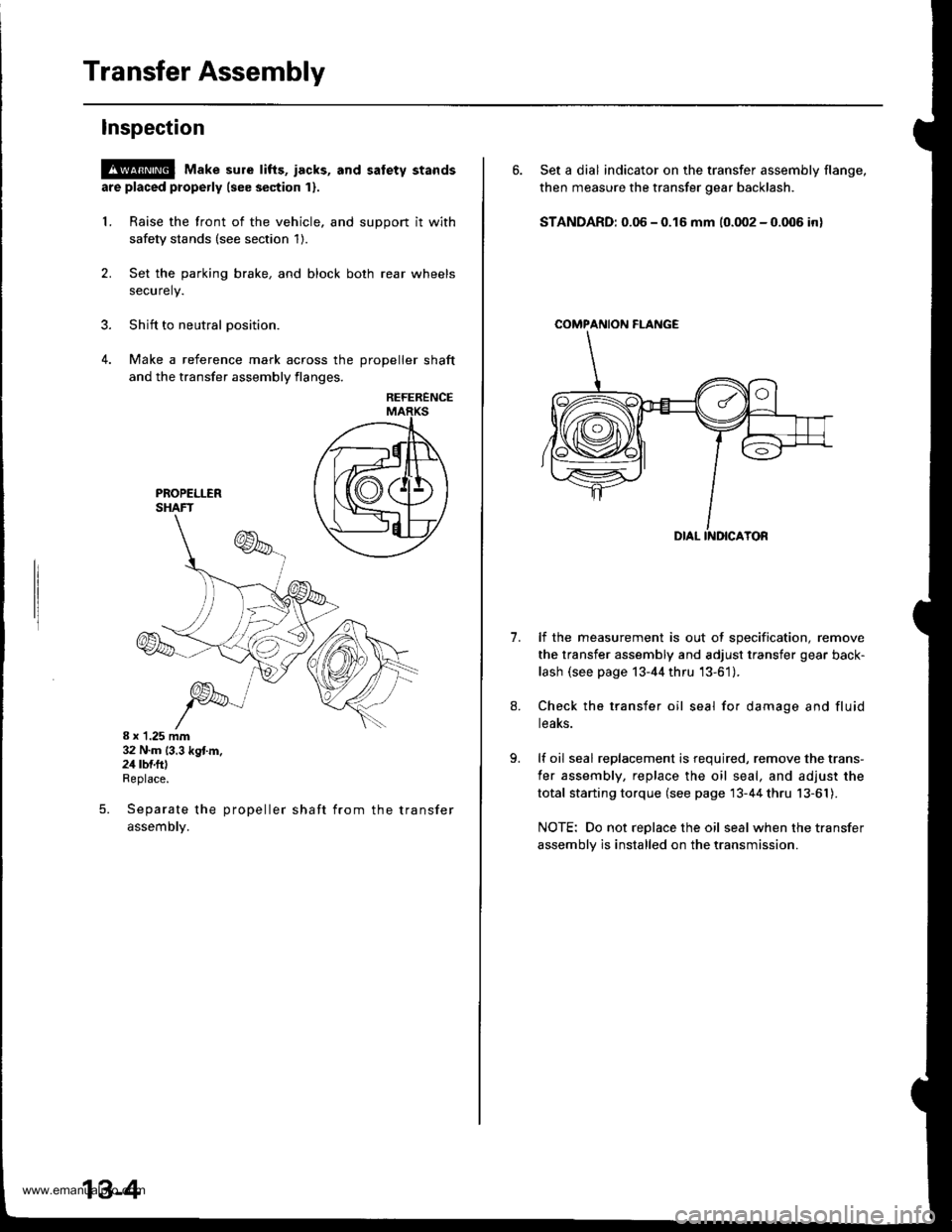
Transfer Assembly
lnspection
@ Make sure tifts, iacks, and satety stands
are placed properly (see section 1).
L Raise the front of the vehicle, and support it with
safety stands (see section 1).
2. Set the parking brake, and block both rear wheels
securely.
3. Shift to neutral oosition.
4. Make a reference mark across the DroDeller shaft
and the transfer assembly flanges,
REFERENCE
8 x 1.25 mm32 N.m (3.3 kg{.m.24 rbf.ftlReplace.
Separate the propeller shaft from the transfer
assemDty.
5.
13-4
6. Set a dial indicator on the transfer assembly flange,
then measure the transfer gear backlash.
STANDARD: 0.06 - 0.16 mm (0.002 - 0.006 in)
COMPAf{ION FI-ANGE
1.lf the measurement is out of specification, remove
the transfer assembly and adjust transfer gear back-
lash (see page 13-44 thru '13-61).
Check the transfer oil seal for damage and fluid
teaKs.
lf oil seal replacement is required, remove the trans-
fer assembly, replace the oil seal, and adjust the
total starting torque (see page 13-44 thru 13-61).
NOTE: Do not replace the oil seal when the transfer
assembly is installed on the transmission.
www.emanualpro.com
Page 656 of 1395
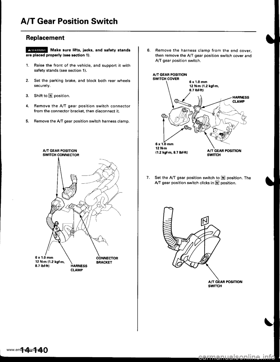
A/T Gear Position Switch
Replacement
@ Make 3ure lifts, iacks, and safety stands
ar€ placod properly lsoo soction 1).
1. Raise the front of the vehicle, and support it with
safety stands (see section 1).
2. Set the parking brake, and block both rear wheels
securely.
3. Shift to E position.
Remove the A/T gear position switch connector
from the connector bracket, then disconnect it.
Remove the AfI gear position switch harness clamp.
5x1.0mm12Nm11.2kgf.m,8.7 tbf.fttBRACIGT
14-140
6. Remove the harness clamp from the end cover,
then remove the Aff gear position switch cover and
Ay'T gear position switch.
A/T GEAF POSITIONswrTcH covER6x1.0mm12 N.m 11.2 kgt m.8.7 lbf.ftl
1.Set the IVT gear position switch to E position. The
AfI gear position switch clicks in E position.
POSmON
6x1.0mm12 N.m
{1.2 kg{.m,8.7 lbtftl
swlTcH
www.emanualpro.com
Page 680 of 1395
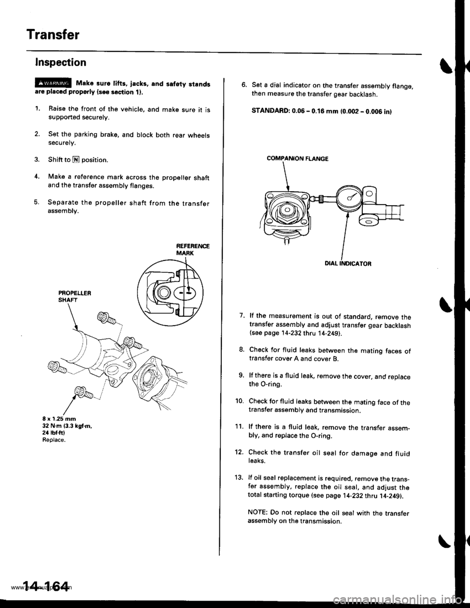
Transfer
4.
Inspection
@E Mako suro lifts, jacks, and safety standsare placod properly lsoe section t).
1. Raise the front of the vehicle, and make sure it issupported securely.
2. Set the parking brake, and block both rear wheelssecurely.
Shift to E position.
Make a reference mark across the propeller shaftand the transfer assembly flanges.
Separate the propeller shaft from the transferassembly.
8 x 1.25 mm32 N.m 13.3 kgl,m,24 lbf.ftlReplace.
14-164
\
6. Set a dial indicator on the transfer assembly flange.then measure the transfer gear backlash.
STANDARD: 0.06 - 0.16 mm (0.002 - 0.006 inl
7. lf the measurement is out of standard, remove thetransfer assembly and adjust transfer gear backlash{see page '14-232 thru 14-2491.
8. Check for fluid leaks between the mating faces oftransfer cover A and cover B.
9. lf there is a fluid leak, remove the cover, and reDlacethe O-ring.
'10. Check for fluid leaks between the mating face of thetransfer assembly and transmission.
11. lf there is a fluid l€ak, remove the transf€r assem-bly, and replace the O-ring,
12. Check the transfer oil seal for damage and fluidle8ks.
13, lf oil seal replacement is required. remove the trans-fer assembly, replace the oil seal, and adjust thetotal starting torque (see page 1+232 thtu ]'4-249||.
NOTE: Do not replace the oil seal with the transferassembly on the transmission.
COMPANION FLANGE
www.emanualpro.com
Page 846 of 1395

Steering
Special Toofs ............. 17-2
Component Locations
Index ................ ....... 17-3
Troubleshooting
General Troubleshooting ................ 1 7-4
Noise and Vibration ......................... 17-8
Fluid Leaks ............. 17-10
Inspection and Adiustment
Steering Operation .......................... 17-12
Power Assist Check
With Vehicle Parked ....................
Steering Linkage and Gearbox .......
Pump Belt
Rack Guide Adjustment ...................
Fluid Rep|acement ...................,,.,....
Pump Pressure Check .................,,...
*Steering Wheel
Removal ................. 17-18
*Steering Column
Removal/lnstallation ................ ....... 17 -2O
lnspection .............. 17-21
Steering Lock Replacement ............ 17 -22
Power Steering Hoses, Lines
Ffuid Leakage Inspection ................. 17 -23
Repfacement .......... 17-23
Power Steering Pump
Repfacement .......... 17-24
Disassembly ...........17-25
fnspection .............. 17-26
Reassembly ............ 17-28
Power Steering Gearbox
Removal ................. 17-31
Disassembly ........... 17-34
Reassembly ............ 17-40
Ball Joint Boot Replacement .......... 17-50
Installation ............. 17-51
17-12
17-13
17-14
l7-15
17-15
17-16
Disassembly/Reassembly............... 17-18
4'%/b.......... -r'-7--a/
SUPPLEN\EN AL RES\RA(N SYSTES{ (SRS\
This model has an SRS which includes a driver's airbag in the steering wheel hub. a passenger's airbag in the dashboardabove the glove box ('97 - 00 models), and seat belt tensioners in the seat belt retractors ('98 - 00 models). Informationnecessary to safely service the SRS is included in this Service Manual. ltems marked with an asterisk (*) on the contentspage include, or are located near, SBS components. Servicing. disassembling or replacing these items will require specialprecautions and tools, and should only be done by an authorized Honda oearer.
To avoid rendering the SRS inoperative, which could lead to peFonal iniury or death in the event of a sevore trontalcollision. allSRS service work must be performod by an authorized Honda dealer.lmproper service procedurgs, including incorrect removal and installalion of the SRS, could lead to personal iniurycaused by unintontional deployment of th€ airbags {'97 - 00 models), and seat belt tensioners ('98 - 00 modelsl.Do not bump the SRS unit. Otherwise, the system may lail in case ot a collision, or the airbags may deploy when theignition switch is ON (lll.
SRS electrical wiring harnesses are identitied by yellow colof coding. Ralated components are located in the steeringcolumn, front console, dashboard, dashboard lower panel, and in the dashboard above the glove box. Do not use elec-trical test equipment on these cilcuits,
www.emanualpro.com