Wheel replacement HONDA CR-V 1997 RD1-RD3 / 1.G Owner's Manual
[x] Cancel search | Manufacturer: HONDA, Model Year: 1997, Model line: CR-V, Model: HONDA CR-V 1997 RD1-RD3 / 1.GPages: 1395, PDF Size: 35.62 MB
Page 914 of 1395
Front SuspensionFront Damper
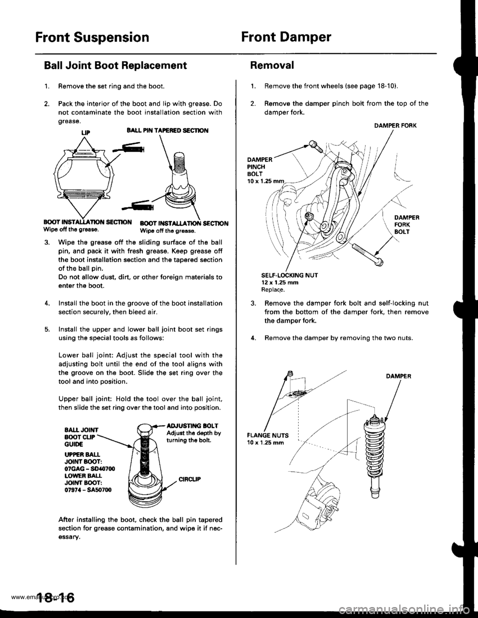
Ball Joint Boot Replacement
1.
BALL PIT{ TAPEFEO S€CTION
B{rcY HSISECTIO BOOT |NSTSECTIONwip6 off tho gr6aso.Wipo otf th6 grors€.
Wipe the grease off the sliding surface of the ball
pin, and pack it with fresh greass. Keep grease off
the boot installation section and the taoered section
of the ball pin.
Do not allow dust, dirt, or other foreign materials to
enter the boot.
Install the boot in the groove of the boot installation
section securelv, then bleed air.
Install the upper and lower ball joint boot set rings
using the special tools as follows:
Lower ball joint: Adjust the special tool with the
adjusting bolt until the end of the tool aligns with
the groove on the boot. Slide the set ring over the
tool and into oosition.
Upper ball joint: Hold the tool over the ball joint,
then slide the set ring over the tool and into position.
EAII JOINTAD'USN G BOLTAdjust th6 depth byturning the bolt.
Remove the set ring and the boot.
Pack the interior of the boot and lip with grease. Do
not contaminate the boot installation section with
grease.
B(X)T CUPGUttrE
UPPER BAI.IJott'tr Boor:07GAG - SO407q)LOWEF BATIJOIIYI EOOTI0t97il - SA507lXl
After installing the boot, check the ball pin tapered
section for grease contamination, and wipe it if nec-gssary.
18-16
Removal
1, Remove the front wheels (see page 18-10).
2. Remove the damper pinch bolt from the top of the
damper fork.
DAMPERPINCHBOLT'10 x 1.25
SELF.LOCKING NUT12x 1.25 fifiReplace.
Remove the damper fork bolt and self-locking nut
from the bottom of the damper fork, then remove
the damper fork.
Remove the damper by removing the two nuts.
DAMPER
DAMPER FORK
www.emanualpro.com
Page 917 of 1395
Rear Suspension
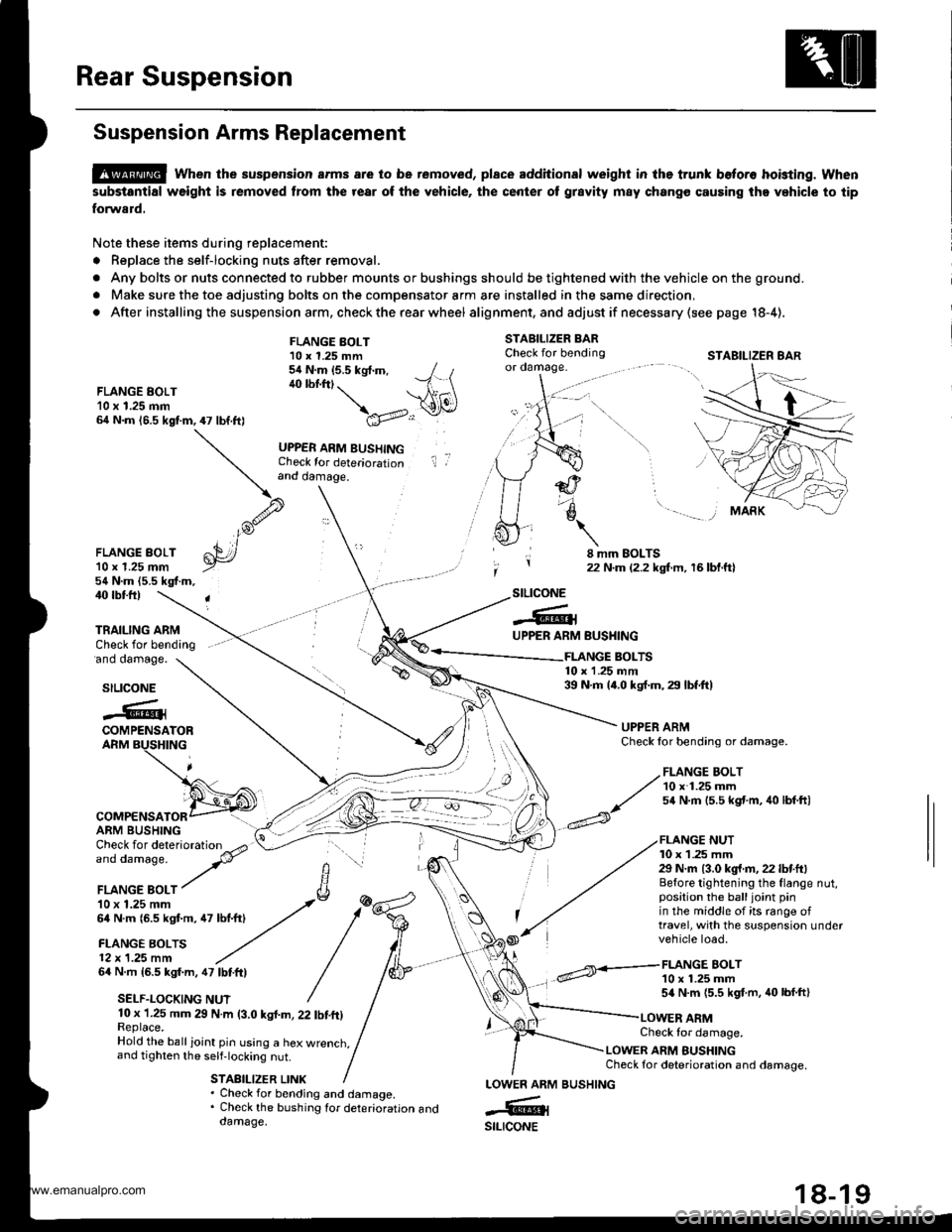
Suspension Arms Replacement
@ when the suspension arms are to be removed, plsce additional weight in lhe trunk beto.o hoisting. when
substantial weight is removed from the rear of the vehicle, the center ot grsvity m8y chango causing the vehicle to tip
forward.
Note these items during replacement:
. Replace the self-locking nuts after removal.
. Any bolts or nuts connected to rubber mounts or bushings should be tightened with the vehicle on the ground.
. Make sure the toe adjusting bolts on the compensator arm are installed in the same direction,
. After installing the suspension arm, check the rear wheel alig nment, and adjust if necessa ry (see page 18-4),
STABILIZER BARCheck for bendingor oamage.
FLANGE EOLT10 x 1.25 mm64 N.m 16.5 kgf.m,47 lbf.ft)
FLANGE BOLT10 x 1.25 mm54 N.m (5.5 kgt.m, / t40 lbf.ftt. --1 \ \A1(\
\a'v..:r
UPPER ARM BUSHINGCheck for deteriorationand damage.
il ,
FLANGE BOLT'l0 r 1.25 mm54 N.m (5.5 kgf.m,
8 mm EOLTS22 N.m {2.2 kgf.m, 16 bl.ftl
40 rbtft)
'ano oamage.
TRAILING ARMCheck for bending
stLtcoNE
-6lUPPER ARM
COMPENSATORARM BUSHING
64 N.m 16.5 kgf.m, 47 lbtftl
SELF.LOCKING NUT
BUSHING
FLANGE BOLT10 x 1.25 mm54 N.m {5.5 kgf.m, 40 lbf.ft}
FLANGE BOLTS10 x 1.25 mm39 N.m 14.0 kgf.m, 29 lbf.ft)stLtcoNE
.@iCOMPENSATORARM BUSHING
UPPER ARMCheck lor bending or damage.
FLANGE NUT10 x 1 .25 mm29 N.m {3.0 kg{.fl,22 lbf.ft}Before tightening the flange nut,position the balljoint pinin the middle of its range oftravel, with the suspension undervehicle load.
10 x 1.25 mm 29 N.m (3.0 kgl.m, 22 tbf.ft)Replace.Hold the ball ioint pin using a hex wrenct,,and tighten the self-locking nut.
STABILIZER LINK
Check tor damage.
LOWER ARM BUSHINGCheck for deterioration and damage.
. Check for bending and damage.. Check the bushing tor deterioration anddamage.
LOWEN ARM
-6ilstLrcoNE
STABILIZER 8AR
,/ FLANGE BOLT
// 10 x 1.25 mm
^/ s4 N.m 15.5 kst'm, 40 lbf ftl
BUSHING
www.emanualpro.com
Page 918 of 1395
Rear Suspension
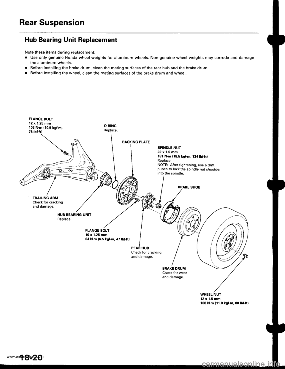
Hub Bearing Unit Replacement
Note these items during replacement:
. Use only genuine Honda wheel weights for aluminum wheels. Non-genuine wheel weights may corrode and damage
the aluminum wheels.
. Before installing the brake drum, clean the mating surfaces of the rear hub and the brake drum.
. Before installing the wheel, clean the mating surfaces of the brake drum and wheel.
FLANGE BOLI12 x 1,25 mm103 N.m 110.5 kgf.m,76 tbtfr)
BACKING PLATE
SPINDI-E NUT22 x'1.5 mm181 N.m {18.5 kgf.m, 134 lbf.ftlReplace.NOTE: Alter tightening, use a driftpunch to lock the spindle nut shoulderinto the spindle.
BRAKE SHOE
TRAILING ARMCheck {or crackingano oamage.
FLANGE BOLT10 x 1.25 mm64 N'm 16.5 kgf.m, 4? lbt.ft)
Check for crackingano oamage.
BRAKE DRUMCheck for wearano oamage,
WHEEL NUT12 x 1.5 mm108 N.m {11.0 kgt m,80lbtftl
1A-20
www.emanualpro.com
Page 920 of 1395
Rear Suspension
Hub Bearing Unit Replacement (cont'd)
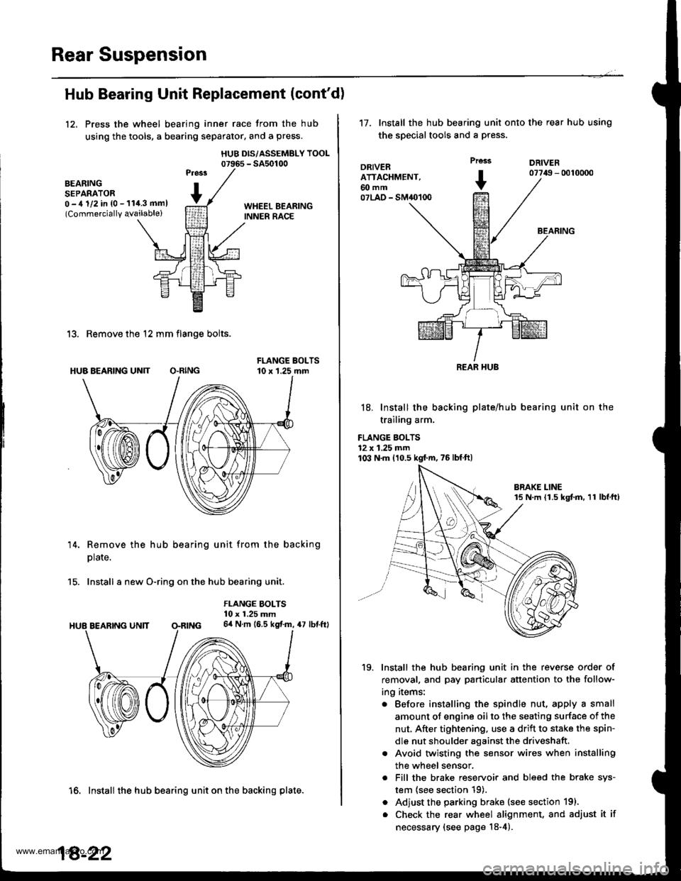
12, Press the wheel bearing inner race from the hub
using the tools, a bearing separator, and a press.
HUB DIS/ASSEMBLY TOOL07965 - SA50100
BEARINGSEPARATOR0 -,t 1/2 in {0 - 11i1.3 mml(Commercially qvailable)
13. Remove the 12 mm flange bolts.
HUB BEARING UN]T O.RING
14. Remove the hub bearing unit from the backing
plate.
15. Install a new O-ring on the hub bearing unit.
FLANGE BOLTS10 x 1.25 mm64 N.m (6.5 kgf.m, 47 lbf.ftl
16. Install the hub bearing unit on the backing plate.
18-22
't7.Install the hub bearing unit onto the rear hub using
the special tools and a press.
DRIVERATTACHMENT,60 mm07LAO - SM40100
Prcss
+
DRIVER07749 - 0010000
BEARING
18. Install the backing plate/hub
trailing arm.
FLANGE BOLTS12 x 1.25 mm103 N.m 110.5 kgf'm,75lbfft)
bearing unit on the
19. Install the hub bearing unit in the reverse order of
removal, and pay particular attention to the follow-
ing items:
. Before installing the spindle nut, apply a small
amount of engine oil to the seating surface of the
nut, After tightening, use a drift to stake the spin-
dle nut shoulder against the driveshaft.
. Avoid twisting the sensor wires when installing
the wheel sensor,
. Fill the brake reservoir and bleed the brake sys-
tem {see section 19).
. Adjust the parking brake (see section 191.
. Check the rear wheel alignment, and adjust it if
necessary (see page 18-4).
REAR HUB
www.emanualpro.com
Page 921 of 1395
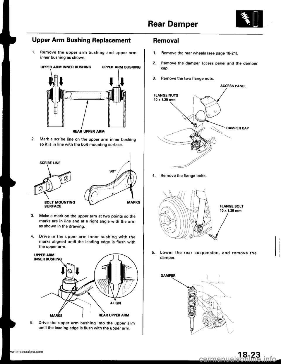
Rear Damper
1.
Upper Arm Bushing Replacement
Remove the upper arm bushing and upper arminner bushing as shown.
UPPER ARM INNER BUSHING UPPER ARM AUSHIT{G
Mark a scribe line on the upper arm inner bushing
so it is in line with the bolt mounting surface.
BOLT MOUNTII{GSURFACE
Make a mark on the upper arm at two points so the
marks are in line and at a right angle with the arm
as shown in the drawing.
Drive in the upper arm inner bushing with themarks aligned until the leading edge is flush with
the uoDer arm.
Drive the upper arm bushing into the upper armuntil the leading edge is flush with the upper arm.
REAR UPPER ARM
5.
Removal
Remove the rear wheels (see page '18-21),
Remove the damper access panel and the damper
cap.
Remove the two flange nuts.
ACCESS PANEL
OAMPER CAP
't.
4. Remove the flange bolts.
Lower the rear suspension, and remove
damper.the
1a-23
www.emanualpro.com
Page 925 of 1395
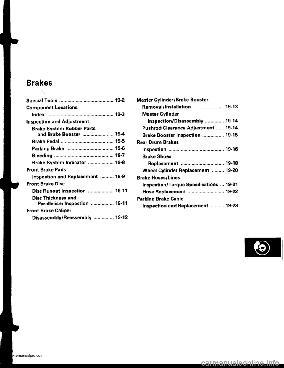
Brakes
Special Tools ............. 19-2
Component Locations
lndex ................ ...... 19-3
Inspection and Adlustment
Brake System Rubber Parts
and Brake Booster ..........,,,.......... 19-4
Brake Pedal ............ 19-5
Parking Brake ........ 19-6
Bleeding ................. 19'7
Brake System Indicator ................... 19-8
Front Brake Pads
Inspection and Replacement .......... 19-9
Front Brake Disc
Disc Runout Inspection ................... 19-11
Disc Thickness and
Parallelism Inspection ........,........ 19-1 1
Front Brake Caliper
Disassembly/Reassembly ............... 19-12
Master Cylinder/Brake Booster
Removal/lnstallation ....................... 19-13
Master Cylinder
Inspection/Disassembly .............. 19-14
Pushrod Clearance Adiustment ...... 19-14
Brake Booster Inspection ...,.,,,,....... 1 9-1 5
Rear Drum Brakes
Inspection .............. 19-15
Brake Shoes
Replacement ..... 19-r 8
Wheel Cylinder Replacement ......... 19-20
Brake Hoses/Lines
Inspection/Torque Specifications ... 19-21
Hose Replacement ....,...,............. ..,,, 19-22
Parking Brake Cable
Inspection and Replacement .......... 19-23
www.emanualpro.com
Page 927 of 1395
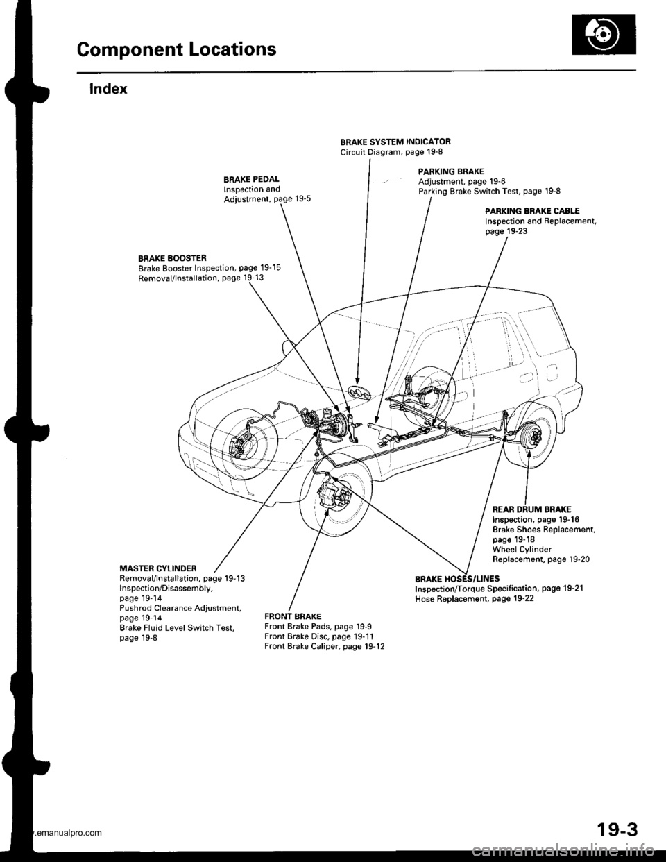
Gomponent Locations
lndex
ERAKE SYSTEM INOICATORCircuit Diagram, page't9-8
PARKING BRAKEAdjustment, page 19-6Parking Brake Switch Test, page '19-8
PARKING BRAKE CABI..EInspection and Replacement,page 19-23
BRAKE BOOSTERBrake Booster Inspection, page 19-15
Removal/lnstallation, page 19 13
MASTER CYLINDER
Inspection, pago 19-16Brake Shoes Replacement,page 19-18Wheel CylinderReplacement, page 19-20
REAR DRUM BRAKE
Removal/lnstallation, page 19-13lnspection/Disassembly.page 19-14Pushrod Clearance Adjustment,page 19 ldBrake Fluid LevelSwitch Test,page 19-8
Inspection/Torque Specification, pag€'19-21
Hose Replacement, Page 19-22
Front Brake Pads, page 19-9Front Brake Disc. page 19-11Front Brake Caliper, page 19-12
)i't ' -"''
/'"''t,'..,1 ...,. , \,,,.
i ,.'
'a.,
I
.) ..)
t ^fl)
19-3
www.emanualpro.com
Page 933 of 1395
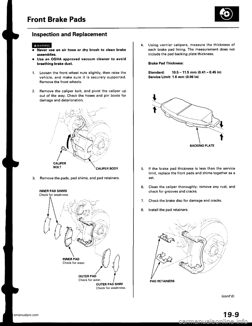
Front Brake Pads
Inspection and Replacement
1.
Nsvgr u9e an air hose or dry brush to clean brake
assemblies.
Use an OSHA approved vacuum cleaner to avoid
broathing brake dust.
Loosen the front wheel nuts slightly, then raise the
vehicle, and make sure it is securely supported.
Remove the front wheels.
Remove the caliper bolt, and pivot the caliper up
out of the way. Check the hoses and pin boots for
damage and deterioration.
CALIPERBOLTCALIPER BODY
3. Remove the pads, pad shims, and pad retainers.
INNEB PAD SHIMSCheck for weakness.
#
IOUTER PAD SHIMCheck for weakness.
i)n.
4. Using vernier calipers, measure the thickness of
each brake pad lining. The measurement does not
include the pad backing plate thickness.
Brake Pad Thickness:
Standard: 10.5 - 11.5 mm {0.,11 - 0.45 in)
Servics Limit: 1.6 mm (0.06 in)
lf the brake pad thickness is less than the service
limit. replace the front pads and shims together as a
set.
Clean the caliper thoroughly; remove any rust, and
check for grooves and cracks.
Check the brake disc for damage and cracks.
Install the pad retainers.
7.
L
(cont'd)
19-9
EACKING PLATE
'.'..i
PAD RETAINERS
www.emanualpro.com
Page 935 of 1395
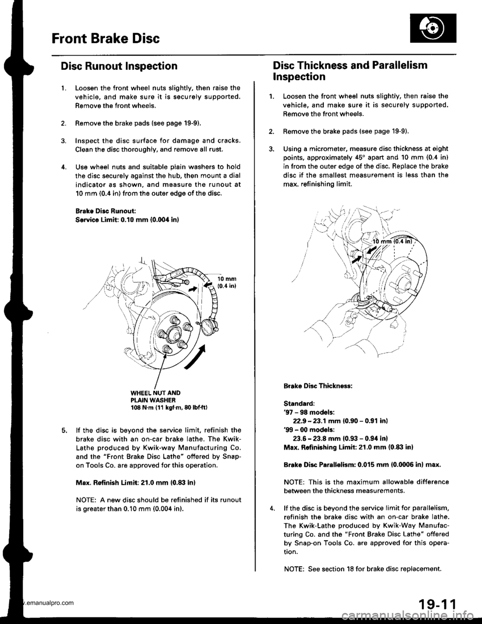
Front Brake Disc
Disc Runout Inspection
l.Loosen the front wheel nuts slightly, then raise the
vehicle, and make sure it is securely supported.
Remove the front wheels.
Remove the brake pads {see page 19-9).
Inspect the disc surface for damage and cracks.
Clean the disc thoroughly, and remove all .ust.
Use wheel nuts and suitable plain washers to hold
the disc securely against the hub, then mount a dial
indicator as shown, and maasure the runout at
10 mm (0.4 in) from the outer edge of the disc.
Brake Di3c Runout:
Service Limit: 0.10 mm {0.00,0 in)
WHEEL NUT ANDPLAIN WASHER108 N.m {11 kg{ m, 80 lbf.ft)
lf the disc is beyond the service limit, refinish the
brake disc with an on-car brake lathe. The Kwik-
Lathe produced by Kwik-way Manufacturing Co.
and the "Front Brake Disc Lathe" offered by Snap-
on Tools Co. are approved for this operation.
M8x. Rofinish Limit: 21.0 mm l0.8il in)
NOTE: A new disc should bs refinished if its runout
is greater than 0.10 mm (0.004 in).
Disc Thickness and Parallelism
Inspection
1.Loosen the front wheel nuts slightly, then raise the
vehicle, and make sure it is securely supported.
Remove the front wheels.
Remove the brake pads (see page 19-9).
Using a micromater, measure disc thickness at eight
points, approximately 45'apan and 10 mm (0.4 in)
in from the outer edge of the disc. Replace the brake
disc if the smallest measurement is less than the
max. refinishing limit.
Brake Disc Thickness:
Standard:'97 - 98 modsls:
22.9 -23.1mm {0.90 - 0.91 inl'99 - 00 mod€ls:
23.6 - 23.8 mm {0.93 - 0.94 in}
Max. Refinishing Limit:21.0 mm (o.txl in)
Brake Disc Parallelism: 0.015 mm {0.0006 in} max.
NOTE: This is the maximum allowable difference
between the thickness measurements,
lf the disc is beyond the service limit for parallelism,
refinish the brake disc with an on-car brake lathe.
The Kwik-Lathe produced by Kwik-Way Manufac-
turing Co. and the "Front Brake Disc Lathe" offered
by Snap-on Tools Co. are approved for this opera-
tron.
NOTE: See section 18 for brake disc replacement.
19-1 1
www.emanualpro.com
Page 940 of 1395
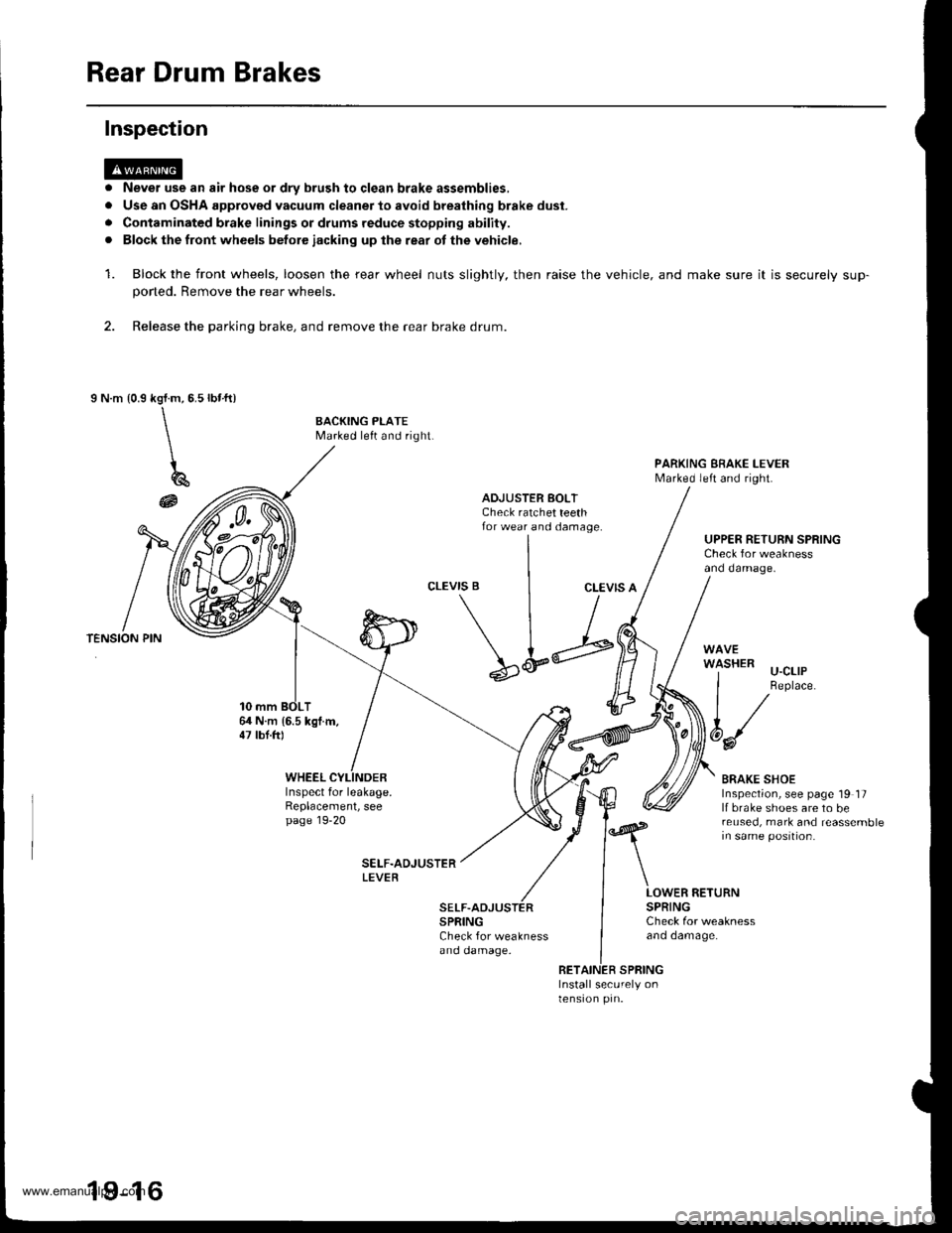
Rear Drum Brakes
Never use an air hose or dry brush to clgan brake assemblies,
Use an OSHA approved vacuum cleaner to avoid breathing brake dust.
Contaminated brake linings or drums reduce stopping ability.
Block the front wheels betore iacking up lhe rear ot the vehicle,
Block the front wheels, loosen the rear wheel nuts slightly, then raise the
poned. Remove the rear wheels.
2. Release the parking brake, and remove the rear brake drum.
I N.m {0.9rbr.ft)kgl.m,5.5
\\
\
196
@
Inspection
a
a
rl
a
1.vehicle, and make sure it is securely sup-
BACKING PLATEMarked left and right.
PARKING EBAKE I-EVERMarked left and right.
ADJUSTER BOLTCheck ratchet teethfor wear and damage.UPPER RETURN SPRINGCheck for weaknessand damage.
CLEVIS BCLEVIS A
64 N.m 16.5 kgl.m,47 lbt.ftl
\L;
SPRINGCheck for weaknessano oamage.
'l-'-' u-cllP
I Replace.
t/
6d/
BRAKE SHOEInspection, see page 19 17lf brake shoes are to bereused, mark and reassemblein same position.
WHEELInspect for leakage.Replacement, seepage 19-20
LOWER RETURNSPRINGCheck for weaknessano oamage.
RETAINER SPRINGInstall securely onlensron prn.
19-16
www.emanualpro.com